Hello! Internal heating systems mean a group of devices that supply heat. They include equipment: radiators, control devices, metering and regulation devices, shut-off and control valves, filters, etc.
These systems are divided:
— by type of coolant (air, water or steam);
- according to the wiring method (top or bottom);
- according to the method of connecting heating devices (one-pipe or two-pipe system).
With top wiring, coolant is supplied from the network from top to bottom. When, on the contrary, from bottom to top, then this is a bottom wiring.
Methods for connecting heating devices
Nowadays, the most common are single-pipe water systems with bottom vertical wiring. In this case, the radiator is connected using hoses, because they are easy to install and well guarantee uniform heating. Such a heating system requires clear calculations of the number of sections of radiators, taking into account the level of water cooling and, in addition, carefully adjusted heating devices, since water in single-pipe systems passes through them all sequentially.
The most successful heating concept, in my opinion, is the two-pipe heating system. The principle of its operation provides for the synchronous supply of hot and draining of cold water through different pipes. In addition, this concept makes it easier to calculate individual consumption.
Is an elevator needed in a heating system?
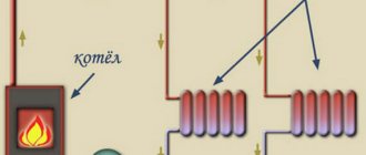
The elevator is a water-jet pump, which, due to the pressure difference, increases the pumping of coolant in the internal heating system. That is, it takes a certain amount of water from the main network, dilutes it with cooled return water from the local heating system and sends it again to heating radiators to heat apartments.
Now let's see what can happen to our heating without this necessary device. If water above 130 degrees enters the heating system, then the apartments located at the beginning of the heating system will be very hot, and the apartments located a little further away will have a consistently low temperature.
You cannot supply high-temperature water (over 130 degrees) to cast iron batteries, which can burst if there is a sudden change in temperature. For polypropylene pipes, which are now widely installed in heating systems, operating water temperatures above 95 degrees are unacceptable. For a short time, polypropylene can withstand temperatures of 100 degrees.
From all this we can conclude that the elevator unit is vital for our heating system.
It is possible to ensure optimal temperature in the apartments of multi-storey buildings in winter only by supplying hot coolant to the radiators. Heating of water to operating parameters is carried out using a special thermal unit - an elevator installed in the basement of the house or in the boiler room. We will talk about what this device is and how it functions later in the article.
Elevator unit of the heating system
The elevator circuit of the internal heating system was widespread at one time in apartment buildings due to its ability to maintain stability even with changes in pressure and temperature. The elevator does not need constant monitoring since the pressure control is carried out by the selected nozzle diameter. Modern residents of the apartment complex inherited the elevator scheme from Soviet times.
The norm for intra-house heating is a water temperature of 95 degrees, but water at a temperature of 130 to 150 degrees Celsius is supplied through the main pipelines of the heating network. Such a difference is justified by existing temperature schedules for coolant release from a heat source, but is not suitable for entering the internal pipeline.
The mechanical elevator in this scheme is designed to normalize the temperature and pressure of water before it enters the internal heating network. But besides the undoubted advantages, a mechanical heating elevator also has a number of significant disadvantages. And I wrote about this in this article.
Effect of installing washers
After installing the washers, the coolant flow through the pipelines of the heating network is reduced by 1.5-3 times. Accordingly, the number of operating pumps in the boiler room also decreases. This results in savings in fuel, electricity, and chemicals for make-up water. It becomes possible to increase the temperature of the water leaving the boiler room. For more information about setting up external heating networks and the scope of work, see.....Here you need to provide a link to the section of the site “Setting up heating networks”
Washers are necessary not only for regulating external heating networks, but also for heating systems inside buildings. The heating system risers, located further from the heating station located in the house, receive less hot water; here the apartments are cold. It is hot in apartments located close to the heating station, as more coolant flows to them. The distribution of coolant flows among the risers in accordance with the required amount of heat is also carried out by calculating the washers and their installation on the risers.
Types of heating elevators
They have a whole range of models, each selected based on the proper implementation of a specific load. These devices differ in their standard range by dimensional steps and throttle nozzles, which are calculated and adjusted for each specific option. I wrote about this in this article.
Elevator with adjustable nozzle.
Now we just have to figure out how to more easily regulate the temperature at the elevator outlet
, and is it possible to save heat using an elevator?
It is possible to save heat using a water jet elevator, for example, by lowering the room temperature at night
, or during the day when most of us are at work.
Although this issue is also controversial, we lowered the temperature, the building cooled down, therefore, in order to reheat it, the heat consumption must be increased against the norm. There is only one benefit: at a cool temperature of 18-19 degrees, we sleep better
, our body feels more comfortable.
Wednesday is assumed to last. It is complete - if it is equipped with all the elements that allow it to function as intended. It is suitable for use - if it is technically and legally legal in the form of statements, approvals and permissions for use.
The tax authorities assume that installations, systems and equipment installed in buildings can be considered complete and fit for use if. Enable all structural components to function as intended; This does not mean, however, that they are capable of self-employment.
For heat saving purposes, a special water jet elevator with an adjustable nozzle
. Structurally, its design and, most importantly, the depth of quality adjustment can be different. Typically, the mixing coefficient of a water-jet elevator with an adjustable nozzle varies in the range from 2 to 5. As practice has shown, such adjustment limits are quite sufficient for all occasions. Danfoss offers a control range of up to 1 in 1000. Why this is used in a heating system is completely unclear to us. But the price ratio in favor of a water jet elevator with an adjustable nozzle relative to Danfoss regulators is approximately 1 to 3. True, we must pay tribute to Danfos, their products are more reliable, although not all of them; some varieties of inexpensive three-way valves do not work well on our water. Recommendation – you need to save wisely!
Basic elements of the elevator
They are not permanently connected to the building, i.e. they can be switched off without damaging the building structure or installations, systems and devices. To determine whether a particular item can be considered permanent or not, you must use the classification of fixed assets.
Advantages of water jet elevators
Of course, this does not mean that every installation, system or device installed in a building can be a self-contained environment. For this to happen, the component in question. He must be classified as a permanent agent in the CST and must not be presented at the same time as the clarification in the building equipment.
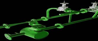
Fundamentally, all regulating elevators are designed in the same way. Their device is clearly visible in the figure.
. , you can see an animated image of the operation of the VARS control mechanism of a water-jet elevator.
And finally, a short comment - the use of water-jet elevators with an adjustable nozzle
especially
effective in public and industrial buildings
where it allows you to save up to 20-25% of heating costs by lowering the temperature in heated rooms at night and, especially, on weekends.
The opinion of the statistical office will be useful
It cannot be permanently connected to the building, i.e. it can be switched off without damaging the building, installation, system or equipment. Classification of durable means is a systematic collection of objects of durable properties. For accounting purposes, establish depreciation rates and statistical tests. The allocation of a given measure for the corresponding classification of fixed assets is determined by its purpose, design and equipment.
The authority authorized to do this is the statistical office. Therefore, the reader should contact the statistical office for assistance in classifying the asset. The statistical conclusion of the classification bureau will be important evidence before the tax authorities.
The elevator unit of the heating system is used to connect the house to an external heating network (heat supply source) if it is necessary to reduce the temperature of the coolant by mixing water from the return pipeline.
Heating system design
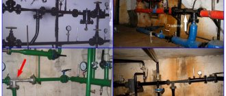
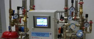
A thermal unit is a way to connect a home heating system to the main networks. The structure of the heating unit in a typical Soviet-era apartment building includes: a mud trap, shut-off valves, control devices, the elevator itself, etc.
The elevator unit is placed in a separate ITP room (individual heating point). There must certainly be shut-off valves in order to, if necessary, disconnect the intra-house system from the main heat supply. In order to avoid blockages and blockages in the system itself and in the devices of the internal house pipeline, it is necessary to isolate the dirt coming along with hot water from the main heating network; for this purpose, a mud trap is installed. The diameter of the mud trap is usually from 159 to 200 millimeters; all incoming dirt (solid particles, scale) collects and settles in it. The mud trap, in turn, needs timely and regular cleaning.
Control devices mean thermometers and pressure gauges that measure temperature and pressure in the elevator unit.
Connection diagrams
The heating unit is used in systems with various parameters, where for stable operation special connection schemes for the elevator unit are used, requiring the use of additional equipment.
Diagram of a heating unit with a water flow regulator
The water flow regulator requires manual adjustment to maintain the desired temperature
The main factor that allows regulation of the temperature of the heat flow of the heating system is water flow. Measuring this indicator causes fluctuations in the coolant in the devices and makes the operation of the heating system unstable.
To eliminate such phenomena, a regulator is installed in the system in front of the elevator unit, ensuring a constant flow of coolant.
This scheme is extremely important in houses with hot water supply, where there are periods of active water intake from the system (morning, evening, weekends, etc.).
Disadvantage: when the temperature of the leading heat flow decreases, the scheme is not effective.
Diagram of a thermal heating unit with an elevator-regulating nozzle
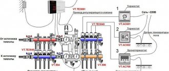
The ability to flexibly adjust the nozzle capacity allows you to maintain constant coolant output values when the temperature in the main pipeline changes.
Nozzle adjustment is effective only if the process is fully automated with the use of additional equipment:
- temperature sensor;
- pressure gauge;
- servo drive, etc.
Such schemes are not widely used due to the requirements for high pressure in the system, significantly increasing load on the nozzle and high cost.
Diagram of an elevator unit with a control pump
Scheme with a regulating circulation pump
This connection diagram is used in autonomous heating systems of private houses. It allows the unit mechanism to function normally when there is insufficient pressure in the heating network (less than 2 bar between inlet and return).
A jumper is installed between the direct heat pipe and the return pipe, on which the pump is installed; the use of a thermostat is mandatory.
Operating principle of the elevator unit
The mixing elevator serves as a device for cooling superheated water obtained from the heating network to a standard temperature before feeding it into the intra-house heating system. The principle of its reduction is to mix water at elevated temperatures from the supply pipeline and cooled water from the return pipeline.
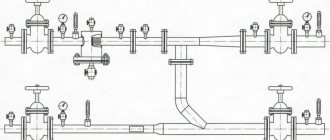
The elevator consists of several main parts. This is a suction manifold (input from the supply), a nozzle (throttle), a mixing chamber (the middle part of the elevator, where two flows are mixed and the pressure is equalized), a receiving chamber (mixture from the return), and a diffuser (exit from the elevator directly into the network with established pressure ).
The nozzle is a narrowing device located in the steel body of the elevator device. From it, hot water at high speed and with reduced pressure enters the mixing chamber, where water from the heating network and the return pipeline are mixed by suction. In other words, hot water from the main heating network enters the elevator, in which it passes through a constriction nozzle at high speed and at reduced pressure, mixes with water from the return pipeline, and then, at a lower temperature, moves into the internal pipeline. You can see what the nozzle of a mechanical elevator directly looks like in the photo below.
In modern modifications of the elevator, the technology for controlling changes in the nozzle cross-section occurs automatically using electronics. In such a system, the mixing ratio of hot and chilled water varies, which reduces the cost of the heating system. These are so-called weather-dependent or adjustable elevators, and I wrote about this in this article.
This structure of the elevator has an actuator to ensure its stable operation, consisting of a direction device and a throttle needle, which is driven by a toothed roller. The action of the throttle needle regulates the coolant flow.
Calculation and selection of elevator by number
Let’s immediately clarify the procedure: first of all, the diameter of the mixing chamber is calculated and the appropriate elevator number is selected, then the size of the working nozzle is determined. The diameter of the injection chamber (in centimeters) is calculated by the formula:
The indicator Gpr participating in the formula is the real coolant flow rate in the system of an apartment building, taking into account its hydraulic resistance. The value is calculated as follows:
- Q – amount of heat consumed to heat the building, kcal/h;
- Tcm is the temperature of the mixture at the outlet of the elevator tee;
- Т2о – water temperature in the return line;
- h is the resistance of the entire heating wiring together with radiators, expressed in meters of water column.
Reference. To insert unknown kilocalories into the formula, you need to multiply the familiar watts by a factor of 0.86. Meters of water column are converted to the more common units: 10.2 m water. Art. = 1 Bar.
An example of selecting an elevator number. We found out that the actual consumption Gpr will be 10 tons of mixed water in 1 hour. Then the diameter of the mixing chamber is 0.874 √10 = 2.76 cm. It is logical to take mixer No. 4 with a 30 mm chamber.
Now we find out the diameter of the narrow part of the nozzle (in millimeters) using the following formula:
- Dr – previously determined size of the injection chamber, cm;
- u – mixing coefficient;
- Gpr is our consumption of the finished coolant when supplied to the system.
Although the formula seems cumbersome on the surface, in reality the calculations are not too complicated. One parameter remains unknown - the injection coefficient, calculated as follows:
We have deciphered all the designations from this formula, except for parameter T1 - the temperature of hot water at the entrance to the elevator. If we assume that its value is 150 degrees, and the supply and return temperatures are 90 and 70 °C, respectively, the required size Dc will be 8.5 mm (at a flow rate of 10 t/h of water).
When the pressure value Нр at the entrance to the elevator from the central side is known, you can use an alternative formula for determining the diameter:
Comment. The result of the calculation using the last formula is expressed in centimeters.
Malfunctions of the elevator units of the heating system
Problems can occur for various reasons. This could be a breakdown of the valves or a failure of the control valve settings. If the nozzle itself is clogged, it must be removed and cleaned. If the blockage occurs in the mud trap, even before the elevator, then removal occurs by discharging the accumulated dirt using a discharge valve (dump valve) located in its lower part. If the blockage cannot be removed with this cleaning method, the mud collector must be disassembled and thoroughly cleaned.
When the diameter of the nozzle in a mechanical elevator changes directly as a result of deformation, the internal heating system becomes unbalanced. Such a problem requires immediate replacement of the nozzle itself with a new one.
Technical characteristics of standard products
The line of factory-made elevators consists of 7 standard sizes, each assigned a number. When selecting, 2 main parameters are taken into account - the diameter of the neck (mixing chamber) and the working nozzle. The latter is a removable cone, which can be changed if necessary.
See the table below for the dimensions of the component elements of the product.
The nozzle is replaced in two cases:
- When the flow area of a part increases as a result of natural wear. The reason for the development is the friction of abrasive particles contained in the coolant.
- If it is necessary to change the mixing coefficient, increase or decrease the temperature of the water supplied to the house heating system.
The numbers of standard elevators and main dimensions are given in the table (compare with the designations on the drawing).
Please note: the technical specifications do not indicate the nozzle flow area, since this diameter is calculated separately. To select the number of the finished elevator tee for a specific heating system, it is also necessary to calculate the required size of the mixing and injection chamber
Checking the condition of the elevator unit of the heating system
Such an examination has a clear sequence:
— checking the integrity of pipes;
— reconciliation of readings from control devices (pressure gauges and thermometers);
— checking pressure losses (internal resistance of the heating system);
— calculation of the mixing coefficient.
After the examination is completed, the equipment is sealed with fixed settings to avoid unauthorized interventions.
The undeniable advantage of the elevator system is its ease of operation. Since she does not need round-the-clock monitoring, it is quite sufficient to carry out routine examinations. Although, I would like to add that I myself am not a supporter of the elevator heating system scheme, and especially the scheme with a mechanical elevator. It is not modern, and was inherited from past times. Then, 30 - 50 years ago, the installation of such heating schemes was completely justified and justified. But a lot of water has passed under the bridge since then.
Selection of material for ETA-P elevator parts
When choosing a material for a particular part, take into account the nature and magnitude of the load acting on the part, the manufacturing method, requirements for wear resistance, conditions of its operation, etc.
Particular attention is paid to ensuring static and fatigue strength, since the service life of parts ranges from 10 to 25 years. For the manufacture of elevators, high-quality carbon structural steels of grades 30, 35, 40, 45, 40Х and 40ХН are used
They are used in a normalized state for the manufacture of parts experiencing relatively low stresses, and after hardening and high tempering - for the manufacture of more loaded parts. Steel grades 30 and 35 are subjected to normalization at a temperature of 880 - 900 ° C; hardening is carried out in water at a temperature of 860 - 880°C and tempering at 550 - 660°C. Parts made from steel grades 40 and 45 are subjected to normalization at a temperature of 860-880°C or quenching in water at a temperature of 840-860°C, followed by tempering; The tempering temperature is set depending on the required mechanical properties.
Installation of the elevator unit of the heating system
The place for its installation, in order to avoid problems, must meet certain parameters. You need a full-fledged room in which there will be a positive temperature, in elevator units with an automatic (weather-dependent) system; in order to avoid power outages, it is better to provide an autonomous power source.
Not so long ago I wrote and published the book “Design of ITP (heating points) of buildings.” In it, using specific examples, I examined various ITP schemes, namely an ITP scheme without an elevator, a heating unit diagram with an elevator, and finally, a heating unit diagram with a circulation pump and an adjustable valve. The book is based on my practical experience, I tried to write it as clearly and accessible as possible.
Here is the content of the book:
1. Introduction
2. ITP device, diagram without elevator
3. ITP device, elevator circuit
4. ITP device, circuit with a circulation pump and an adjustable valve.
5. Conclusion
You can view the book using the link below:
Installation of ITP (heating points) of buildings.
The heating system is one of the most important life support systems at home. Every home uses a certain heating system, but not every user knows what an elevator heating unit is and how it works, its purpose and the opportunities that are provided with its use.
Connection diagrams
The elevator unit can be used in systems with various specific features - single-pipe, autonomous or other heat supply lines. The principles of coolant supply and flow parameters do not always allow for a constant and stable output result. To organize normal heat supply to apartments or adjust the flow parameters coming from the main network, various connection schemes for elevator units are used. All of them require additional equipment, sometimes in quite large quantities, but the result achieved as a result of this compensates for the costs incurred. Let's look at the existing connection diagrams:
With water flow regulator
Water consumption is the main factor that makes it possible to adjust the heating mode of the premises. Changes in flow cause temperature fluctuations in living rooms, which is unacceptable. The issue is resolved by installing a regulator in front of the mixing unit, which ensures constant water flow and stabilizes the thermal regime.
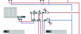
Diagram of an elevator mixing unit with a flow regulator: 1 - supply line of the heating network; 2 - return line of the heating network; 3 - elevator; 4 - flow regulator; 5 - local heating system
This solution becomes especially important in single-pipe systems, where there is a load in the form of hot water supply, which destabilizes the flow of hot water and creates significant fluctuations during active water withdrawal (morning and evening hours, holidays and weekends). At the same time, this scheme is not able to correct the situation when the temperature of the coolant in the main line changes, which is its drawback, although not too significant. A drop in coolant temperature in the supply pipelines means an accident at a thermal power plant or other heating point, and this rarely happens.
With regulating nozzle
The connection diagram of the elevator unit with the ability to adjust the nozzle capacity allows you to quickly respond to changes in coolant parameters in the main line.
Diagram of an elevator unit with a regulating needle: 1 - supply line of the heating network; 2 - return line of the heating network; 3 - elevator; 5 - local heating system; 6 - regulator with a needle pushed into the elevator nozzle
At the same time, manual adjustment is ineffective, since for this you need to constantly approach the elevator, which is usually located in the basement. The greatest efficiency of a system with an adjustable nozzle is achieved with complete automation of the process, using temperature and pressure sensors that send a signal to the elevator servo drive. This scheme allows you to gain additional opportunities when setting the operating mode, but the need for it does not always arise, but only in overloaded or unstable systems with possible fluctuations in coolant temperature.
Diagram of an elevator unit using temperature and pressure sensors that send a signal to the elevator servo drive
The disadvantages of such schemes include the need to initially ensure high pressure in the system, since adjustment is possible only within the limits of the flow parameters in the line. In addition, loads on the mechanics, in particular on the nozzle and needle, create the need for constant monitoring and timely replacement of failed elements.
With control pump
Such schemes are used in the absence of sufficient pressure in the supply pipelines for the operation of the elevator.
Diagram of an elevator unit with a correction pump: 1 - supply line of the heating network; 2 - return line of the heating network; 3 - elevator; 4 - flow regulator; 5 - local heating system; 7 — temperature controller; 8 - mixing pump
An increase in pressure makes it possible to use an elevator unit in the autonomous heating networks of a private house and allows for circulation of the coolant when the pressure in the main disappears. The pump is installed in front of the elevator or on the jumper between the forward and return pipelines before entering the elevator. To ensure normal operation, a temperature controller must be used in addition to the pump, and a power supply must be connected.
Operating principle
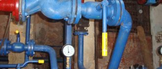
The best example that will show the operating principle of a heating elevator would be a multi-storey building. It is in the basement of a multi-story building that you can find an elevator among all the elements.
First of all, let's look at the drawing of the elevator heating unit in this case. There are two pipelines: supply (it is through it that hot water goes to the house) and return (cooled water returns to the boiler room).
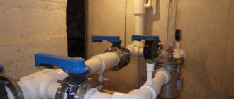
From the thermal chamber, water enters the basement of the house; there is always a shut-off valve at the entrance. Usually these are valves, but sometimes in those systems that are more thought out, steel ball valves are installed.
As the standards show, there are several thermal regimes in boiler rooms:
- 150/70 degrees;
- 130/70 degrees;
- 95(90)/70 degrees.
When the water heats up to a temperature no higher than 95 degrees, the heat will be distributed throughout the heating system using a collector. But at temperatures above normal - above 95 degrees, everything becomes much more complicated. Water at this temperature cannot be supplied, so it must be reduced. This is precisely the function of the elevator heating unit. We also note that cooling water in this way is the simplest and cheapest way.
Three way valve
If it is necessary to divide the coolant flow between two consumers, a three-way heating valve is used, which can operate in two modes:
- constant mode;
- variable hydraulic mode.
A three-way valve is installed in those places in the heating circuit where it may be necessary to divide or completely shut off the flow of water. The tap material is steel, cast iron or brass. Inside the faucet there is a shut-off device, which can be ball, cylindrical or conical. The tap resembles a tee and, depending on the connection, a three-way valve on a heating system can work as a mixer. Mixing proportions can be varied within wide limits.
The ball valve is mainly used for:
- adjusting the temperature of heated floors;
- adjusting battery temperature;
- distribution of coolant in two directions.
There are two types of three-way valves - shut-off and control valves. In principle, they are almost equivalent, but with three-way shut-off valves it is more difficult to regulate the temperature smoothly.
- How to fill water into an open and closed heating system?
- Popular floor-standing gas boiler made in Russia
- How to properly bleed air from a heating radiator?
- Expansion tank for closed heating: device and principle of operation
- Gas double-circuit wall-mounted boiler Navien: error codes for malfunctions
Recommended reading
Why do you need a heat accumulator for heating? Expansion membrane tank for a heating system: structure and functions How to make an expansion tank for heating with your own hands? What functions does a hydraulic arrow for heating perform?
2016–2017 — Leading heating portal. All rights reserved and protected by law
Copying site materials is prohibited. Any copyright infringement will result in legal liability. Contacts
Purpose and characteristics
The heating elevator cools the superheated water to the design temperature, after which the prepared water enters the heating devices located in residential premises. Cooling of water occurs at the moment when hot water from the supply pipeline is mixed with cooled water from the return pipeline in the elevator.
The heating elevator diagram clearly shows that this unit helps to increase the efficiency of the entire heating system of the building. It is assigned two functions at once - a mixer and a circulation pump. Such a unit is inexpensive and does not require electricity. But the elevator also has several disadvantages:
- The pressure difference between the direct and reverse supply pipelines should be 0.8-2 Bar.
- The output temperature cannot be adjusted.
- There must be an accurate calculation for each elevator component.
Possible problems and malfunctions
Despite the durability of the devices, sometimes the elevator heating unit malfunctions. Hot water and high pressure quickly find weak points and cause breakdowns.
This inevitably happens when individual components are assembled of poor quality, the calculation of the nozzle diameter is incorrect, and also due to the formation of blockages.
Noise
The heating elevator may create noise when operating. If this is observed, it means that cracks or scuffs have formed in the outlet part of the nozzle during operation.
The reason for the appearance of irregularities lies in the distortions of the nozzle caused by the supply of coolant under high pressure. This happens if the excess pressure is not throttled by the flow regulator.
Temperature mismatch
The quality operation of the elevator can also be questioned when the inlet and outlet temperatures differ too much from the temperature curve. Most likely, the reason for this is the oversized nozzle diameter.
Incorrect water flow
A faulty throttle will result in a change in water flow compared to the design value.
Such a violation can be easily determined by changes in temperature in the incoming and return piping systems. The problem is solved by repairing the flow regulator (throttle).
Faulty structural elements
If the connection diagram of the heating system to the external heating main has an independent form, then the cause of poor-quality operation of the elevator unit can be caused by faulty pumps, water heating units, shut-off and safety valves, all kinds of leaks in pipelines and equipment, and malfunction of regulators.
The main reasons that negatively affect the design and principle of operation of pumps include the destruction of elastic couplings in the connections of the pump and electric motor shafts, wear of ball bearings and destruction of seats for them, the formation of fistulas and cracks in the housing, aging of oil seals. Most of the listed faults can be eliminated by repair.
Unsatisfactory operation of water heaters occurs when the tightness of the pipes is broken, they are destroyed or the tube bundle sticks together. The solution to the problem is to replace the pipes.
Blockages
Blockages are one of the common causes of poor heat supply. Their formation is associated with dirt entering the system when dirt filters are faulty. Deposits of corrosion products inside pipes also increase the problem.
The level of filter clogging can be determined by the readings of pressure gauges installed before and after the filter. A significant pressure drop will confirm or refute the assumption about the degree of clogging. To clean the filters, it is enough to remove dirt through the drainage devices located in the lower part of the housing.
Any problems with pipelines and heating equipment must be corrected immediately.
Minor comments that do not affect the operation of the heating system are necessarily recorded in special documentation and are included in the plan for current or major repairs. Repairs and corrections take place in the summer before the start of the next heating season.
Malfunctions of heating elevators
The diagram of the elevator heating unit may have faults that are caused by a breakdown of the elevator itself (clogging, an increase in the diameter of the nozzle), clogging of mud traps, breakdown of fittings, or violations of the regulator settings.
The breakdown of an element such as a heating elevator device can be noticed by the way temperature differences appear before and after the elevator. If the difference is large, then the elevator is faulty; if the difference is insignificant, then it may be clogged or the nozzle diameter may be increased. In any case, diagnosis of the breakdown and its elimination should only be carried out by a specialist!
If the elevator nozzle becomes clogged, it is removed and cleaned. If the design diameter of the nozzle increases due to corrosion or arbitrary drilling, then the circuit of the elevator heating unit and the heating system as a whole will become unbalanced.
Devices installed on the lower floors will overheat, and those on the upper floors will not receive enough heat. Such a malfunction, which the operation of the heating elevator undergoes, is eliminated by replacing it with a new nozzle with the calculated diameter.
Clogging of the sump in a device such as an elevator in a heating system can be determined by the increase in the pressure difference, monitored by pressure gauges before and after the sump. Such clogging is removed by discharging dirt through the drain valves of the sludge tank, which are located in its lower part. If the blockage is not removed this way, then the mud trap is disassembled and cleaned from the inside.
In this article we are going to find out what an elevator is in a heating system and how it works. In addition to the functions, we will study the operating modes of the elevator unit and methods for its adjustment. So, let's go.
Principle of operation
Considering the diagram of a heating elevator, one cannot help but note the similarity of the finished equipment with water pumps. Moreover, for operation there is no need to obtain energy from other systems.
In appearance, the main part of the device resembles a hydraulic tee, which is installed on the return circuit of the heating system. Through a regular tee, the coolant would easily flow into the return, bypassing the batteries. This thermal unit diagram would be inappropriate.
The standard heating elevator circuit contains the following elements:
- A preliminary chamber and a coolant supply pipe with a nozzle of a certain diameter installed at the end. Water from the return circuit circulates through it.
- A diffuser is installed at the outlet, which is designed to supply coolant to users.
Today you can find units in which the size of the nozzle is adjusted by an electric drive. Due to this, you can automatically adjust the required temperature of the circulating water.
The choice of a heating unit circuit with an electric drive is made taking into account the possibility of changing the mixing coefficient of the coolant in the range of 3-6 units. This cannot be done in elevators where the nozzle cross-section does not change
Thus, units with an adjustable nozzle can significantly reduce heating costs, which is important for multi-storey buildings with central meters
Heating unit diagram
If the heating system uses a heating unit diagram for an apartment building, then its high-quality operation can be organized only on the condition that the operating pressure between the return and supply circuits is higher than the calculated hydraulic resistance.
The operation diagram of the elevator in the thermal unit is as follows:
- hot coolant is supplied through a central pipeline to the nozzle;
- circulating through small-diameter pipes, the coolant begins to increase speed;
- and a discharged zone appears;
- the resulting vacuum “sucks” water from the return circuit;
- turbulent water flows through the diffuser to the outlet.
What it is
Functions
In simple words, elevator heating units are unusual buffers between building and heating main engineering systems.
They combine a couple of functions:
- They convert the pressure difference between the lines of the highway (3-4 atmospheres) into the 0.2 required for the operation of the heating circuit.
- Help to start or hot water supply systems and stop heating.
- Allows you to switch between different operating modes of the DHW system.
Let us clarify: the temperature of the water in the taps should not be more than 90-95 degrees. In summer, when the water temperature in the highway supply does not exceed 50-55 C, the hot water supply is supplied from this thread. During the peak of cold weather, the hot water supply has to be switched to the return pipeline.
Elements
A simple diagram of an elevator heating unit includes:
- Several input valves on the supply and return lines. The supply is invariably located above the return.
- Several house valves that cut off the elevator unit from the heating system.
- Mud collectors on the supply and, less often, on the return.
- Discharge valves in the heating circuit, allowing you to completely dry it or reset the system, expelling a significant part of the air from it upon startup. It is considered good practice to dispose of waste into the sewer.
- Control valves that allow you to measure the pressure and temperature of the supply, return and mixture.
- Finally, in fact, a water-jet elevator is a flanged tee for pipes with a nozzle in.
How does an elevator heating system work? The principle of its operation is based on Bernoulli's law, which states that static pressure in a flow is inversely proportional to its speed.
How is the thermal unit arranged?
In general, the technical structure of each heating point is designed separately depending on the specific requirements of the customer. There are several basic schemes for the design of heating points. Let's look at them one by one.
Thermal unit based on an elevator
The scheme of a heating point based on an elevator unit is the simplest and cheapest. Its main drawback is the inability to regulate the temperature of the coolant in the pipes. This causes inconvenience for the end user and a large overconsumption of thermal energy in the event of thaws during the heating season. Let's look at the figure below and understand how this circuit works:
In addition to what is indicated above, the thermal unit may include a pressure reducer. It is installed on the feed in front of the elevator. The elevator is the main part of this scheme, in which the cooled coolant from the “return” is mixed with the hot coolant from the “supply”. The operating principle of the elevator is based on creating a vacuum at its output. As a result of this vacuum, the coolant pressure in the elevator is less than the coolant pressure in the “return” and mixing occurs.
Thermal unit based on a heat exchanger.
A heating point connected through a special heat exchanger allows you to separate the coolant from the heating main from the coolant inside the house. The separation of coolants allows for its preparation using special additives and filtration. With this scheme, there are ample opportunities to regulate the pressure and temperature of the coolant inside the house. This allows you to reduce heating costs. To have a clear idea of this design, look at the figure below.
The mixing of coolant in such systems is done using thermostatic valves. In such heating systems, in principle, aluminum radiators can be used, but they will last for a long time only if the coolant is of good quality. If the PH of the coolant goes beyond those approved by the manufacturer, then the service life of aluminum radiators may be greatly reduced. You cannot control the quality of the coolant, so it is better to play it safe and install bimetallic or cast iron radiators.
DHW can be connected in a similar way via a heat exchanger. This offers the same benefits in terms of hot water temperature and pressure control. It is worth saying that unscrupulous management companies can deceive consumers by lowering the hot water temperature by a couple of degrees. For the consumer, this is almost unnoticeable, but on a household scale it allows you to save tens of thousands of rubles per month.
Territories of responsibility
What is an elevator heating unit - we have at least figured it out.
And who is responsible for it?
- The section of the highway into houses up to the flanges of the inlet valves is the territory of responsibility of the heat transporting organization (heating networks).
- Everything after the entrance valves, and the valves themselves, are the responsibility of the housing organization.
But: selection of a heating elevator by number (standard size), calculation of retaining washers and nozzle diameter are carried out by heating networks. Housing workers only provide dismantling and installation.
Flaws
- The outlet temperature is not always adjustable. For example, at a low temperature of the coolant in the heating main, after mixing with cooled water (return), water will initially flow into the internal circuit pipes, the temperature of which is not sufficient to heat the room. This problem is currently being solved by installing adjustable units. Adjustment can be carried out manually (by rotating the valve) or automatically (adjustment occurs due to the movement of the rod installed inside the nozzle, the movement occurs due to the connection of a servo drive connected to sensors);
- For stable operation of a system with an elevator unit, precise selection of design is necessary;
- Some users consider one of the disadvantages to be the material investments required to purchase additional equipment and install elevator heating units. But with proper installation of high-quality equipment, even a system with automatic control of nozzle capacity pays for itself within 3-5 years (due to savings on heating fees).
Control
The controlling organization is, again, heating networks.
What exactly do they control?
- A couple of times during the winter, control measurements of pressures and temperatures of the supply, return and mixture are carried out . In case of deviations from the temperature curve, the calculation of the heating elevator is carried out again with boring or reducing the diameter of the nozzle. Obviously, this should not be done during the peak of cold weather: at -40 outside, the access heating system can become covered in ice within an hour after the circulation stops.
- In preparation for the heating season, the condition of the shut-off valves is checked . The check is extremely simple: all valves in the assembly are closed, after which any control valve opens. If water comes from it, it is necessary to look for a malfunction; In addition, in any position of the valves, they should not have leaks through the seals.
- Finally, at the end of the heating season, the elevators in the heating system, along with the system itself, are tested for temperature . When the DHW supply is turned off, the coolant heats up to high values.
Features of the operation of central heating stations, installation of heating points
The heating system is fed by the return pipeline of the heating network. Heat sources and thermal energy transport systems The heat source for TPs are heat generating enterprises, boiler houses, and combined heat and power plants.
Water from the external water supply network is supplied to the DHW heater.
Compensation for the decrease in pressure level is carried out through a group of pumps. Viewed: The DHW circuit can be designated as single-stage, independent and parallel.
Correction mode is automatic. Often, heat from the domestic hot water system is used by consumers for partial heating of premises, for example bathrooms in multi-apartment residential buildings. The flow of hot mains water to the 2nd stage heater is controlled by the temperature controller (thermal relay valve) depending on the water temperature behind the 2nd stage heater.
The schematic diagram of an individual heating point is approved.
Certificate for flushing and pressure testing of heating networks, heating systems and hot water supply systems.
All this equipment must operate exclusively in automatic mode, so it is critically important to correctly set up the entire set of equipment for work in a particular home
Central heating stations should be located on the boundaries of microdistricts between the main, distribution networks and quarterly ones. One of them is the heating system. If there is a central heating point in each individual building, it is necessary to install an ITP, which performs only those functions that are not provided for in the central heating point and are necessary for the heat consumption system of a given building.
This device can be represented as a container. But the cost of such a device is much higher, although its use is more economical. Heat consumption is controlled and taken into account. After the elevator, the return line will also be counted.
After the elevator unit, the mixed coolant is supplied to the heating system of the building. The installation company must be a member of the SRO. Further, as the most common, we consider a TP with a closed hot water supply system and an independent connection circuit for the heating system. Creating a schematic diagram of an individual heating point in AutoCAD P&ID
Control
We present the order of execution of some operations related to the operation of the elevator.
Start heating
If the system is full, you just need to open the house valves and circulation will begin.
There are a couple more complicated instructions for starting the reset system.
- The discharge on the return pipeline opens and the discharge on the supply closes.
- Slowly (to avoid water hammer) the upper house valve opens.
- Once clean, air-free water has been released into the discharge, it closes, after which the lower house valve opens.
Useful: if modern ball valves are installed on the risers, the direction of operation of the discharge circuit does not matter. But in screw valves, a rapid countercurrent can tear off the valves, after which the mechanic will have to spend a long and painful search for the circumstances of the stoppage of circulation in the risers.
Work without nozzle
When the return temperature is catastrophically low during the peak of cold weather, it is practiced to operate the elevator without a nozzle. The system receives coolant from the highway, not the mixture. The suction is suppressed with a metal pancake.
Differential adjustment
If the return flow is too high and it is not possible to replace the nozzle in a timely manner, adjusting the differential with a valve is practiced.
How to do it yourself?
- The supply pressure is measured, after which the pressure gauge is placed on the return line.
- The inlet valve on the return line closes completely and slowly opens, with pressure controlled by a pressure gauge. If the valve is installed, its cheeks may not completely move down the stem and will slide down later. The price of the wrong procedure is guaranteed defrosted access heating.
At a time, aim to remove no more than 0.2 atmospheres of difference. Repeated measurement of the return temperature is carried out every other day, at a time when all values have stabilized.
Possible problems
As a rule, most problems in the elevator unit arise for the following reasons:
- clogging in equipment;
- changes in the diameter of the nozzle as a result of equipment operation - an increase in the cross-section makes it more difficult to regulate the temperature;
- blockages in mud traps;
- failure of shut-off valves;
- regulator failures.
In most cases, finding out the cause of problems is quite simple, since they are immediately reflected in the temperature of the water in the circuit. If the temperature differences and deviations from the standards are insignificant, there is probably a gap or the nozzle cross-section has increased slightly.
A difference in temperature readings of more than 5 ℃ indicates the presence of a problem that can only be solved by specialists after diagnostics.
If, as a result of oxidation from constant contact with water or involuntary drilling, the cross-section of the nozzle increases, the balance of the entire system is disrupted. Such a flaw must be corrected as quickly as possible.
It is worth noting that in order to save money and use heating more efficiently, electricity meters can be installed at heating units. And hot water and heat meters make it possible to further reduce utility bills.
Types of heating elevators
Oddly enough, not even all plumbers servicing multi-story buildings know about heating elevators. At best, they have an idea that this device is installed in the system. But how it works and what function it performs is not known to everyone, not to mention ordinary people.
Therefore, let's eliminate this gap in knowledge about heating systems and examine this device in more detail.
Master Class. An example of installing a heating radiator with your own hands
Let's consider the algorithm of actions when connecting a battery to a heating system.
Step 1. First, prepare and assemble the heating radiator itself. Clean all threaded holes from factory grease, for which you can use a special cleaning agent and a brush.
Radiator preparation
Step 2. When finished, remove any remaining cleaning product with a paper towel.
It is important that the holes are as clean and dry as possible.
The hole is wiped dry
Step 3. Install adapters (in our example these are ½ and ¾ inches).
Adapter
Step 4. Install the “American” faucet onto the adapter that you installed in advance. To tighten, use a special key for “American women”. As a result, you will equip a pair of holes - inlet and outlet (in the example they are located diagonally).
The “American” is installed. The key for “American” is used. The key for “American” is used.
Step 5. Install plugs on any unnecessary holes that need to be closed.
Installing the plug
Step 6. Prepare the shanks (these are special thin tubes) and cut them. Remove the internal chamfer in the shanks
Then feel the internal parts - it is important that you do not feel any burrs there
The tube (shank) is being prepared. A device for removing the internal chamfer
Step 7. Place the nut, brass spacer and rubber band on the tube (in that order). Then expand the tube using a special device, inserting it inside until it stops. After expansion, the tube will no longer be able to jump out of its place under the influence of pressure during operation of the heating system.
Pipe expansion
Step 8. Move the elastic and other parts to the extended edge, attach the adapter.
Step 9. Mark the place where the radiator will be installed on the wall, in accordance with the requirements described above. To begin, determine the center of the window sill, measure down 10 cm - the battery mounts will be located exactly at this level.
Marking
Step 10. Draw a line for installing the holders parallel to the window sill at a distance of 10 cm. The holders themselves will be attached to dowels.
Drawing a line for installing holders
Step 11. Another fastener will be located 12 cm from the floor surface along the vertical center line.
Installing the Bottom Mount
Step 12. Place the battery on the mounts and level it.
Heating radiator installation
Step 13. Mark on the wall the places where the grooves will be located (in our example, the pipes will be laid inside the wall). Do this in all places where pipes will be connected to the radiator.
Marking for future wall grooves
Step 14. Perform grooves on the previously planned areas. Remove the battery to make it easier to carry out work.
Grooving
Step 15: Prepare the tubes. Make a mark where they will be cut, as shown in the picture below.
Preparing pipes for connecting the radiator
Step 16. Connect the battery and faucet to the soft line laid in the wall. Tighten all connections tightly. The input should be located at the top, and the output, accordingly, at the bottom.
Pipe connection
Video - How to install a heating radiator
If you choose a suitable scheme and familiarize yourself with all the nuances of the connection, then installing the radiator yourself will be quick and without any problems. You just need to act carefully and do everything efficiently. The quality of heating your home depends on how correctly you do everything!
Calculation
The operation of the elevator unit depends on the correctly selected dimensions and pressure difference between the discharge and return pipelines. To calculate the parameters of the elevator unit, heating engineers and programmers have created quite a lot of programs. They look like a regular screen form with a customized formula for calculations. After filling out all the rows of the table, the program calculates the parameters of the hot water supply scheme, the dimensions of the elevator and displays the results in the form of a diagram with plotted dimensions and in the form of a table with calculations. The option for displaying results is usually presented in the form of a table.
The calculation of the heating network and the choice of elevator is described in some detail in the Building Codes and Rules:
- SNiP 23-01-99 “Building climatology”, 2000;
- SNiP II-3-79 “Construction Heat Engineering”, 1998;
- SNiP 2.04.05-91 “Heating, ventilation and air conditioning”, 1987;
- Bogoslovsky V.N. “Internal sanitary installations”, 1990.
The mixing thermostat is an alternative to the standard elevator unit. It works in exactly the same way as an elevator - it mixes the hot water coming from the thermal power plant and the cooled water that returns from the radiators. Three channels are connected to the thermostat: one for hot water, the second for return, and the third for supplying the prepared mixture to the heating radiators. If the temperature of the water from the main pipeline is within acceptable limits, the cold flow is completely blocked. As soon as the temperature begins to rise, the valve gradually begins to open, a portion of cool water is added to the hot water, lowering the temperature of the mixture. The hotter the water, the larger the volume of cool water is added. A three-way mixing thermostat valve is necessary to control the proportion of cold and hot water in order to obtain the coolant at the optimal temperature. Advantages: small dimensions, no moving parts, easy temperature adjustment.