Warm water floors are gaining popularity today; they are a sign of comfort. But for such heating to function effectively, a pumping and mixing unit is required. It allows you to achieve the optimal temperature level of the coolant, as well as regulate its flow into the loops.
Therefore, we decided to talk about existing models of pumping and mixing units and their configuration. You will learn how to assemble a mixing unit for heated floors with your own hands, as well as how to install and configure it.
Pumping and mixing unit
Functions
The use of a thermo-mixing unit when installing a heated floor allows you to build an independent water heating system with the ability to adjust the temperature of the coolant.
Hydrofloor heating is a low-temperature equipment. Water should be supplied to the floor pipeline at a temperature of no more than +55 degrees. Since this structure is often connected to a battery or boiler, where the degree of heating of the liquid is much higher, a special mixing module is required.
It is in this unit that the cooled coolant from the return flow is mixed with hot water coming from the heating source to the required level.
This water mixing device also controls the volume of coolant flowing into each loop.
Recommendations
When choosing the optimal type of underfloor heating system, you must first take into account the thermal conductivity of the material under which the device will be placed and the branching pipes with other components.
The best option is parquet; in fact, all types of wood are excellent heat conductors. By placing the system under such a floor covering, it will be possible to achieve good heating of the floor surface.
The second important factor is the system itself; it is recommended to choose only products from trusted brands, with the possibility of contacting a repair service during the warranty period.
This will allow you to avoid additional, unexpected expenses if something breaks or malfunctions in the system. The warranty period allows you to fix the problem at the expense of the manufacturer; the work process also includes dismantling and subsequent installation of the floor covering, in fact the entire range of work.
Principle of operation
The essence of the functioning of any model of pumping and mixing device is the same. The flow of heated coolant, moving from the source, passes through a thermostat, where its temperature is recorded. Then the water enters the fuse, where its temperature level is regulated by opening and closing the head.
If the degree of heating of the coolant exceeds the specified value, then the fuse opens the damper and cooled water is added from the return line. When the desired degree is reached, the supply is blocked.
The pump is responsible for the circulation of fluid in the hydraulic system; the uniform heating of the floor surface depends on its operation.
Areas of use
The need for a pumping and mixing unit arises if the coolant is water. Let's find out in what cases this happens.
- If the water heated floor is connected from central heating - since the heating of water in the centralized system exceeds the required level for underfloor heating.
- When connected from a boiler that does not operate with a return flow of +55 and below - these are all solid fuel boilers and those operating on gas.
- If the main line consists of two or more circuits with different temperatures (warm floors with radiators).
Basic rules for installing a warm water floor circuit
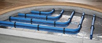
A water-heated floor heats the surface of the finishing coating indirectly through a concrete screed, the thickness of which is 5 cm. If installed correctly, under this screed there are the following elements:
- water and steam protection made of polyethylene film;
- rough concrete screed 15 cm thick;
- heat-insulating layer made of foil insulation.
In addition, another layer of steam and water protection is laid on top of the heating screed.
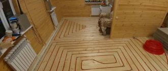
The water heated floor register is laid out at a distance of 50 cm between the knees and no closer than 20 cm to the walls. One end of the pipe is removed from the boiler through the mixing unit, the second is the return line and is connected to it in front of the boiler.
Water heated floor register layout
The screed device involves the use of pipes without joints, which is only possible when using plastic or metal-plastic pipes. The joint is the weak point of the pipeline, and if repairs are necessary, the screed will have to be dismantled.
Kinds
All pumping and mixing units are divided according to the type of working body:
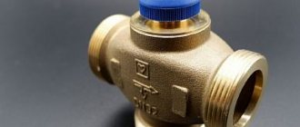
- With a three-way valve - installed in rooms with a large area, since the device is capable of passing a large volume of water. Such a tee for mixing is often connected to an external temperature sensor, which makes it possible to set the heating level based on the outside temperature. The adjustment process is carried out using a valve, which is located at the junction of the supply and return pipes. The design scheme generally used is sequential.
Three-way valve
- With two-way - recommended for rooms up to 200 m2, connected via both parallel and series mixing circuits. The valve has a thermal head with a sensor, it controls the temperature level, and if the indicator is exceeded, the hot water supply is shut off. The volume of liquid that this design is capable of passing through is small, so the adjustment process is smooth.
Two way valve
- Combined - combines a valve and a balancing unit. But this option is rarely used with heated floors.
Selecting a thermostat
I would also like to touch upon the thermostat itself, which plays a very important key role in this heating system. There are the following types of temperature controllers for heated floors:
Electromechanical. The clarity of such adjustment is approximate, so achieving a specific set temperature is quite problematic.
The main advantage of such a device is its low price.
Electronic. Setting the desired value is done using touch buttons and has fairly clear settings and the ability to set the temperature limit down to one degree.
Programmable electronic. By installing such an element, you can not only regulate the temperature in the room, but also turn on the heating according to a schedule, or only when there is a person in the room.
By the way, some thermostats already have a built-in sensor, which makes it possible to control not only the temperature of the floor, but also the air in the room as a whole.
As a result, I would like to remind you about the rules for working with electrical equipment; all connection work is carried out with the power turned off.
At the same time, it is necessary to ensure that no one, except the person performing this work, accidentally supplies voltage dangerous to human health and life. This is where our technology for installing a heated floor temperature sensor with your own hands ends. We hope the information provided was useful to you!
DIY collector
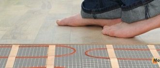
Warm floors have long been a sign of high-standard rooms.
Their use is due to the high quality of heating - the room is heated throughout the entire volume due to natural convection, since the entire floor area serves as a heater for the air in the room.
The floor itself is heated by an electric, film or good old water heater - a hot water boiler.
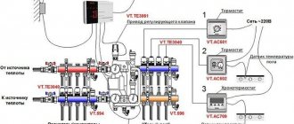
Schemes of pumping and mixing units
Pumping and mixing units are assembled in several ways, the difference lies in the connection of the pump and in the form of a valve.
Node connection diagrams
Pump-mixing unit for heated floors.
With series pump connection
When the pump is turned on, only the coolant is prepared according to a sequential scheme and ensures its movement through the loops. Despite the need for two separate devices for pumping liquid through the primary and secondary circuits, this scheme is more technologically advanced.
It has increased performance than parallel connection. Therefore, professionals often use this option when installing heated floors.
However, for the efficiency of the floor during such an assembly, the correct calculation and settings, as well as the accuracy of the drawn drawing, play an important role.
With parallel
The advantage of a parallel circuit is that only one device is required to pump water through both circuits. This greatly simplifies the assembly process, but a more powerful unit is required.
If the mixing device is planned for a small heating system, then a parallel arrangement is recommended. Since when assembling such a structure with your own hands, fewer problems occur, it is therefore easier to avoid serious errors. But for large areas of heated floors, this scheme is not suitable - low productivity and efficiency.
Is it worth making a collector yourself - conclusions
If you want to connect 3-4 floor circuits on a budget basis, then it’s definitely worth the hassle with polypropylene. Provided that the comb is planned to be placed in the boiler room, and not inside a beautiful cabinet somewhere in the corridor. Soldering must be done very carefully so that after 1-2 years your product does not leak.
When it is necessary to assemble a manifold for 8-10 underfloor heating circuits, use fittings made of high-quality brass. Of course, in terms of dimensions, such a product will be larger than the factory one, but it will allow you to save on the number of parts.
Which mixer is better to choose?
It is necessary to select a thermal mixer taking into account the characteristics of the heating device. When choosing distribution equipment, you need to take into account the method of mixing - central or lateral.
If the area is large, with several separate circuits, then it is necessary to install a mixing unit with a three-way valve. This unit can handle large volumes of liquid perfectly. For a single-circuit floor, a manifold with a two-way mixer is suitable.
You can make a pumping and mixing unit for heated floors with your own hands, but if you buy a ready-made one, we recommend these models:
- VT.COMBI and VT.COMBI.S - for the preparation of low-temperature coolant, a two-way valve is used, it is controlled by a thermal head or servo drive. The temperature sensor is not included in the package - must be purchased separately.
- VT.COMBI - the unit is equipped with a balancing valve, with the help of which the pressure in the system is adjusted.
- VT.COMBI.S - for this NSU model, the collector can be connected both at the input and at the output. Therefore, it is used for two types of heating (radiator and TP).
- VT.DUAL - the mechanism includes two modules (pumping and thermostatic), with a manifold group located between them. Mixing is carried out by a three-way valve with a thermal head.
NSU VT.COMBI.S
These are proven models and it is better to buy them.
Homemade designs
The collector has a significant drawback - high cost.
Therefore, many “homemade” people assemble various options for collectors with their own hands, depending on their wallet and the availability of components.
There are two options for this path:
The 3-loop collector circuit can be implemented as follows:
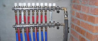
First, you should assemble the collector pipes - return and coolant supplying the heating circuits. To do this, use one comb for 3 channels or 3 single-loop units for each collector.
The return manifold is equipped with a flow sensor or flow meter and a counter-mounted connection unit for return supply hoses along each loop.
Single-loop manifolds are connected by threaded elements into a comb. Each coolant loop contains a heat sensor with an actuator and a connection point for the heating circuit power line.
Air vents are connected to one end of the collectors, and on the other, a coolant pump is connected to the collector pipes, and in addition a thermostatic valve or servo drive is connected to this point, which replenishes the mixer with hot water from time to time.
The assembled collector is attached to the wall, tested for functionality and connected to the thermal circuits. After this, final installation and configuration of the entire system is carried out.
Here is the simplest working version of a manifold for heated floors, available to a wide range of DIYers. The capabilities of real collectors are often expanded by connecting more complex control and metering systems.
For example, they connect heat meters, additional temperature meters and much more, no matter what - that’s why homemade inventors exist, to “assemble something yourself.”
If a homemade manifold is soldered from polypropylene pipes, then you need to replenish your arsenal of tools with a special soldering iron for welding parts made of this polymer.
When assembled by welding, the size of each single-loop unit increases due to the seams, and if there are more than 3 thermal circuits, then the entire collector becomes bulky and its installation becomes problematic. Otherwise, the design of the plastic manifold and its settings are no different from those described earlier.
Well, now it's time to finish the article. All the material I wanted to share has been reviewed. I hope it will be useful to you, and you will use it if you need to install a mixer for heated floors with your own hands. Improve your own practical skills and gain new knowledge, as they say: “It’s never too late to learn!” That's all, thank you for your attention, successful and easy repair!
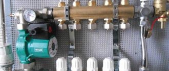
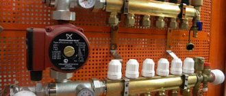
Equipment
The mixing unit is a complex mechanism, responsible for maintaining a stable water temperature and for its continuous circulation. It is included in the collector block and consists of a number of mechanisms.
Pump
The main function of the pump is to create a constant movement of water through the pipeline. It supplies and returns it through the collector and floor branches. Its main indicators are pressure and productivity.
If calculated correctly, the pump will ensure that the hydraulic resistance in the floor line is overcome. It is recommended to use a device with an automatic operating mode switch.
Circulation pump
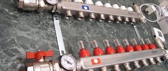
Flow regulator
Flow meters are:
- Primary circuit balancing valve (float) - it is responsible for the amount of coolant that enters the main line from the primary high-temperature source. The flow is regulated due to its throughput. The adjustment is made by a valve with a head; it is rotated with a key. Adjustment is also carried out by the thermostat valve, which is controlled by a remote sensor.
- Balancing valve of the secondary circuit - it is adjusted depending on the size of the heated area. By opening and closing the control valve, the proportions of the heated and cooled flow change. Closing the balancing valve of the secondary circuit return leads to an increase in the supply of hot coolant from the boiler, and this leads to an increase in thermal conductivity.
The degree of opening is adjusted using a scale printed on the flask. It determines the throughput of the device in m3 per hour.
Balancing valve
Bypass valve
The bypass, together with the bypass valve, helps ensure uninterrupted operation of the pumping equipment when the backpressure mode is in effect - when the circulation of liquid through the floor pipeline is completely or partially stopped. This can happen if the loop valves on the comb are closed manually or using taps.
As a result, the resistance to water flow increases, as well as the load on the mechanism. The pressure level in the system increases and the bypass valve opens.
The coolant flows through the bypass pipes and the pump, thereby closing a small circulation cycle. This leads to the elimination of emergency situations.
Bypass
Auxiliary elements
Auxiliary elements are also responsible for the functions of monitoring and maintaining the efficient operation of the pumping and mixing structure. This:
- thermometer - controls the temperature of the coolant;
- air vent - air is removed from the system through it;
Air vent
- drainage taps, their purpose is to drain water;
- check ball valve - prevents the flow of coolant in the opposite direction.
Collector block
Collector group - heated floor circuits are connected to it, calculated for a certain number of branches. It includes feed and return combs.
Is the VALTEC COMBIMIX pump and mixing unit worth it?
Making a mixing unit with your own hands
When constructing warm water floors, you can choose a ready-made model of a pumping and mixing unit. But if you want to make a budget knot with your own hands, then we will tell you in detail the step-by-step process.
Before you start work, you need to stock up on: a strainer, a three-way thermostatic and check valve, two thermometers, a circulation pump, an air vent, two tees, two drain and ball valves. And also, manifolds - for the supply pipeline with ball valves and for the return pipeline with regulators.
In addition, the number of loops of a warm water floor should be equal to the outlets on the collector.
Step-by-step assembly instructions:
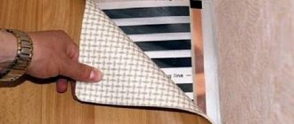
- We mount a mesh filter to the ball supply valve, after which we install a corner.
Screw the filter to the feed
- We screw a three-way thermostatic mixing valve to the corner.
Installing a three-way valve
- We screw a check valve to the mixer, to the side where the return line will be connected - without it, the unit will not work correctly.
Connecting the check valve
- We install thermometers to the return and to the middle outlet of the mixing unit.
We fix the thermometers
- We connect a circulation pump to the thermometer coming from the supply pipe. It is necessary that the straight distance from the thermometer to the pump, and from the pump to the collector, be equal and equal to 10 diameters of the supply pipe.
Installing the pump
- Next, we mount the collectors, which are fixed on a special bracket. We connect the supply manifold with ball valves to the pump, the return manifold will have control valves.
We install the collector group
- We screw tees to the end outlet of the supply and return manifold, to which the air vent is attached.
Connecting the tees
- We install an air vent.
- We install a drain ball valve at the side outlets of both tees. They are necessary to fill or drain the system.
- We connect a piece of polypropylene or metal-plastic pipe to the return manifold. Its size should be equal to the distance from the supply manifold to the thermometer.
We attach a piece of pipe to the return line
- We place a second mesh filter between this section of pipe and the return thermometer.
Installing a second filter
- We screw the ball valve to the check valve.
Connecting the return valve
The result was a simple, cheap model of a homemade pumping and mixing unit for heated floors.
Ready node
Pumping and mixing unit for heated floors: a budget option
Cost of materials
- union nuts - RUB 257/piece;
- nipples – 110 RUR/piece;
- air vent (manual) – 101 rubles;
- thermostats - from 2000 rubles;
- check valve - from 200 rubles;
- circular pump – from 2400 rubles;
- tees; various types of connections, etc. – from 100 rub.
Thus, the approximate cost of parts for assembling a floor heating system with your own hands will be about 6-9 thousand rubles.
If you compare the cost of self-installation and purchasing everything ready-made with calling specialists, then the mixing unit alone will cost at least 15 thousand rubles. If we take into account all other expenses, the amount will be quite large - from 30 thousand rubles. and higher.
Whether you assemble the system yourself or not is up to you. Of course, not everyone can cope with this task. Experience with plumbing and dexterous hands are required. However, for a person who has decided to save a couple of tens of thousands of rubles, there are no unsolvable problems!
Installation of the mixing unit
Before installing the distribution unit, it is necessary to determine its location. It can be installed in the room where the floor will be installed, or in the boiler room of a private house.
It is possible to mount the unit directly on the wall or in a metal cabinet, which is mounted into a recess made in the wall. It is equipped with adjustable guides and doors. A collector placed in such a cabinet looks aesthetically pleasing, but it is not cheap. It is important that all electrical appliances are grounded. And also access to the device was free.
The mixer should be mounted at the top point of the system, this will simplify the release of air from it.
The pumping and mixing unit is installed in the following sequence:
- A niche is prepared in which the manifold cabinet is placed.
Making a niche for the closet
Installing a cabinet
- The mixing and distribution unit is installed in the cabinet.
We fasten the pumping and mixing unit
- The corresponding pipes from the boiler are connected to the manifold ball valves.
Connect the collector to the supply
- The floor contour pipelines are screwed to the outlets of the comb.
Connecting the floor pipeline
The heated hydraulic floor structure has been installed, you can check its quality for leaks. Only after this, the screed is poured and the finishing material is laid.