The traditional heating system in the form of radiators was the only source of heat for a long time, but today it is being replaced by heated floors. They are electric and water. The key to efficient operation of water heating is the presence of a collector and its correct installation.
This article will be useful to those who are planning to install heated floors in their home and install the collector themselves. In it we will talk about the existing types of this equipment, their structure and installation method.
Why do you need a collector?
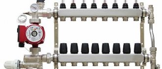
Essentially, a collector is a pipe with holes for the inlet and outlet of the coolant; it is also called a distribution and mixing unit. The function of the device is to maintain the required temperature level in the system and control the water flow.
The device is designed to mix water coming from the boiler, where it is heated, with cooled liquid coming from the return line to the required level for heated floors. After all, in a boiler the coolant usually warms up to +90 degrees, and for a heated floor this is a high temperature.
It requires +40 - 45 degrees, so you can’t do without a collector. If water flows directly from the heat source into the circuits, this will lead to overheating of the system and its failure.
In addition, the circuits have different lengths, and their need for thermal energy is different. Therefore, a special unit is needed between the boiler and the pipeline, which will distribute the flow of hot water through the loops.
Types and principle of operation
Collector devices differ in the material from which they are made - brass, plastic or stainless steel. And also by type of valve:
- With two-pass - the design feature is continuous heating of the coolant. Heated water is supplied continuously, and shut-off valves regulate its volume. As a result, the surface is heated evenly, while overheating of the system is not possible. But this model is not suitable for rooms whose area is more than 200 m2.
- With three-way - universal equipment, recommended for large rooms. According to the technology, installation with a servo drive is allowed (we suggest you learn more about servos in more detail) and various automation. The valve is capable of creating optimal operating pressure, adjusting the temperature level and the amount of coolant supplied.
Kinds
In addition, there are 4 types of collectors:
- Simple - a tube with shut-off valves, having internal and external threads. The model is cheap, but there is no function for setting up the system. To install such a collector on heated floors, additional elements are required.
- Equipped with valve outlets for adjustment, and valves for connecting circuits - a Chinese device. It is not uncommon for a structure to leak, but repairs are not difficult, just change the gasket. The distance between the supply and return pipes does not coincide with European standards, so various devices are required.
- With control valves and Eurocones - an expensive model. It does not have ball valves, but there are fittings and adjustment valves; a servo drive can be installed on them, which will regulate the temperature in the line.
- With flow meters - they are located on the supply pipe of the manifold, and on the return pipe there are sockets for servos. This device is intended for heated floors with circuits of different lengths; the presence of flow meters allows you to regulate the volume of coolant in each circuit.
Any model is equipped with outlets for draining water and air.
Principle of operation
The general principle of operation of the unit, regardless of the type of valve (two or three-way), is to distribute the flow of water along the loops of the heating floor, which circulates under the influence of the pump. The amount of coolant entering each branch is controlled mechanically or automatically by a servo drive.
The work process looks like this:
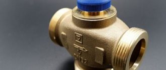
- Coolant heated to 60 - 80 degrees is supplied from the source to the comb through a thermostatic valve;
- A flow of chilled water from the return flow comes from the distributor;
- The shut-off valve has a head that regulates the temperature of the fluid;
- The mixed two streams are fed into the mixing pump, then the water is distributed through the pipelines.
When the heating temperature of the coolant in the main decreases to the required level, heated water from the source is mixed in, a two or three-way valve is responsible for this.
Seven most popular models
| Illustrations | Recommendations |
| Model No. 1: LUXOR. The Italian brand LUXOR produces reliable brass equipment.
| |
| Model No. 2: GIACOMINI. Another bright representative of Italian quality.
| |
| Model No. 3: ARS. These Turkish-Italian manifolds are of excellent quality at a reasonable price; such equipment can be called the golden mean.
| |
| Model No. 4: FADO. The company itself is Italian, but now they have begun cooperation with APC and the products can be declared as joint production.
| |
| Model No. 5: BIANCHI. The technical characteristics of the Italian collector BIANCHI are similar to its Italian counterpart from GIACOMINI. The only difference is the number of circuits and price. Here the combs come from 2 to 10 pins, and the price ranges from 9–22 thousand rubles. | |
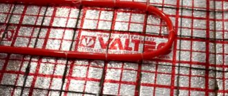
| Model No. 6: Valtec. The Italian brand Valtec is one of the most popular on our market.
| |
| Model No. 7: Caleffi . The Italian manufacturer Caleffi operates in the luxury goods sector. The combs are made of brass, steel and polymer; the characteristics here are among the highest, but the price also reaches 43 thousand rubles. |
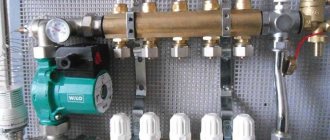
Manifold cabinet design
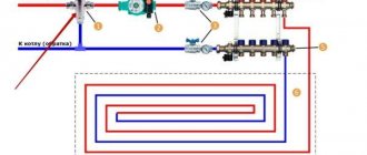
A manifold cabinet is a structure that includes a pumping and mixing unit and a manifold block.
Manifold for underfloor heating and heating. Review, assembly and installation of the STOUT manifold block
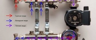
Pumping and mixing unit
This unit is designed to dilute heated water going into the water floor line with waste, cooled coolant. The pump impellers are responsible for the mixing process.
It is the pump that supplies the liquid diluted to the required degree into the system. Moving through the pipes, it gives off heat to the room and when cooled, returns to the mixing unit.
The temperature regime is adjusted using balancing valves; with their help, the flow of waste water in the pipes is also regulated. To heat a small room, the shut-off valve must be opened; if the room is small, it must be closed.
This manifold circuit for underfloor heating is equipped with a thermal head, which is responsible for the temperature level in the system. It opens or closes the heated water supply plug. When the flow of coolant stops, the bypass valve opens and the liquid moves through the free bypass.
With a simple method of tying the collector, manual temperature adjustment is done. To automate the process, a servo drive with a thermostat is used. The servo drive receives a signal from the thermostat about the temperature level in the room, and based on this indicator, it opens or closes the return manifold damper, thereby regulating the circulation of water in the floor.
Main indicators characterizing the pumping and mixing unit:
- operating pressure - maximum value 10 bar;
- temperature level - +90 degrees (maximum);
- temperature range - from 20 to 60 degrees.
Collector block
The manifold cabinet is equipped with a unit responsible for regulating the water flow, which enters the floor line and returns.
Technical indicators:
- product diameter - 1 or 1.25 inches;
- number of bends - from 3 to 12;
- pressure (working value) - 10 bar;
- The maximum heating level of the coolant is +100 degrees.
The collector block has two rows of bypasses . One, the so-called direct row, is responsible for adjusting the volume of hot coolant, the other (reverse) regulates the cooled water.
Correct assembly of the manifold for heated floors
Assembling a purchased factory-made manifold is a simple process. Included:
- a distributor with rotameters, it is connected to the supply - it has 2 or more outlets for circuits;
- return comb with thermal valves instead of flow meters;
- automatic air vents;
- taps with plugs for supplying and draining water from the heated floor main;
- inlet and outlet temperature thermometers;
- shut-off ball valves and brackets.
When purchasing a device, its complete set can be changed based on the budget and the method of connection to the boiler. It is acceptable to install a distributor without rotameters or 1 thermometer, not 2.
Build process
Assembly instructions for underfloor heating manifold
The factory device is made so that anyone can install it with their own hands. That is, more often the distribution parts are sold already assembled; only the heated floor circuits need to be connected to them, and parts that have an auxiliary value must be connected.
The equipment should be assembled in stages:
- The device is removed from the packaging. In factory models, the supply and return pipes already have flow meters and valves. If the knot is divided into several parts, then they should be twisted together.
- The collector is fixed on a bracket, this will allow further assembly with greater convenience.
- The remaining parts are attached - an air vent, valves, plugs and control devices.
- Ball valves are mounted on the return manifold.
The circulation pump and valves should be attached after fixing the device to the wall.
Installation process
In order to carry out installation, you must first prepare all the components. For example, VALTEC manifold systems are supplied disassembled. To get started you need:
- Use a screwdriver to remove one of the brackets for securing the device.
- Install shut-off valves.
- Screw automatic air vents onto them.
- Next are the drain valves.
- Afterwards the plugs are installed and the mounting bracket is returned to its place.
Instructions for installing the collector yourself are not particularly difficult:
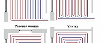
- To begin with, choose a location so that the length of all heating circuits is approximately the same.
- Next, you should fix the device on the wall so that the manifold cabinet assembly for a heated floor with a liquid pump can easily fit in it, and all adjustments can be made quickly and conveniently. Usually this is a box no larger than 1x1 m in size and 12 cm thick.
- After fastening, all pipes are connected and the cabinet is assembled.
Tips and tricks
Before buying a collector, make calculations of the required length of pipes and their position. It would be better to install two 6 flow meters instead of one for 12, which will help equalize the pressure and temperature in areas that are too distant. The installation diagram of the collector must provide for its location at a level higher than the warm floor or heating circuit so that air is removed from the pipes correctly and automatically.
https://youtube.com/watch?v=JuPDaHfrBL0
| Manufacturer | Cost depending on the number of flow meters, rubles | ||||
| 2 | 3 | 4 | 5 | 6 | |
| Oventrop | 4 100 | 5 150 | 6 100 | 7 000 | 8 100 |
| Watts | 3 550 | 4 650 | 5 700 | 6 750 | 7 800 |
| Kermi | 3 500 | 4 400 | 5 500 | 6 450 | 7 500 |
| Rehau | 8 200 | 9 350 | 10 700 | 12 150 | 13 550 |
| Valtec | — | 6 600 | 7 950 | 9 300 | 10 700 |
| Manufacturer | Price | |||||
| 7 | 8 | 9 | 10 | 11 | 12 | |
| Oventrop | 9 250 | 10 200 | 11 300 | 12 250 | 13 400 | 14 400 |
| Watts | 9 000 | 9 950 | 11 000 | 12 050 | 13 100 | 14 250 |
| Kermi | 8 550 | 9 600 | 10 700 | 11 750 | 12 700 | 13 850 |
| Rehau | 15 250 | 16 900 | 18 350 | 19 800 | 21 450 | 22 550 |
| Valtec | 12 400 | 13 850 | 15 250 | 17 200 | 18 050 | 19 450 |
Based on the data given in the table, we can conclude: the cost of the Kermi collector for a heated floor system today is one of the most affordable, despite the fact that it is a high-quality product from a German company, made of stainless steel.
The expensive price category is represented by the young Russian-Italian company Valtec and the German “dinosaur” Rehau. The first, which appeared in 2002, has already managed to enrich its range with brass and steel appliances and manifold cabinets. The second, having the same assortment, has more than 60 years of experience. That is why Rehau collectors for underfloor heating systems with flow meters occupy the highest price category in the table, because by trusting professionals, the chances of failure are minimal.
Installation of a heated floor collector
Installation of the collector and connection of underfloor heating circuits
Having assembled the main elements, you can proceed to the installation and connection of the heated floor collector. The process consists of several steps:
- Location and installation location. The standard height for mounting the collector on the wall from the base of the floor is 500 - 1000 mm; it should not be installed lower, since it will be difficult to connect floor pipes to it. In addition, it should be placed so that the length of all loops is the same, and there should be free access to it, preferably in the middle of the room.
- Installation of the manifold cabinet. A manifold cabinet is installed at the planned site, usually its size is 1 by 1 m, with a wall thickness of 12 cm. It can be placed in an equipped niche or mounted directly on the wall. The surface of the wall must be flat, otherwise the structure may malfunction.
- Fastening the comb in the box. The cabinet is equipped with special guides, they can be moved to the required distance, it depends on the length of the collector. They have fasteners - bolts, with the help of which the device is fixed in the box.
- Installation of the pump and valves (two or three way) is carried out according to the planned diagram. On the supply pipe that comes from the boiler, a valve with a thermal head is first mounted, then the pump is installed on flanges with union nuts; it should be placed between the valve and the manifold. You cannot install the pump in front of the shut-off valve, otherwise the valve will not function and the water will not flow correctly.
Connecting the TP to the collector
The heated floor circuits must be connected to the comb outlets using a threaded connection under the Eurocone. More often, the Eurocone has a diameter of 17 mm, while the floor hose is 16 mm. Therefore, it will need to be calibrated to this size. Then:
- it is necessary to put a union nut on the tube, insert a ferrule ring and a thrust sleeve;
- manually connect the end of the hose to the comb fitting;
- finally tighten with two keys - one fixes the hexagon on the fitting, the other tightens the connection.
Manifold setup
Manifold for heated floors. Three ways to configure flow meters.
The process of setting up a manifold for water heated floors is done according to the following instructions:
- removing the cap from the shut-off valve;
- securing the valve with a hexagon;
- determining the number of revolutions for a specific loop;
- turning the valve the calculated number of times.
The remaining underfloor heating circuits can be adjusted in the same way.
The service life and quality of the floor depend on how accurately the adjustment is made.
How to make a comb from polypropylene
A distributor welded from polypropylene fittings is the cheapest manifold for a warm water floor that you can think of. It has several disadvantages:
- the design is large in size and will not fit into every box, so it will have to be mounted on the wall in the boiler room;
- It is quite problematic to install flow meters, so there simply won’t be any;
- you need to be good at soldering polypropylene so as not to make a mistake at any of the many joints.
Conclusion. It makes sense to make a PPR comb when it is planned to be installed in a boiler room, and the number of outlets is designed for 3-5 circuits, otherwise the design will be too cumbersome. The dimensions can be judged from the photo, which shows a manifold with only 2 connections, the third outlet is for connecting the main line from the boiler.
To work, you will need no more than 2 m of PPR pipes with a diameter of 32 mm and the same tees according to the number of bends. In addition, polypropylene-metal threaded adapters, ball valves and straight radiator valves used for balancing are needed. Make a manifold for heating circuits of underfloor heating according to the instructions:
- Having carefully measured the depth of the pipe entering the tee and placing a mark on the outside, solder these 2 parts together.
- Set aside the same distance from the edge of the fitting along the pipe and cut it off and clean the end. Solder the adapter coupling to the lower branch of the tee.
- Repeat the operations outlined in paragraphs 1 and 2. Weld the resulting second block with the first, then move on to the third, and so on.
- Solder an elbow or tee at one end of the PPR for mounting an air vent, and at the other end - a coupling for a ball valve.
Examples of PPR collectors - for 3 and 9 branches
Advice. Weld the fittings close to each other, otherwise the structure will grow to unimaginable sizes and will look unsightly.
When the main welding work is done, all that remains is to screw the taps and radiator valves to the couplings, and put the automatic air vent in place. Details of the assembly of the unit are clearly demonstrated in the video:
Is it possible to install the collector below the level of the heated floor - for example, in the basement?
There are cases when the distribution and mixing unit has to be installed not on the floor where the heated floor is laid, but below, for example, if the boiler room is in the basement, or you simply do not want to spoil the interior of the apartment.
This wiring is acceptable; the collector is installed in the same sequence as usual. There is only one problem - automatic bleeding of air masses from the line is not possible if the air vent is located on the comb.
The solution is to install an air vent on the return pipe between the comb and the floor hinges, and a shut-off device with a shut-off valve is installed in front of it. It is necessary to have access to an air vent.
For your information! Since an air vent is required for each branch of the floor, it is worth considering the advisability of installing the collector below the level of the heated floor.
A warm water floor is a modern heating system that is perfect for installing in private homes. With proper installation of the floor “pie” and the collector, the design can provide comfortable conditions in the room.