Warm water floors are gaining popularity today; they are a sign of comfort. But for such heating to function effectively, a pumping and mixing unit is required. It allows you to achieve the optimal temperature level of the coolant, as well as regulate its flow into the loops.
Therefore, we decided to talk about existing models of pumping and mixing units and their configuration. You will learn how to assemble a mixing unit for heated floors with your own hands, as well as how to install and configure it.
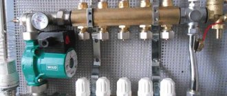
Pumping and mixing unit
Connection via three-way valve
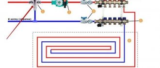
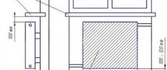
A slightly different assembly and operating principle is the option of connecting a heated floor through a three-way valve, which is shown with an arrow in the diagram below.
This scheme is used in cases where, in addition to a heated floor, the system also contains a main heating circuit. The temperatures of the coolant in them will be different, which is why a mixing valve is needed.
Connection via three-way valve
- This device not only regulates the water supply to the circuit (it is mounted on the supply pipe in front of the circulation pump), but also at the same time, using a built-in thermostat, controls its temperature, mixing cold coolant with hot one. In this case, the pressure in the pipeline corresponds to the pressure set on the pump.
- However, the valve cannot accurately dose the amount of water for mixing, so the temperature in the floor circuit may be either underheated or too hot. The problem is solved by connecting a servo drive to it, since it is this that balances the operation of the system and protects the floors from overheating.
Three-way mixing valve
The circuit with a mixing valve is quite accessible for self-installation, and the equipment for it does not require large expenses.
Errors and problems
To save money, many simplify the design, excluding important elements. But this should not be done for the following reasons:
- With closed radiators and a functioning heated floor, the boiler and heat pump pumps will interfere with each other’s operation.
- When radiators and floor heating are operating, the floor pump can reduce the pressure, thereby reducing the circulation of water in the radiators.
- Even when the boiler equipment is stopped, the TP pump moves liquid through the boiler and radiators, which is impractical. And if unnecessary movement of the coolant in the batteries can be dealt with by installing a check valve, then it will not be possible to stop the movement of water flows in the boiler.
- The absence of a protective thermostat can cause failure of the mixing unit, excessively hot water will enter the floor pipes, and there is a risk of damage to the screed.
- In the absence of a bypass valve, if the floor loops are closed, the circulation of liquid in them stops. Moreover, if you forget to turn off the pump, then it works on a closed valve and heats up, which leads to rapid failure.
You may not need to install a bypass valve if:
- one floor contour will be constantly open;
- the pump has frequency regulation;
- TP automation can control the circulation and, if necessary, turn off the equipment.
If you decide to heat a private house using a combined heating system - warm floors and radiators, you should familiarize yourself with all the diagrams, their pros and cons. Only then, you need to move on to choosing a model in accordance with your requirements, financial capabilities and characteristics of the room.
Diagram with two-way valve
Install it on the supply from the heating device. A balancing adjustable valve is installed in the place of the jumper between the supply pipeline and the return line. It is adjusted in accordance with the required temperature of the supplied water, usually using a hex key. It is needed to regulate the amount of cold coolant.
The temperature sensor is placed after the pump, which in turn moves water in the direction of the comb. Only now the intensity of movement of the heated coolant from the boiler changes. In this way, the temperature of the supply water changes at the pump inlet, while the cold flow is adjusted and stable.
Mixing always occurs and water from the boiler does not enter directly into the circuits, since this is impossible. This scheme can be considered more reliable. But it should be noted that a mixing group equipped with a two-way element is capable of heating 150 - 200 “squares” of area, since there are no valves with greater capacity.
Equipment
The mixing unit is a complex mechanism, responsible for maintaining a stable water temperature and for its continuous circulation. It is included in the collector block and consists of a number of mechanisms.
Pump
The main function of the pump is to create a constant movement of water through the pipeline. It supplies and returns it through the collector and floor branches. Its main indicators are pressure and productivity.
If calculated correctly, the pump will ensure that the hydraulic resistance in the floor line is overcome. It is recommended to use a device with an automatic operating mode switch.
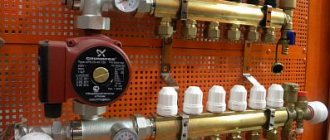
Circulation pump
Flow regulator
Flow meters are:
- Primary circuit balancing valve (float) - it is responsible for the amount of coolant that enters the main line from the primary high-temperature source. The flow is regulated due to its throughput. The adjustment is made by a valve with a head; it is rotated with a key. Adjustment is also carried out by the thermostat valve, which is controlled by a remote sensor.
- Balancing valve of the secondary circuit - it is adjusted depending on the size of the heated area. By opening and closing the control valve, the proportions of the heated and cooled flow change. Closing the balancing valve of the secondary circuit return leads to an increase in the supply of hot coolant from the boiler, and this leads to an increase in thermal conductivity.
The degree of opening is adjusted using a scale printed on the flask. It determines the throughput of the device in m3 per hour.
Balancing valve
Bypass valve
The bypass, together with the bypass valve, helps ensure uninterrupted operation of the pumping equipment when the backpressure mode is in effect - when the circulation of liquid through the floor pipeline is completely or partially stopped. This can happen if the loop valves on the comb are closed manually or using taps.
As a result, the resistance to water flow increases, as well as the load on the mechanism. The pressure level in the system increases and the bypass valve opens.
The coolant flows through the bypass pipes and the pump, thereby closing a small circulation cycle. This leads to the elimination of emergency situations.
Bypass
Auxiliary elements
Auxiliary elements are also responsible for the functions of monitoring and maintaining the efficient operation of the pumping and mixing structure. This:
- thermometer - controls the temperature of the coolant;
- air vent - air is removed from the system through it;
Air vent
- drainage taps, their purpose is to drain water;
- check ball valve - prevents the flow of coolant in the opposite direction.
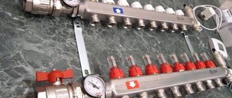
Collector block
Collector group - heated floor circuits are connected to it, calculated for a certain number of branches. It includes feed and return combs.
Is the VALTEC COMBIMIX pump and mixing unit worth it?
Manifold for underfloor heating system
For heated floors, a common collector unit is most often installed, or a separate collector is installed in front of each heating circuit. If the latter option is implemented, then all collectors are equipped with flow meters, thermostats, as well as the following elements:
- Return and supply mixing valve;
- Shut-off valve for balancing the heating device;
- Overflow valve.
You can assemble a collector for a heated floor yourself using different schemes, and in some schemes of collector units bypasses are used, but not always - only in single-circuit systems. If the underfloor heating system is organized according to a dual-circuit scheme, then the collector can be connected without a bypass to the secondary circuit.
Double-circuit underfloor heating system with collector
Before assembling a manifold assembly for a heated floor, weigh your options - sometimes it’s easier to buy a ready-made structure. If you are going to buy a collector, it is better that all its parts and elements are from the same manufacturer. When assembling the unit yourself, you must select the material from which the main components of the unit will be assembled: copper, steel, polymers or brass.
Also, when choosing an industrial design, it is important to consider the following parameters:
- How many heating circuits will there be in the system (usually from 2 to 12), the total length of the pipeline and the capacity of the circuits;
- Maximum permissible pressure in pipes;
- Possibility of expanding the heating system;
- Manual or automatic collector control;
- Electrical power of all components and assemblies;
- The diameter of the internal holes of the collector (throughput).
Do-it-yourself collector
The most efficient operation of the assembled collector units can be ensured by connecting heating circuits of equal length to them. In order to equalize the length of the pipelines with sufficient accuracy, they are divided into equal sections, which are connected to the collector. The easiest way is to calculate the collector unit in a special computer program or on an online calculator, so that the phenomenon called “thermal zebra” does not appear, that is, uneven heating of the floor.
For the calculation you will need the following data:
- Type of decorative flooring;
- the area of the heated room and the plan for placing large objects in it;
- Material and diameter of circuit pipes;
- Boiler rated power;
- Type of floor insulation.
Reservoir calculation
Collector installation - recommendations
When designing a heated floor system, you first need to find the optimal location for installing the collector. Typically, the unit is installed in a manifold cabinet, and the cabinet itself is mounted at a height of 30-40 cm from the floor level next to the supply and return.
In order not to blame your own mistakes and ensure maximum heating of the heated floor pipes, study the instructions for connecting the collector. Then assemble the unit in the following sequence (this applies to an industrial manifold unit):
- Unpack the tubes for forward and reverse coolant supply. The tubes must have flow meters and supply valves. If the collector is multi-sectional, assemble the sections into one structure;
- From the assembled sections you need to assemble a unit on brackets (included in the kit);
- Next, we install shut-off valves, automation, sensors and other connecting fittings;
- We attach the unit to the wall or in a cabinet, install a thermostat, a servo drive and a circulation pump;
- We connect the pipes from the boiler and the pipes from the heating circuits of the “warm floor” system.
Manifold set
Now the connection diagram for the heated floor collector is pressed, after which the concrete screed can be poured. Thermal adjustments of the collector can be carried out after installation of the finishing coating.
DIY collector unit
A factory manifold is a fairly expensive product, so many craftsmen want to make it themselves. You will still have to buy many elements, but the cost will be cheaper. The easiest way is to solder a homemade manifold from PVC pipes and fittings Ø 25-32 mm. You will also need tees and bends of the same diameters, and shut-off valves.
Homemade collector
The number of valves and fittings is calculated by the number of heating circuits. The tools you need are a soldering iron for propylene elements and attachments for it, special scissors for cutting pipes and a tape measure.
Marking the collector consists of marking and cutting pipes of the required length, observing the minimum distance between the tees. Valves and transitions are soldered to the PVC tees with a soldering iron. Fittings for connecting the pump are soldered to this structure. As you can see, everything is simple, but it is better to buy more complex collector units ready-made.
Making a mixing unit with your own hands
When constructing warm water floors, you can choose a ready-made model of a pumping and mixing unit. But if you want to make a budget knot with your own hands, then we will tell you in detail the step-by-step process.
Before you start work, you need to stock up on: a strainer, a three-way thermostatic and check valve, two thermometers, a circulation pump, an air vent, two tees, two drain and ball valves. And also, manifolds - for the supply pipeline with ball valves and for the return pipeline with regulators.
In addition, the number of loops of a warm water floor should be equal to the outlets on the collector.
Step-by-step assembly instructions:
- We mount a mesh filter to the ball supply valve, after which we install a corner.
Screw the filter to the feed
- We screw a three-way thermostatic mixing valve to the corner.
Installing a three-way valve
- We screw a check valve to the mixer, to the side where the return line will be connected - without it, the unit will not work correctly.
Connecting the check valve
- We install thermometers to the return and to the middle outlet of the mixing unit.
We fix the thermometers
- We connect a circulation pump to the thermometer coming from the supply pipe. It is necessary that the straight distance from the thermometer to the pump, and from the pump to the collector, be equal and equal to 10 diameters of the supply pipe.
Installing the pump
- Next, we mount the collectors, which are fixed on a special bracket. We connect the supply manifold with ball valves to the pump, the return manifold will have control valves.
We install the collector group
- We screw tees to the end outlet of the supply and return manifold, to which the air vent is attached.
Connecting the tees
- We install an air vent.
- We install a drain ball valve at the side outlets of both tees. They are necessary to fill or drain the system.
- We connect a piece of polypropylene or metal-plastic pipe to the return manifold. Its size should be equal to the distance from the supply manifold to the thermometer.
We attach a piece of pipe to the return line
- We place a second mesh filter between this section of pipe and the return thermometer.
Installing a second filter
- We screw the ball valve to the check valve.
Connecting the return valve
The result was a simple, cheap model of a homemade pumping and mixing unit for heated floors.
Ready node
Pumping and mixing unit for heated floors: a budget option
Controlling the operation of a heated floor system
The efficiency of heating devices depends not only on their power and adjustments, but, above all, on the condition of the heated object. If a building is not insulated enough, no system will create conditions for comfortable living in it. Walls made of porous materials such as sawn shell rock or foam concrete reduce heat loss by 20 - 25% compared to ceramic bricks; additional wall insulation and wind protection, as well as insulation of the roofing pie, give approximately the same effect.
Turning to the issue of controlling the operating mode of heated floors, it should be noted that two main approaches are used: manual control of the mixing unit and the use of automatic control systems.
The first option is used for small buildings consisting of 2 or 3 living rooms and auxiliary premises. Setting the mixing mode is done manually using an ordinary tap.
For complex, developed heating networks, this method is unrealistic due to the multifactor nature of the process and complex automated devices are used.
Heating control systems can be:
- group - their task is to convert the water temperature at the outlet of the boiler of 75 - 90 degrees into the 35 - 40 degrees required for low-temperature circuits at the inlet and control the temperature of the return flow, making adjustments to the mixing mode. Naturally, changes in weather conditions also affect the amount of heat transfer in the heating system;
- individual - the coolant flow rate for each circuit is set so that the room has a constant temperature within a given range. This is achieved either by installing a temperature sensor in the room or by monitoring the return flow temperature at the outlet of the register directly at the collector unit.
Equipment
It is impossible to display the entire variety of devices in a short article, so we will focus on some of their typical representatives:
Group controllers
Heating is controlled by applying a pulse to the servo drive of the control valve, which performs the corresponding manipulation. Up to 10 channels from sensors are installed in one controller to adjust the mixture in various circuits. Programming is possible.
Heated floor operating mode control unit
When an external temperature sensor is connected, the coolant heating temperature mode changes preventively.
Thermostats
A remote device capable of measuring temperature at the installation site and transmitting data about it to the heating system control unit. The device can transmit information both over wires and over a radio channel. It should be installed in a place protected from sunlight and away from drafts.
Room thermostat for water floor
A device for directly controlling the temperature of the coolant flow. Placed in a pipeline rupture. Usually equipped with a servomotor to control the damper. It is calculated at work at a system pressure of up to 16 atmospheres.
Three-way thermostatic valve in a heated floor control system
Servo
A device that actuates a valve's shut-off device (stem). The small-sized device creates a force of more than 10 kg.
Servomotor for underfloor heating valve
Design and purpose of a temperature sensor
So, the temperature sensor for a heated floor system is a thermistor protected by a glass bulb, and also has a copper conductor about 3 meters long for connection to the thermostat.
In addition to the glass bulb for tile floors, the temperature sensor itself is also protected by a gel shell. The conductor is insulated with high-quality PVC (polyvinyl chloride) to protect it from external influences and damage. The length of the conductor can be increased, and naturally, reduced, up to 50 meters, the main thing is that there is an undamaged sensor at the end of the conductor.
To easily replace it in the future, it is recommended to place this structure in a metal-plastic tube, even if the manufacturer included a plastic corrugation with a diameter of 16 mm.
The metal-plastic pipe has a smoother inner surface, so it is much easier to remove and install, as well as connect a new temperature sensor in case of failure. These types of temperature sensors are installed in hard floor coverings (under tiles or porcelain stoneware).
Another type of sensors recommended for laminate, carpet, that is, soft types of flooring material, are special plastic cylinders that are connected to the end of the electrical cable.
The principle of operation of the temperature sensor is very simple; when the temperature changes, its resistance changes, thereby giving a signal to the thermostat to turn on or off the heated floor system from 220 V, the most common network in everyday life.
Direct connection diagram
You have a boiler, after which all safety fittings + a circulation pump are installed. In some wall-mounted boiler versions, the pump is initially built into its body.
For floor-standing units you will have to install it separately. From this boiler, the water is first directed to the distribution manifold, and then disperses through the loops. After which, having completed the passage, it returns through the return line to the heat generator.
With this scheme, the boiler is directly adjusted to the desired temperature of the TPs themselves. You don't have any additional radiators or radiators here.
What are the main features worth paying attention to here? Firstly, with such a direct connection, it is advisable to install a condensing boiler. In such schemes, operation at relatively low temperatures for the condenser is quite optimal
In this mode it will achieve its highest efficiency
In such schemes, operation at relatively low temperatures is quite optimal for the condenser. In this mode it will achieve its highest efficiency.
If you use a regular gas boiler, you will soon say goodbye to your heat exchanger.
The second nuance concerns solid fuel boilers. When you have it installed, for direct connection to heated floors, you will also need a buffer tank.
It is needed to limit the temperature. It is very difficult to directly regulate the temperature with solid fuel boilers.
What does a single lever kitchen faucet consist of?
Single-lever models are more stylish, modern and easy to use.
The advantages of such models are:
- Easy to use. You can adjust the temperature and water pressure with one hand.
- Economical. The design of the device allows you to quickly adjust the temperature and intensity of the jet. This allows you to significantly reduce water consumption.
Single lever models consist of elements:
- aerator;
- housings;
- a switch made in the form of a lever;
- "spout";
- cartridge.
To adjust the water temperature, the lever is rotated horizontally. The intensity of the pressure is adjusted by moving the lever in the vertical plane.
The aerator, which is installed on most models, makes use more convenient - the device prevents splashing and reduces noise levels. In addition, the device helps reduce water consumption.
The main element of the single-lever version is the cartridge. It can be of two types:
- Ball. It is based on a hollow sphere in which three small holes are located. Cold and hot water flows through two of them. Third - to output water at the required temperature. The structure is connected directly to the handle, which changes the position of the sphere.
- Disk. Its principle is similar to the operation of a crane axle box. The device consists of two disks made of metal ceramics. One of the planes is movable and moves together with a lever. Each disk has a hole. When they coincide, water enters the system. If not, the flow is blocked.
Models with ceramic cartridges are the most common.
How to properly assemble and connect the collector
Install the frame - the collector is mounted in a horizontal position directly on the wall, or in a cut-out niche. The only condition for installation is free access to the heating pipe arrow. It is also possible to install a manifold cabinet yourself
The cabinet will allow you to hide the wiring from prying eyes, which is especially important if a bathroom or hallway is used as a boiler room.
Connection to the boiler - coolant supply is from below, return is from above. Ball cut-offs must be installed in front of the frame.
A pump group is installed immediately behind the taps. To maintain the required temperature, the heated coolant is only partially used. The pump not only creates the necessary pressure in the heating system, but also helps to mix cooled water from the floor circuit and heated water coming from the boiler. A bypass valve with a temperature limiter is installed. A distribution comb is installed behind the valve. The distribution of the collector to heated floors is carried out as follows. The pipes going to the heated floor are attached from above, from the heating system from below. If you need to assemble a distribution manifold for a warm water floor with your own hands, shut-off valves with a built-in thermostat are installed in the comb. Practice shows that the best option is to purchase a ready-made structure. Assembling a manifold, even by a professional, and adjusting the valves independently is a labor-intensive process that requires certain skills and experience. Connecting a warm water floor collector requires the use of special components. Compression fittings are used, consisting of a support sleeve, a clamping ring and an intermediate brass nut. After installation, the collector is configured.
Pressure testing of the collector - after completing the installation work, it is necessary to check the sealing of the connections. To do this, the completed collector group is connected to a pump (pressure tester). Using a pressure tester, pressurize the system. The water circuit is left under pressure for a day. If the pressure readings have not changed, it means that the installation of the heated floor manifold with your own hands was done correctly and the mixing unit is ready for operation.
At first glance, installing the collector yourself seems quite simple. But as practice shows, it is better not to start installation without the necessary tools and special skills.
Features of installing a water floor in a high-rise building
It is believed that the construction of a water floor system in high-rise buildings is impossible, but this is not entirely true. In practice, such a project can be implemented, but requires agreement with the central heating service provider. They can be installed exclusively on the first floors of buildings.
How to make a water floor in a multi-story building?
Two options are used here: completely replacing the radiator system with a water floor or installing an additional heating system along with the operation of radiators.
The optimal location for connecting a water heated floor system in an apartment building is the place where the return of the common riser is connected to the main line that discharges the coolant to the boiler room
In the first case, it is necessary to carefully calculate the coolant flow in the new system, since it must correspond to the previous volumes. It is not necessary to reconstruct all the heating in the apartment; you can limit yourself to just one room.
If the water floor plays the role of auxiliary heating, heat meters will be needed. In addition, it is necessary to clarify whether a centralized heating system can cover the increased power and coolant consumption.
If a high-rise building has a radiator system with overhead wiring, then it is best to connect the water floor at the junction of the return of the common riser with the main line leading to the boiler room. Filters must be installed in front of the water floor.
This is necessary, given the low quality of the coolant in domestic centralized systems, otherwise the heated floor circuit will very soon become clogged.
Filters should be cleaned regularly. They are more than relevant when directly connected to a central heating system, but the use of a heat exchanger helps make the problem of blockages less acute and the operation of the water floor more stable.
But you will need to install an expansion tank, a heat exchanger, a safety group and a filter.
Subtleties of collector installation
When installing a water floor collector, the supply part of the device must be placed higher than the return. You can do the opposite, but such a rearrangement does not make much sense.
The collector will work, just with the upper return part of the heat from the supply part will be transferred to the reverse flow, i.e. thermal energy is simply lost.
When assembling and installing a water floor collector assembly, it is extremely important to connect all the elements of this device in the correct order, for example, using this diagram
An important point is the installation of flow meters. They should be installed specifically on the supply part; on the “return” side these elements are useless.
In addition to collectors, flow meters and servos with temperature sensors, for installation you will need a drain valve, as well as a Mayevsky valve with an adapter, connecting elements for water floor pipes, a shut-off valve, etc.
Unlike heating collectors, when installing a water heated floor, flow meters are always installed on the supply side, and servo drives with thermostats are installed on the return line
A manifold cabinet is designed to install all these devices. This is a metal box with doors, inside there are adjustable guides. This device greatly facilitates installation, but is not cheap.
Therefore, if there is a niche of suitable size in the area of the installation site, you can use it.
If the collector is mounted without a special cabinet, it must be suspended on brackets. As for the installation location of the collector, the rule applies in this regard: the higher, the better, i.e. It is best to install the collector at the highest point of the system.
The manifold cabinet is a very convenient device that facilitates the installation of a water heated floor system. But if you want to save money, it can be replaced with a niche in the wall
This is due to the need to remove trapped air from the system, for which a Mayevsky valve is installed at the top point of the collector. In addition, it is best to install the collector at an equal distance from all rooms, i.e. closer to the center of the system so that the lengths of individual circuits vary minimally.
Typically, only nine separate underfloor heating rings can be connected to one manifold. If the heating system is too complex and more than nine circuits need to be installed, two or more collectors will be needed.
In a multi-story building, it is not always possible to install a collector at the top. Then you can place it lower, even in the basement. But the problem of removing excess air from the system will have to be solved differently.
The Mayevsky tap on the collector itself will be useless. An air vent device together with a shut-off valve installed in front of it will have to be installed on the return line of each circuit.
Installation is carried out in the area between the pipe and the collector; free access should be provided to the Mayevsky tap.
Thus, if the collector is installed too low, instead of one Mayevsky tap, as many air vents will be needed as the number of circuits will be laid. Plus the same number of shut-off valves.
The collector is installed according to the following scheme:
- Installing a collector cabinet or preparing a special niche.
- Assembling the manifold, installing additional modules: servos, flow meters, etc.
- Connection of the manifold supply to the pipe leading from the boiler.
- Installation of a shut-off valve on the collector return.
- Installation of the collector in a cabinet/niche.
- Connecting pipes to the supply and return parts.
- Installation of the mixing unit.
- Checking the quality of installation, eliminating deficiencies.
Typically, the installation of the collector begins even before laying the pipes and pouring the screed, so you need to take into account that upon completion of the work the floor level will rise noticeably. The manifold cabinet already takes this point into account.
But when installation is carried out using brackets, the device should be placed approximately one meter from the subfloor.
Do not install the water heated floor collector too low; lack of space can create problems when connecting pipes to the connectors
Do not hang the collector too low; this position may complicate the process of connecting pipes. The connection to the polypropylene pipes leading from the boiler is made using a connector on which there is a nut for the manifold thread and a coupling for polypropylene pipes.
The air vent must be installed at the top of the manifold, and its head will be directed upward. But the heads of elements such as flow meters and servos will point down when installed correctly.
Typically the thread on the manifold is three-quarters of an inch, but Mayevsky valves have a half-inch thread, so you need to use an adapter. The adapter material must match the manifold material.
There are two threads on the return pipe of the manifold, one of them is needed for connection to the heating boiler, and the second is for installing a shut-off valve.
All threaded connections require sealing, which can be achieved using an O-ring or, if such a ring is missing, by winding tow, linen thread, FUM tape, etc.
When assembling a mixing unit for a water heated floor, all threaded connections should be carefully sealed using FUM tape or other materials
When connecting a metal-plastic pipe to the manifold connector, the edge of the pipe must be flared and cleaned. This measure will protect the seals from accidental damage.
After this, put a union nut on the pipe, then a crimp washer, carefully attach the pipe to the connector, tighten the nut by hand, and then carefully tighten it with an adjustable wrench.
A mixing unit should be installed before or after the collector. If the installation of this unit is not intended for some reason, a bypass with a shut-off valve is installed instead.
The mixing unit is usually secured using union nuts. Such elements require the mandatory use of rubber gaskets.
Is a collector necessary?
The main disadvantage of the device is its high cost, but it must be taken into account that without it, warm water-type coatings will not be able to function normally. This is only possible if the covering consists of one heating circuit. In modern heated floors, the length of pipes for installation cannot exceed 70 meters. Since this amount will only be enough for 7 square meters of area, for a medium-sized room you will need at least three circuits.
Most often, warm water-type coverings are installed in all rooms of an apartment or house. In this case, it will be necessary to install a collector to uniformly distribute the coolant supply. If we are talking about one small room, you don’t need to purchase a collector. It must be remembered that without this device the coolant will be supplied at the same temperature as in a general heating system. Also, without it it is impossible to remove air pockets and control pressure.
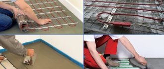
Installation sequence
Let's move on directly to the installation of the heated floor and temperature sensor.
First you need to determine the location of the thermostat, which will be located outside. It is most often located at a height of about 1 meter from the floor. Its mounting is similar to a regular socket.
Then you need to make grooves or grooves for laying two plastic pipes.
One for the power wire leading to the heating element, the other for the electrical wiring of the sensor. The tube for the temperature sensor will be located on the floor. Such a gasket will make it possible to carry out repair work without removing the tiles, at least to replace control elements.
It is not possible to completely replace the heating element if it is installed in a screed. It is important that when laying a pipe or cable corrugation there are as few bends and turns as possible. This will simplify the replacement of a failed temperature sensor in the future.
The next step is thermal insulation, it is performed individually for different types of heating elements, for example, for a heating cable it is used as a damper tape or other insulation, the thickness of which is at least 1.5–2 cm.
After this, the heating element is installed and secured with wires being connected to the thermostat box.
Installing and connecting a heated floor temperature sensor has its own subtleties. In order to prevent solution from getting inside the tube where the sensor is located, its end on the floor is securely sealed with electrical tape or tape. It is not recommended to connect the entire system through an outlet; it is better to supply power from a circuit breaker and through a contactor (starter).
The temperature sensor should be installed at a distance of 0.5 to 1 meter from the wall on which the thermostat is installed, and also exactly in the middle between two adjacent turns of the heating cable. After installation, it is recommended to secure the temperature sensor with mounting tape or foil tape.
If a film heated floor is being laid, the temperature sensor must be installed under the heater sheet, as shown in the photo below. Please note that thermal insulation must be laid under the temperature sensor, otherwise the heating system will not be effective.
Important point! The location of the temperature sensor should be selected so that it is away from other heating sources. Otherwise, errors will occur and the warm floor will not work as it should.
The connection diagram for the heated floor temperature sensor is as follows:
Before making a screed, you need to check the functionality of the warm floor and the temperature sensor itself. As a rule, the resistance of both elements is measured. The system is considered operational if the resistance differs by no more than 10% from the passport data.
In order for the assembled circuit to be as safe as possible, it is recommended that in rooms where electric floor heating is carried out, protective shutdown devices are installed, which, in the event of a breakdown, will disconnect the circuit from the voltage, thereby protecting a person from falling under electrical potential. In damp areas this can be deadly.
Manifold connection to the boiler
The process of connecting a warm water floor with a comb is very simple and boils down to connecting the pipes of the heating circuits to the collector, and the collector itself to the boiler. However, there are differences in the configuration of the collector. This is what we will consider in this subsection.
The collector must be installed in such a way that it is convenient to connect the heating circuit pipes to it. So, install shut-off valves on the collector. Connect the side outlet to the pipe for both supply and return.
If you buy a ready-made manifold kit, it will already have all the necessary valves, even at the outlets of the pipes going to the boiler. The presence of taps will allow you, if necessary, to carry out repairs or temporarily disconnect one of the circuits. If you assemble the manifold yourself, then the connection of each element is assembled using a compression fitting. As a result, the heated floors will be connected to the boiler through the manifold.
To automate coolant temperature control, the following set of equipment is additionally installed in the collector:
- Pumping and mixing unit, which includes a three-way mixing valve.
- For forced circulation pump.
- Drain tap.
- Air vent.
So, instead of shut-off valves, install thermostatic control valves on the manifold. Their design contains a thermal cylinder with paraffin, which, based on the air temperature in the room, narrows or expands. These actions set the capacity of the thermostatic valve. As for the pumping and mixing unit, the principle of its operation was written above.
So, we have looked at the basic and working diagrams for connecting a warm water floor. As you can see, knowing how to properly install a water floor is not enough. It must be connected correctly. We hope that this article will help you understand the intricacies of this work. And if you already have personal experience, then leave reviews and comments at the end of this article regarding the water heated floor connection diagrams you use.
Schemes of pumping and mixing units
Pumping and mixing units are assembled in several ways, the difference lies in the connection of the pump and in the form of a valve.
Node connection diagrams
Pump-mixing unit for heated floors.
With series pump connection
When the pump is turned on, only the coolant is prepared according to a sequential scheme and ensures its movement through the loops. Despite the need for two separate devices for pumping liquid through the primary and secondary circuits, this scheme is more technologically advanced.
It has increased performance than parallel connection. Therefore, professionals often use this option when installing heated floors.
However, for the efficiency of the floor during such an assembly, the correct calculation and settings, as well as the accuracy of the drawn drawing, play an important role.
With parallel
The advantage of a parallel circuit is that only one device is required to pump water through both circuits. This greatly simplifies the assembly process, but a more powerful unit is required.
If the mixing device is planned for a small heating system, then a parallel arrangement is recommended. Since when assembling such a structure with your own hands, fewer problems occur, it is therefore easier to avoid serious errors. But for large areas of heated floors, this scheme is not suitable - low productivity and efficiency.
System elements
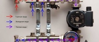
System elements
All schemes are united by ease of operation, the possibility of self-assembly, as well as the location of the main elements. The supply and return are located on the left side, and the manifold with combs is on the right. The differences between the schemes lie in the addition of some details. More often, the collector is located near the mixing unit, less often - at a distance, which may be due to a lack of free space or the planning features of the room.
The composition of the components depends on the material of the pipes used - cross-linked polypropylene, metal-plastic, corrugated stainless steel or copper.
The following elements are used in the scheme:
- Shut-off valves in the form of ball valves. They do not participate in the regulation of the main indicators of the coolant - its temperature and pressure, but are necessary during repair work when it is necessary to turn off individual components of the system.
- An oblique filter designed for mechanical water purification. It is used in the system if there is no confidence in the purity of the water used. Such a filter will not allow solid particles to enter the tuning device, thereby ensuring correct operation of the system and extending the life of the valves.
- Thermometers that provide visual control over the temperature of the water inside the circuit. Some models are equipped with a probe that is in direct contact with the coolant. Thermometers are liquid, mechanical and digital.
- The thermostatic valve is the main control element of the mixing unit. A thermostatic head is placed on top of it. When the temperature of the coolant changes, the head mechanically acts on the thermal valve. If the temperature is exceeded, the valve closes, and when the temperature drops, it opens.
- A bypass for cold water selection is a jumper that is formed between the supply and return pipes using plumbing tees. To fine-tune the coolant pressure, a balancing valve is installed on the bypass, which will ensure optimal operation of the system and its quietness.
- The optimal speed of water movement through the pipes is ensured using a circulation pump.
Supply choke
The two-way valve system is the simplest to implement. Control of the temperature of the water entering the pipes of the system is carried out thanks to a thermostatic head mounted on the valve and a liquid sensor. The opening and closing of the valve occurs thanks to the head, which passes hot water from the boiler into the circuit or cuts it off.
Thus, water from the “return” flows unlimitedly, and hot water only when necessary under the control of the valve. This prevents overheating of the heated floor and extends its service life. The low capacity of the two-way valve ensures smooth regulation of water temperature, eliminating sudden changes.
Three way throttle
Unlike a two-way valve, a three-way valve mixes water of different temperatures inside itself. This element combines a supply bypass valve and a bypass. The peculiarity is the ability to adjust the amount of hot and cold coolant for mixing, thanks to the damper located between the hot water pipe and the “return”.
Such valves have disadvantages. There is a possibility of supplying very hot water based on a signal from a temperature sensor, which, due to a sharp drop, can provoke an increase in pressure in the pipes and a violation of the integrity of the circuits. The large capacity of a three-way valve can cause a sharp drop in water temperature in the circuit even with a minimal adjustment of the device.
Coolant temperature requirements
The heating system for underfloor heating is a rather complex set of equipment, the correct assembly and configuration of which largely determines the correct functioning of the entire heating installation. For example, if a boiler is designed to supply a coolant of 70-900C to the radiators, then in underfloor heating circuits operating in parallel in the same rooms, the temperature of the circulating fluid is allowed no higher than 45-500C (max 550C). The exact temperature parameters are derived through engineering calculations of the underfloor heating system. They are designed to ensure the treatment of water in the pumping system in such a way that the heating of floor surfaces, taking into account the structure and material of their coatings, does not exceed:
- in premises with long-term stay of people (offices, residential) – 290C;
- in auxiliary rooms (storage rooms, corridors, dressing rooms) – 300C;
- in bathrooms, bathrooms, swimming pools - 320C.
In addition, the setting of the mixing unit will be performed most optimally if it is possible to achieve a temperature difference between the supply and return of the TP of 5-150C. A decrease in the thermal gradient (Δt) requires an increase in coolant flow, as a consequence of an increase in its circulation rate, which leads to hydraulic losses. A high temperature gradient is already felt tactilely, like a difference in heating of the surface of the floor covering, which causes a certain discomfort.
Figure 2
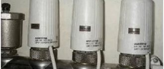
Mixing valves
Depending on the desired effect, there are various connection methods. Each of them necessarily involves the installation of mixing valves. These devices are necessary to connect hot and cold water. The latter is supplied from the heating circuit, the former from the boiler. The system can be adjusted automatically or manually, which requires additional installation of a control servo drive. There are two types of mixing valves.
Two way servo
This servo is also called the feed servo. Its main difference from conventional valves is the ability to conduct water in only one direction. If the valve is reinstalled incorrectly, it begins to malfunction and quickly fails.
“Feeding” – conducts water in one direction only
A ball or a special rod is used as a locking part for it. Adjustment is made either by turning the ball or moving the rod. Electric drives are used to carry out these manipulations.
The most popular method is a thermostatic head equipped with a water sensor that regularly monitors the temperature of the coolant. Taking into account the received data, the head turns the valve on or off. So, coolant is supplied from the return line regularly, and from the boiler - only as needed.
The operating principle of the device explains the main advantage of the manifold, which is equipped with a supply valve. Floors with this equipment do not overheat, this significantly increases their service life. The low throughput of the valve creates a smooth adjustment of the coolant temperature; significant jumps in this case are excluded.
Supply valves are characterized by ease of installation and subsequent operation. They are quite often found in the circuit of homemade manifolds for heated floors, but they have some limitations in application. It is not recommended to install two-way devices in systems that operate in rooms larger than 250 square meters.
Three-way systems
Three-way elements are designed differently. This equipment combines the operation of a bypass supply valve and a bypass valve. The valve consists of a body with one supply and two outlets. For regulation, either a rotating ball or a special rod is used.
The peculiarity of this type of device is that the adjusting part completely blocks the flow and distributes the incoming water, mixing it. The temperature is adjusted automatically; for this, the valve has a drive system that receives signals from various sensors.
Such valves have servo drives
Typically, three-way valves are equipped with actuators that are controlled by thermostatic sensors or weather-compensated controllers. The servo drive activates the locking mechanism, which is installed in the required position to obtain the required indicator of the heated coolant and return.
Weather-dependent controllers are required to regulate system power based on the weather. For example, during a cold snap, the room will begin to cool down much faster, meaning it will be much more difficult for the heating system to do its job.
To make the task easier, you need to increase the consumption of coolant and increase the temperature. The main disadvantages of three-way elements include significant throughput. Under these conditions, even a slight shift in adjustment can lead to a sharp change in water temperature.
Three-way elements are used for manifolds installed in rooms larger than 250 square meters. m and systems with a large number of circuits. Moreover, they are used for structures that are equipped with weather-sensitive sensors that determine the required floor temperature taking into account atmospheric conditions.
Design and varieties
All mixing units as standard consist of:
- control and thermostatic valve;
- pump;
- thermostatic head;
- temperature limiter;
- built-in temperature sensor.
Manifold for warm water floor
There are two types: 2-way or 3-way valves. They mix the hot and cold water coming back from the underfloor heating system, thus ensuring its continuous circulation. A two-way valve (also known as a supply valve) has a thermal head with an installed liquid sensor.
The sensor non-stop checks the temperature of the supplied liquid and, if necessary, cuts off its supply from the boiler. A hot portion of water will be supplied by the valve only after the water has cooled down, mixing with the return. For rooms up to 200 square meters, it is preferable to install two-way units.
Three-way valves have a much higher flow capacity than two-way valves. In small rooms, unfortunately, they can leak hot water into the general system if they open completely. This, in turn, can provoke sharp intra-temperature jumps and pipe rupture. Therefore, three-way systems are ideal for large, spacious homes where the systems have a large number of circuits and weather controllers are used.
Mixer operation
There are models on the market that differ in type of consumption:
- designed for installation on an individual standard manifold;
- individual-group node for connecting a high-power user.
The latter can be used to connect several consumers with a relatively low power of each of them, or it can be designed for significantly higher power with 2-12 outputs.
Device installation
The manifold for a warm water floor is mounted according to the following scheme:
- It is necessary to install a frame under the device. It is mounted directly on the wall in a horizontal position or in a specially prepared niche. When choosing a location for installation, you should be guided by the availability of free access to the device to connect the required number of pipelines. Also, a special cabinet is often used to mount the device. In this form, the device can fit into any room.
- Connection to the heating boiler. The coolant is supplied to the system from below, and the return is placed at the top. You also need to install cut-off balls in front of the frame. A circulation pump is installed behind the taps.
- The bypass valve is being installed. It must be equipped with a temperature limiter. Behind this unit the distribution comb is installed.
- Pipelines are being laid to the heated floor. The elements through which coolant will flow into the system are placed on top. Pipelines from underfloor heating are installed from below.
- If you intend to install the device yourself, you must connect shut-off valves that are equipped with a thermostat to the distribution comb. When installing a ready-made kit, this is not necessary.
- The collector is connected to the heating system using compression fittings. This element consists of a clamping ring, a support sleeve and an intermediate nut.
- Pressure testing of the collector. After installing all structural elements, it is necessary to check how tight the resulting system is. To do this, the unit is connected to a circulation pump. With its help, pressure is built up in the system. The water circuit is left in this form for a day. After this time, the pressure is checked. If it has not changed, then the installation was successful.
Norms and restrictions
Warm water floor is a low-temperature heating system. According to existing standards, the maximum temperature level of the coolant should be +55 degrees. During operation, standard heating usually ranges from +35 to +45, with the floor heating up to +26 - +31. The standards for different premises differ:
- for bedroom, kitchen, living room - +26;
- for bath, toilet, hallway—+31.
Liquid circulates through the floor lines using a pump. In addition, it allows you to regulate the heating level in the room. You need to select it based on the speed of water movement. The maximum permissible for hydrofloors is 0.6 m/s.
The difference between the heating of water at the supply and outlet should not be within 10 degrees.
Types of floor heating systems
There are two fundamentally different systems; let’s look at their strengths and weaknesses. The choice of scheme will affect the comfort of living in residential premises, keep this in mind when making a decision, take into account not only the technical parameters of various schemes, but also the features of the premises and existing heating systems.
Water heated floor
Allows for uniform floor heating and is compatible with some existing heating systems in older buildings. Disadvantages include the complexity of equipment and installation work and the high estimated cost. In addition, the water system reduces the height of the room by at least 10 cm due to the concrete screed. To create an installation diagram, the room is divided into separate sections, taking into account the size and configuration of the floor; each circuit must have approximately the same length of pipes, otherwise the heating will be uneven over the area. Depending on the construction technology, a water floor can have several installation schemes.
- On a concrete base. It consists of a layer of thermal insulation on a concrete base, a metal mesh for laying pipes, pipelines, a top screed and a finishing floor covering.
- Polystyrene. A more modern method of laying a water-heated floor, there is no need to do a cement-sand screed. Special polystyrene plates with places for fixing plastic pipelines are laid on the thermal insulation layer. The finished wiring is covered with gypsum fiber boards, on which the finishing flooring is laid.
The general disadvantage of water floor heating is that emergency situations have very serious consequences. The most complex elements of a water heated floor are the mixing unit and the manifold.
Description of types of mixing units
The mixing unit ensures constant and balanced circulation of heated water along the laid circuits, changes the speed of movement, and independently maintains the set temperature of heating the floor and coolant. Depending on the design features, it can have several types:
- with series connection of water pump and two-way thermal valve;
- with series connection of water pump and three-way thermal valve;
- with a series connection of a water pump, a three-way thermal valve operates with flows converging in one unit;
- with parallel connection of a water pump, two-way thermal valve;
- the water pump is connected in parallel, the thermal valve is three-way.
Mixing unit for heated floors
Each scheme has its own characteristics; selection is carried out taking into account technical parameters and the number of heating circuits.
Piping for radiators and heated water floors
Distribution manifolds
Designed to connect all heating devices of the floor heating system in one place. Depending on the nomenclature and quantity of additional special equipment, they can be simple or advanced. Simple ones do not have any fittings and serve only to connect fittings. Advanced ones have control sensors, execution devices, measuring instruments, etc.
Infrared radiometer
This type of pyrometer operates based on the radiation method and in a limited range of infrared radiation.
For ease of use, the device is equipped with a special laser pointer.
It helps to point the device at a specific place on the part and measure its temperature.
An infrared pyrometer consists of the following components:
- diaphragm;
- lens;
- copper casing;
- frame;
- lamp;
- light filter;
- eyepiece;
- heat;
- millivoltmeter
The operating principle of the device is based on capturing thermal radiation coming from a hot object and focusing it with a sensitive element connected to a thermocouple.
The device works like this:
The turned on pyrometer is aimed at the part being studied so that it is in the lens and completely blocks other objects from the human eye. The eyepiece moves and achieves maximum image clarity
It is important to use a filter. It will not only allow you to take measurements more accurately, but will also protect your eyes from the harmful effects of bright light. Thermal radiation reaches the sensitive element of the device
It is made in the form of a platinum plate. Thermocouples are soldered to it, which heat up depending on the temperature of the object. It is measured and the result is displayed on the device screen.
Floor standing gas boiler
It is not recommended for initial consideration. The reason for this is the lack of the following mechanisms in the design:
- circulation pump;
- additional cranes providing dry repairs;
- expansion membrane tank;
- separate group of valves at the heater outlet.
Of course, models are now being produced with all of the above. There the tying becomes easier. In any case, initially everything has to be recorded on the plan. And draw up the scheme with experienced craftsmen.
Floor standing gas boiler
After all, you will have to use a closed system with a specific pressure. The value must be redundant to function. Nuances are discussed at the planning stage.
Separate requirements for gas equipment parameters
Heating using natural resources will have to be chosen correctly. Only in this case it is possible to avoid unnecessary negative emotions, waste of time, and loss of money.
All requirements are established by state standards. Their meaning is strict and unchanging. Linking directly to the area is due to technical capabilities. Which:
- 60 kW. Suitable for 2 meter ceilings. The room has 8 cubic meters of air volume;
- The boiler room is ventilated through three air exchanges. Combustion takes oxygen from a separate source. Kitchen window with window. The air flow is stable in both cases;
- There is a protective layer between the fasteners and the equipment itself. This is usually a sheet of metal. Its role is to prevent fire when the temperature rises during operation;
- the distance to the wall is at least 3 cm. The front side of the boiler allows it to be serviced on one square meter. From the sides, the distance from the unit is at least 60 cm;
- horizontal supply to the chimney no more than 3 meters. The diameter of the pipes used is the same as the heater. It's even better to connect a larger value. Then the hood is tougher.
Essentially, such requirements are checked by the company supplying gas to the house/building. It also allows the connection of such a device to a common highway. In the case of a gas holder, the owners of the premises check themselves. But it is worth remembering that their own lives are at stake.
There are no specific ones indicated for strapping. The gas boiler is connected to the floor heating system and then operates. Ensuring efficient work is compared with comfortable living conditions. An incorrect connection will affect the rest of the house.
The owners themselves are interested in proper connection by checking each parameter. It is better to place all aspects on the plan at the preparatory stage. Then it's easier to check.
We recommend: What is a self-leveling heated floor?
How it works
The three-way valve is installed in those sections of the pipelines where it is necessary to divide the flow of circulating fluid into 2 circuits:
- with variable hydraulic mode;
- with constant.
In most cases, a constant flow is required by those who are supplied with liquid of high quality and in designated volumes. It is regulated in accordance with quality indicators. As for the variable flow, it is used for objects where quality indicators are not the main ones. The quantity coefficient is of great importance there. Simply put, the coolant is supplied there according to the required quantity.
Note! Shut-off valves also include an analogue of the device described in the article - a two-way valve. How is it different? The fact is that the three-way option works on a completely different principle. The rod included in its design is unable to block the flow of liquid, which has constant hydraulic parameters
The rod included in its design is unable to block the flow of liquid, which has constant hydraulic parameters.
The rod is open all the time, it is adjusted to a particular volume of liquid. Consequently, users will be able to get the volume they need, both in terms of quantity and quality. In general, this device is unable to stop the flow of fluid to a network in which the hydraulic flow is constant. In this case, it may well block a flow of variable type, due to which, in fact, the possibility of adjusting the flow/pressure arises.
And if you connect a pair of two-way devices, you can get one, but three-way. But it is necessary that both work in reverse, in other words, when one valve closes, the next one must open.
Using drives
In addition to the thermostatic head, the valve can be controlled in other ways. The first of them is manual, when the depth of pressing of the rod is determined by turning the handle outside the body. Not the best option and is only suitable if the temperature of the water entering the pipes is constant. Another option is control using a servo and electric drive, receiving commands from the controller. To work together with different drives, another type of valve is used - rotary valves, whose device is shown in the figure:
This 3 outlet valve is very similar to a regular motorized ball valve
There is a certain similarity here with a ball valve, only the working rotary element has a different hole shape to allow coolant to flow in two directions at once. The operating principle here is simple: the axis rotates to the required angle, rotated by the drive. The latter is controlled by a controller that receives impulses from one or more sensors. Typically, valve actuators are installed in complex or automated heating systems with weather control.
conclusions
The operation of a water heated floor pump is comparable to the functions of the heart in living organisms - it promotes the movement of coolant within the system, allowing the operating temperature of the pipes to be maintained in a normal state without excessive cooling.
Maintaining constant pressure and flow stabilizes the functioning of the heated floor and helps overcome the hydraulic resistance of pipelines of complex configuration and small cross-section.
A correctly selected circulation mode makes the system operate efficiently, economically and extends the service life of all elements of the water heated floor. Date: September 25, 2022
Technical characteristics of radiators
Competition in the radiator market is extremely high, so there are not many manufacturers producing and selling cast iron batteries on the domestic market.
Before purchasing, you should familiarize yourself with the technical characteristics of the most common cast iron heating radiators. This will allow you to choose exactly the products that are most suitable for the planned or existing heating system.
Manufacturers of cast iron batteries
If German batteries are particularly sophisticated, then the products produced by ChAZ are not inferior to them in their technical characteristics.
Moreover, the batteries of the Cheboksary Aggregate Plant are the best among Russian manufacturers . The main factories that offer cast iron batteries are:
- Adarad (Türkiye);
- Cheboksary Aggregate Plant (Russia);
- Viadrus (Czech Republic);
- Demrad (Türkiye);
- Minsk Heating Equipment Plant (Belarus);
- KIRAN (Ukraine);
- Konner (China).
There are many European manufacturers of cast iron radiators, but their products are not competitive. It has a high price, and the quality is comparable to domestic samples.
Devices for organizing heating in a vintage style are offered by a St. Petersburg manufacturer:
Overall dimensions of radiators
The sizes of radiators in the post-Soviet space were standardized. The distance between the center of the axes of the supply and discharge coolant pipes was 300 or 500 mm.
The depth of the sections and their width were not regulated and differed from one manufacturer to another. Most modern radiators are also adapted to these standards.
Cast iron radiators can be selected to any size required for placement under a window sill or in a wall niche
The most common model of cast iron batteries is MS-140. This is what stands in most Khrushchev and nine-story buildings built in the 60-80s of the last century.
The dimensions of its section are: center distance – 500 mm, total height – 588 mm, width – 93 mm, depth – 140 mm.
The wider the sections, the fewer of them are required to gain the required power, which means the number of potentially problematic joints is reduced.
The main goal of creating cast iron radiators with different dimensions is to enable the buyer to choose a model that best fits into the interior. Batteries with a total height of up to 400 mm, for example, fit perfectly into rooms with low window sills.
Appearance and structure of equipment
Almost all cast iron radiators are stacked. They are made of gray cast iron and consist of detachable sections that are connected using nipple bushings. This design allows you to form a solid battery of the required length and power. Paronite gaskets are placed between the sections.
Multi-column cast iron radiators are difficult to clean externally from dust, which significantly reduces the heat transfer of the batteries
In the horizontal plane between sections, water moves in only one direction. Vertically, the fluid flow occurs through one or more channels. With their number, the area of radiators and their power increases.
The disadvantage of multi-channel sections is their high cost and increased hydrodynamic resistance.
The classic "accordion" look of radiators is becoming a thing of the past. Due to the predominantly radiant method of heat transfer, manufacturers are seeking to increase the area of the battery façade, which results in a flatter appearance. An example is the Konner Modern500 model.
Radiators made of cast iron from the Konner Modern series, at a low cost, have a beautiful polished surface identical to aluminum panels
A number of imported models have decorative patterns on the surface, but the cost of such batteries is incomparably high.
The weight of cast iron sections is quite large. The need to maintain wall strength and maximum heating surface area does not allow engineers to greatly reduce the weight/power ratio. The weight of the section of the standard MS-140 model is 7.1 kg.
The unwinding of sections of cast iron radiators must be carried out gradually and synchronously from above and below, otherwise the threaded connection can be irreversibly damaged
The large mass of cast iron radiators also requires good fastenings. Batteries usually do not have special design elements for fixing to the wall. They are simply hung on special brackets, which are pushed into the spaces between the sections. There are also special feet for installing batteries on the floor.
Thermal power of devices
The power of radiator equipment is characterized by the ability to release thermal energy at the maximum operating temperature of the coolant. This indicator in cast iron radiators depends mainly on their surface area.
Depending on the model, the power can range from 80 to 200 W per section. These are passport values, which in real conditions can be much lower.
The recommended power of heating radiators is approximate. For regions with severe frosts, it may differ greatly from the standard
There is a classic formula for calculating the required power of a cast iron heating battery based on the volume of the room: for every 25-30 m3 radiators with a total capacity of 1 kW should be installed. If there are 2-3 external walls, this indicator should be adjusted towards increasing power. For more information on how to calculate the required number of batteries for heating, read this material.
To enhance heat transfer due to convection, some models of cast iron radiators are equipped with ribs between the columns. This design can increase the power of the section by 20-40%. You should remember the need to regularly clean such jumpers from dust.
Other equipment characteristics
When choosing radiators, you should pay attention to their other characteristics:
- maximum working pressure;
- coolant volume in the section;
- maximum coolant temperature.
All of the above indicators for cast iron batteries are higher than for aluminum and bimetallic counterparts. But the characteristics may differ for different models, which should be taken into account when selecting the components of a new heating system.
Models of the Minsk Heating Equipment Plant
Maximum settings are especially important when replacing batteries connected to a central heating system. When it is pressurized in the fall, excess pressure is supplied to the pipes, which can rupture unsuitable radiators.
This can result in flooding of both your own and the apartment located below, so special attention must be paid to the operating values of pressure and temperature of the coolant