The defining task when designing an autonomous heating system is the uniform distribution of the coolant. This task in the heat supply system is performed by a control and regulation unit - the distribution manifold.
The uninterrupted operation and reliability of the heating circuit largely depends on the correct choice of device, high-quality installation and connection. If you want to install a heating distribution manifold with your own hands, then you need to carry out calculations and design the wiring in advance.
We will help you resolve these issues. In the article, we examined the design of the collector group, identified the pros and cons of a heating system with a comb, and described the rules for the design and installation of a distribution unit.
The material is supplemented with practical advice on selecting components, assembling and connecting the collector to the heating system.
The role of the collector in heating
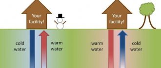
When arranging a water pumping unit, you must adhere to the rule: the total sum of the diameters of all branches should not be greater than the diameter of the supply main.
Let's apply this law to the heating system, but it will look like this: a boiler outlet fitting with a diameter of 1 inch is allowed for use in a double-circuit system with pipes with a diameter of ½ inch.
For a house with a small cubic capacity that is heated exclusively by radiators, this kind of system is considered productive.
For utility rooms, it will be enough to set the temperature to 10-15 °C; for living rooms, a temperature of up to 23 °C will be comfortable; in underfloor heating circuits – no more than 37 °C, otherwise the main coating may be deformed.
In practice, a private cottage is equipped with a more modernized heating circuit, where additional circuits are installed:
- heated floor system;
- heating of several floors;
- utility rooms, etc.
When a branch is connected, the level of operating pressure in the circuits becomes insufficient for high-quality heating of all radiators, respectively, and the comfortable atmosphere will be disrupted.
In this case, a balancing unit is installed for a branched heating main using a distribution manifold. Using this method, it is possible to compensate for the cooling of the heated coolant, which is typical of traditional one- and two-pipe schemes.
By means of equipment and shut-off valves, the required coolant temperature indicators are adjusted for each of the lines.
Operating principle of two-way valve
When using a connection diagram for a comb with a two-way valve for a heating floor, the design is equipped with a temperature sensor, it is located on the return line. The valve can be in an open or closed position, it depends on the rod that is controlled by the thermal head.
The operating principle of the device is determined by the opening of the valve, resulting in the flow of heated liquid from the boiler into the comb.
There it is diluted with cooled coolant, and then sent to the supply pipe. At this moment, the thermometer measures the temperature level of the liquid; if it is lower than required, the rod remains open.
When the desired temperature is reached, it closes and hot water stops flowing. When the coolant cools down in the heated floor, the thermal head raises the rod, thereby opening and resuming the supply.
The two-way valve is reliable, the possibility of breakage of the shut-off element is almost zero, so the risk of an excess portion of heated liquid entering the heated floor is minimal. However, it is worth saying that the control process - smoothness and accuracy - is inferior to three-way valves.
A manifold with a two-way valve can heat a room with a limited area - no more than 200 m2. The device is not suitable for heating large rooms.
Main characteristics of the collector system
The main difference between the collector and standard linear method of redistribution of the coolant is the division of flows into several channels independent of each other. Various modifications of collector installations can be used, differing in configuration and size range.
The collector heating circuit is often called radiant. This is due to the design features of the comb. When examining the device from the top point, you will notice that the pipelines extending from it resemble an image of sun rays
The design of the welded manifold is quite simple. The required number of pipes is connected to the comb, which is a round or square pipe, which, in turn, are connected to individual lines of the heating circuit. The collector installation itself is interfaced with the main pipeline.
Shut-off valves are also installed, through which the volume and temperature of the heated liquid in each of the circuits is regulated.
A manifold group, complete with all the necessary parts, can be purchased ready-made or assembled independently, which will significantly reduce the cost estimate when designing heating
The positive aspects of operating a heating system based on a distribution manifold are the following:
- The centralized distribution of the hydraulic circuit and temperature indicators occurs evenly. The simplest model of a two- or four-circuit ring comb can balance the indicators quite effectively.
- Regulation of operating modes of the heating main . The process is reproduced due to the presence of special mechanisms - flow meters, mixing unit, shut-off and control valves and thermostats. However, their installation requires correct calculations.
- Ease of maintenance . The need for preventive or repair measures does not require shutting down the entire heating network. Due to the sliding pipeline fittings mounted on each individual circuit, you can easily shut off the coolant flow in the required area.
However, there are also disadvantages to such a system. First of all, pipe consumption increases. Compensation for hydraulic losses is carried out by installing a circulation pump. It must be installed on all collector groups. In addition, this solution is only relevant in closed-type heating systems.
Criterias of choice
The number of collector outlets must correspond to the number of heating circuits.
The element model must be selected at the design stage. The number of outputs for the collector must correspond to the number of circuits. Due to the length of the routes and the pressure within the network, pumps are not used to force the flow of liquid. In private buildings where more than 100 meters are laid, additional draft must be created for pipes within the system. When installing heated floors, pressure drops also often occur.
A properly selected comb should balance performance characteristics. When choosing, they first look at the pressure indicators, as well as the temperature. Such an element can be of a simple or complex type; the second option is suitable for those who need a comb with auxiliary options. Innovative elements help you adjust and control temperature and other indicators.
Options with temperature sensors help determine in which rooms heat exchange occurs faster, where water provides less energy. Due to proper adjustment, liquid will not get where it is not needed.
When choosing, always take into account the material from which the comb is made. It can be cast iron, steel, brass or plastic. The ideal option would be cast elements that eliminate any leaks.
Modifications of collector units
Before you begin assembling the collector assembly, it is necessary to determine its functional load. The equipment can be installed in several sections of the heating main. Based on this, the necessary equipment, dimensions and level of automation of the work cycle are selected.
In fact, for the full operation of such a node, two devices are needed. Using a comb, the coolant is distributed along the contours of the central supply pipeline. The return collector channel is represented by a collection mechanism and the point of departure of the cooled liquid into the boiler.
The collector heating circuit is selected based on the calculation of the required functionality and installation location. The choice of material for making the device does not affect the number of significant mechanisms
Installation of a homemade distribution group may be required when installing water-heated floors or for preparing standard heating with radiators.
Distinctive features of both options are their sizes and components:
- Boiler room . The welded manifold group is made of pipes with a diameter of up to 100 mm. A circulation pump and shut-off valves are installed on the supply side. The return ring is equipped with shut-off ball valves.
- Warm floor system . Similar equipment is present in this mixing unit. With its help, it is possible to significantly save on coolant consumption, especially if additional flow meters are installed. Read more about the mixing unit in a heated floor system in this article.
Each of these solutions provides an individual installation scheme. Correct installation of all elements can be carried out only after detailed calculations of all operating point parameters.
The comb can be made of the same material as the pipeline. If it is different, adapters will be used to connect the collector
There are also differences in the required number of circulation pumps. In the boiler room, each line is equipped with this device. For heated floors, only one installation is provided.
Both distributor and regulator
At its core, a distribution comb is a centralized unit that allows the coolant to be distributed to its destination points. In a heating system, it performs no less important function than a circulation pump or the same boiler. It distributes heated water through the mains and regulates the temperature.
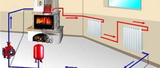
This diagram shows the general operating principle of a collector block consisting of two combs: through one, coolant is supplied to the system, and through the second it is returned
This unit can be called a temporary coolant storage tank. It can be compared to a barrel filled with water, from which the liquid flows not through one hole, but through several. In this case, the pressure of water flowing out of all holes is the same. This ability to simultaneously ensure uniform distribution of heated liquid is the basic principle of operation of the device.
Externally, the collector looks like an assembly of two combs, most often made of stainless steel or ferrous metal. The terminals available in it are intended for connecting heating devices to it. The number of such outputs must correspond to the number of heating devices served. If the number of these devices increases, the unit can be expanded, so the device can be considered dimensionless.
In addition to the leads, each comb is equipped with locking mechanisms. These can be two types of taps installed at the outlet:
- Cutting off. Such taps make it possible to completely stop the supply of coolant from the general system to its individual circuits.
- Regulatory. With the help of these taps, the volume of water supplied to the circuits can be reduced or increased.
The manifold includes valves for draining water and releasing air. It is also most convenient to place measuring equipment in the form of heat control meters here. In this case, everything that is necessary for the effective operation of this node will be in one place.
Why are there two combs in the manifold block? One serves to supply coolant to the circuits, and the second is responsible for collecting already cooled water (return) from the same circuits. All elements necessary for effective operation must be on each of the combs.
Distribution node design
There is simply no universal scheme for a radiant heating project. Each case is individual, which is why the unit is equipped with the necessary devices privately. However, it is worth familiarizing yourself with the general recommendations and rules.
Rules for installing the comb
Installation of the collector is not possible in an apartment. However, there is an exception to the rule - in some houses, when all communications are installed, additional valves are installed, through which the heating circuits are connected. This device allows for individual wiring of the collector.
The beam scheme is not suitable for city apartments in multi-storey buildings, because the riser is common to all premises (+)
The schematic arrangement of the heating should be designed in such a way that the location of the Mayevsky tap is on the comb. This option is considered optimal, because over time, accumulated air will need to be released from the circuits.
Features of the beam group
The radial wiring group has many nuances, but some of them are also typical for heating of other modifications.
Features of the comb system:
- The circuit must include a compensation tank with a volume of more than 10% of the total volume of the coolant.
- The optimal location of the expansion tank is on the return pipeline in front of the circulation pump, since the temperature regime is lower here.
- If a thermo-hydraulic distribution is used, the circuit is designed so that the tank is located in front of the main pump, which is responsible for the forced movement of water in the boiler piping.
- The circulation pump is installed in a strictly horizontal position. If you do not adhere to this rule, at the first air lock, the device will lose cooling and lubricant.
The distribution group can be assembled from various materials: polypropylene or metal. The selection is made based on work skills and the availability of tools for connecting parts.
The optimal heating temperature for radiators in a private cottage is 55-75 °C, pressure up to 1.5 atm. The operating mode of the warm floor circuit warms up to 40 °C. Based on these characteristics, the degree of stability of the pipes is selected
The process of selecting pipes for installing a distribution group is also considered important.
The main factors taken into account when choosing contour elements:
- Purchase of pipes only in coils . Due to this, connections are not made in the wiring installed under the concrete screed.
- Heat resistance and tensile strength must be determined individually based on the technical data of the heating system.
Due to the predictability of the operating characteristics of autonomous heating, polypropylene pipes can be used. They do not have unwanted connections and are sold in continuous 200 m lines.
The material is heat-resistant and can withstand temperatures up to 95°C with a permissible burst pressure of 10 kg/1 cm2.
Stainless steel pipe is highly flexible. The bend radius can be equal to the diameter of the product. Installation is carried out according to the following scheme: the pipe must be directed into the fitting and secured with a nut
For a multi-story building, it is preferable to choose a corrugated pipe made of stainless steel.
This material shows excellent technical capabilities to cope with such a load:
- heated coolant up to 100 °C, which is more than enough for the heating circuit;
- pressure up to 15 atm;
- fracture pressure up to 210 kg/1 cm2.
Fittings designed for polypropylene can be plastic or made of brass. The fitting connection is equipped with a locking ring, which is threaded onto the pipeline.
An important characteristic of polypropylene pipes is the memory of mechanical processing, which results in plastic deformation of the substance.
For example, when stretching pipes with an extender and installing a fitting into the connector, after a certain time the pipe will return to its previous state and crimp the part. The contact can be secured with a locking ring.
Heating manifold calculation
Initially, to manufacture a thermohydraulic comb, you will need to calculate its main parameters - length, cross-sectional diameter of the pipes and the number of branches of the heating main. You can calculate these characteristics yourself or use special software.
The hydraulic separator will fully perform its functions only if the rule of three diameters is observed. The law is as follows: the diameter of the mounted hydraulic arrow must be three times greater than this parameter for the pipes (+)
The hydraulic balance of the structure is the main condition that must be met. Applying the rule of three diameters for a hydraulic separator, it is necessary to perform the following action - sum up the cross-sectional diameter of the connected circuits.
As a result, we get an amount equal to the diameter of the main pipe connected to the supply line. Using this principle reduces the likelihood of imbalance of the entire heating system.
A special cabinet or housing is used as a place for the distribution unit. When arranging the system, it is necessary to adhere to the permissible minimum distance between two heat-conducting input and output lines - 6 diameters.
All calculations of the thermohydraulic comb design are based on three important rules: maintaining the correct distance between the incoming and outgoing lines, the cross section of the comb and the distance between the contours is equal to three diameters (+)
The issue of correct selection of the circulation pump performance is also relevant. To do this, it is necessary to calculate the specific rate of water consumption of the system and, based on the results, select a pump.
If the circuit is complicated by several combs, the calculation is performed for each individual circuit and in general for the entire system.
Self-assembly of equipment can be carried out using a pipe with any type of cross-section. This aspect does not affect the operation of the device and does not increase local losses. They will be compensated by the circulation pump.
Scope of application
There is no universal limiter design. Therefore, they choose it based on the scope of application. Euro models are suitable for winter. With their help, the opening of the sash is fixed at a minimum distance. This space is enough to ventilate the room and not cool it more than necessary.
The absolute opposite is the domestic model. It has a large distance between the grooves, which is why it opens to a greater length and provides complete ventilation. Suitable for full ventilation.
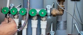
Rules for selecting components
Having completed all the calculations, the next step is to select the required set of mechanisms. The simplest set consists of shut-off valves. However, with such a device it is difficult to regulate the power of individual heating lines.
To solve this problem, crane axle boxes are installed on the feed comb, through which smooth adjustment is possible. Rotameters are mounted on the return manifold.
The collector parameters must be sufficient for convenient access to shut-off and control valves. The average range between the contours is 100-150 mm, the center distance between the feed and return combs is 250-300 mm
For warm water floors, the configuration scheme will be different.
For assembly you will need the following elements:
- Shut-off and control valve. Installation is carried out on connecting pipes. With the help of this fittings, the flow of coolant is completely or partially stopped. It is recommended to use automatic modification.
- Rotameters . Such elements are mounted on the return collector. They perform a similar function as the previous element, only in the return pipeline.
- Mixing unit . By mixing hot and cold water flows, the specified heating operating mode is optimized.
The manifold kit is necessarily equipped with a safety group headed by a pressure gauge, air valve, thermostat and circulation pump. It can be supplemented with servo drives, the control of which is reproduced through the control electrical unit. Thus, the operation of the system can be automated.
Automatic temperature control of TP
Automatic adjustment of a heated floor can be carried out thermomechanically or electronically using electromechanical actuators that control the operation of shut-off valves.
Thermomechanical control system
It is based on the operation of thermostatic valves or taps with thermal heads that respond to changes in coolant temperature. Various models of such shut-off and control valves are offered today by many manufacturers, for example, Oventrop. However, regardless of the name and type of thermosetting substance used in them (liquid or gas), these are thermomechanical self-regulating mechanisms that are most appropriately installed to control the temperature of one, individual circuit.
The operating principle of thermal valves is simple, which makes them very reliable and fault-tolerant. A copper, brass or bronze core installed in the device body, heated by the passing coolant flow, transfers the temperature to the thermosetting filler. In turn, the thermosetting element, which increases in volume, pushes the core, which, by moving the valve, gradually blocks the circulation of the heated liquid.
The thermostatic valve for heated floors, in addition to being installed on the distribution comb, can be mounted in a separate “unibox” type assembly. Such assemblies also include automatic air vents, which, together with thermostats, are placed in compact boxes (boxes). The use of a “unibox” allows you to adjust the temperature in a separate branch of the TP without being tied to bulky manifold cabinets, which is especially convenient with a small number of circuits.
In addition, thermomechanical floor heating controllers can have remote air sensitive elements. They allow you to configure them to control the flow of coolant not according to its temperature, but according to the air temperature in the rooms. The principle of their operation is the same, only the thermosetting substance is much more sensitive. It is advisable to install an air thermal head for simultaneous control of several circuits in one room, where water underfloor heating is the only source of heating.
Electronic control system
It consists of electronic thermometers, a controller and electric drives (actuators, servos). Electric drive mechanisms can be attached to the mixing heads of conventional control valves (valves) or be part of their design. The change in coolant supply intensity is carried out in accordance with specified threshold values. The measuring medium for the temperature sensors of the automatic floor heating temperature controller can be both the coolant and the air in the premises.
Subtleties of self-assembly
Before manufacturing the collector, it is necessary to draw up a diagram showing the location of all the elements of the assembly. It is better to choose steel pipes with a square cross-section as the manufacturing material. This type is easy to process, which significantly reduces labor costs for installing pipes.
Manifolds made of profile pipes are used in the heating circuit of objects with a large number of circuits and a hydraulic separator. Square pipe parameters – 80*80 or 100*100 mm
The step-by-step process for producing a prefabricated distribution structure is as follows:
- Marking and cutting of the main body . According to the design diagram, it is necessary to mark the profile pipe. Using a gas cutter, holes are made in the marked areas.
- Preparing connections . The pipes are threaded using a die.
- Staffing . Next, the prepared pipe sections are welded to the body. Their fixation must be done by tack spot welding. Then, during the main welding, the workpieces are welded along the edges.
- Fastening elements . Brackets for fastening are welded to the block.
- Cleaning and finishing . After cleaning, the body is primed and coated with heat-resistant paint for metal products. The supply and return circuits are painted in two different colors for ease of identification.
If polypropylene pipes are used for production, you should pay attention to the presence of a reinforcing layer in them. In its absence, the plastic structure may be subject to deformation due to the current temperature conditions.
For those who do not have special tools, you can assemble a comb from separate ready-made elements. It is better to select components from one company.
Advantages
When using underfloor heating combs, you can get a number of advantages:
- Energy savings compared to conventional radiator use. Its value can be from thirty to fifty percent.
- High degree of safety during operation. There are no fire-hazardous open heating elements.
- Greater durability. The service life can be two decades or more.
- High comfort of heating the apartment and the absence of areas with uneven heating.
- The aesthetics of the design used. The system takes up little space and is usually mounted in a special small cabinet.
- Hygiene. Keeping the floor warm makes wet cleaning easier and eliminates the destructive effects of excessive humidity. This, in turn, makes it impossible for fungi or mold to form.
- Safety from burns. In the absence of such a heating control system, hot water can be used. When touching pipes, not only children, but also adults can get burned. A comb for heated floors allows you to qualitatively regulate the temperature of the coolant, avoiding its excessive heating.
Installing a comb in the heating system
The primary task is to check the distribution manifold for tight connections. The installation is implemented according to the design scheme. Depending on the material used to manufacture the main unit, the connection conditions are determined.
In complex systems where there are many circuits for various purposes, it is necessary to install a vertical pipe - a hydraulic arrow. With its help, pressure equalization and distribution of forward and reverse flows of coolant are realized
The choice of connection technology depends entirely on the modification of the device used.
In addition to maintaining the level, during installation you must follow the following rules:
- electric and gas boilers are connected to the upper or lower pipes;
- a circulation pump is mounted at the end of the structure;
- the circuits can be connected at the top or bottom of the comb;
- indirect heating devices and boilers operating on solid fuel must be connected to the distribution group on the side;
- the entire hydraulic separation unit for the underfloor heating system is placed in a protective box - this reduces the risk of damage to the constituent elements of the collector.
At the final stage, it is necessary to carry out a control start-up of the heating in order to timely identify hidden or obvious deficiencies in the design.
Additional information on organizing a radiant heating system using a distribution comb is provided in this article.
Planning stage
To make the correct manifold for a heating system, you must have the following data:
- The number of circuits that will be connected to the node.
- An exact list of heating devices from which the heating system will be assembled, as well as their technical characteristics.
- List of additional devices that need to be equipped with a heating system. This may include pumps, fittings, buffer tanks, thermometers, pressure gauges, etc. It is important to clearly determine the model of the device, since you need to know its connection parameters.
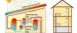
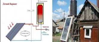
- At least a rough plan for the future regarding system improvement: what equipment and in what quantity are you going to connect in the future? Today, devices that allow the development of alternative heat sources are becoming increasingly accessible and efficient, so it is possible that soon you will want to retrofit your system with a heat pump or solar collector.
Based on these data, it is possible to calculate the comb parameters: diameter, length, number and dimensions of bends.
A two-story house is very high-status, cozy and beautiful. But such a house must be well heated. Heating diagram for a two-story house - an overview of the types of heating systems and installation tips.
Is it necessary to install a boiler safety group? Read on. Elements included in the system.
For instructions on assembling a mixing unit for heated floors, see here:. Useful tips from the experts.
What does the comb consist of?
Having decided on the adjustment method, having decided whether a three-way valve or thermal heads will be used, the remaining elements of the comb are assembled.
- The collector itself is two parallel tubes (supply and return) with outputs. One side of each comb is plugged. It can be purchased ready-made, but its cost is the main cost of the mixing unit (we are talking about thousands of rubles). It is much cheaper to assemble a comb from a series of tees, which have an internal thread on one side and an external thread on the other. The circuit tubes are connected to the side outlets (via fittings - crimp or solder).
- Manometer that controls pressure.
- A burst valve that will operate if the pressure is exceeded.
- Servo drives for each circuit are especially important when the length of the circuits is different (if you give free rein to the laws of physics, the temperature in them will be significantly different). Thermostats equalize pressure and temperature.
Manufacturing methods
Before you start making a homemade collector, you need to select the material and prepare the necessary equipment. For example, to make a steel model you will need a welding machine. But don’t rush to choose polypropylene. In order to connect polypropylene parts, you will need a special device that is used to weld such pipes. Sometimes it is easier to get an ordinary welding machine than for plastic.
Calculation and distribution of contours
From the very beginning, you need to understand how many heating circuits you will need. It is necessary to take into account each existing heating device, so you will have to evaluate each room according to the list below.
To avoid forgetting anything, use the following list:
- the presence of a “warm floor” system;
- rooms that should have a higher or lower temperature compared to other rooms;
- floor heating;
- heating of each wing.
The rules for manufacturing a heating collector are as follows: the distance between the taps is 10-15 mm, the distance between the supply and return collectors is 25-30 cm.
The diameter of the pipes should be 12.7 mm. The collector itself is made with a diameter of 25.4-38.1 mm, depending on which boiler is installed.
Made from polypropylene
To make a polypropylene manifold assembly with your own hands, you will have to use leftover pipes and fittings.
You will need:
- pipe with a diameter of 32 mm;
- tees 32/32/16 mm.
A tee must be installed on one side. An air vent must be connected to it at the top, and a drain tap at the bottom. On the other side, a valve and pipe are attached. The pipe can be supply or outlet, depending on the purpose of the collector. The supply pipe goes to the boiler.
The remaining outlet with a diameter of 16 mm must be equipped with a valve or flow meter, depending on which collector is for water supply or outlet. At this point the work is completed, and all that remains is to secure the resulting collector systems to the wall using brackets.
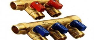
Assembly of brass fittings
If a ready-made brass manifold is quite expensive, then you can spend much less money on a homemade one. To build such a structure you will need tees and fittings. They are connected to each other using linen tow or a liquid fixative as a cushioning material. The parts must be connected according to the assembly diagram. An example can be seen in the picture below.
After the collector is assembled, it must be tested. It is difficult to make the connection correctly, so the likelihood of leaks is high.
From a profile pipe
Making a collector from pipes with different cross-sections is the most difficult, since it will require welding work. This model can be called the most “sophisticated”. It is suitable for heating large areas and can have many pipe connections. Often such samples are equipped with a hydraulic arrow.
The following samples will be needed:
- profile pipe 8x8 cm or 10x10 cm;
- round pipe.
The calculation of the pipe cross-section is performed in special programs. It is necessary to set the required heating thermal power, water speed, temperature difference between supply and return.
In this case, you will need to build a circuit, taking into account the number of circuits. Remember that the distance between wiring should be about 15 cm, and between collectors - at least 20 cm. A typical diagram looks like this.
Next, you need to mark a pipe with a rectangular cross-section according to the diagram, and then make holes for wiring using a gas cutter. Weld pre-prepared small parts of threaded pipes to the holes. The block is ready, all that remains is to weld the brackets to it, prepare it and paint it.
How it works
In short, such a comb is a distribution device for water that enters the apartment for heating. In fact, this is a rather complicated device.
Let's list its components:
- Two manifolds made of brass, equipped with adapters for incoming and outgoing pipes.
- Flow meters are installed on the incoming pipes.
- Thermal valves are installed on the outgoing pipes (as soon as the water cools to a certain temperature, they open and the water drains).
- Faucet with remote temperature sensor.
- Air bleeder.
- A special check valve that prevents coolant from flowing in the opposite direction.
- Drain tap.
- Return valve.
- Circulation pump.
The service life of this device is more than two decades. There are various options for combs for heated floors. You can connect a different number of thermal circuits to them. Typically, we are talking about a quantity from 2 to 16 pipes.
This device allows you to regulate the amount of water and the degree of heating of the coolant that enters the heated floor. Also, it is possible to adapt to different weather. After all, in cold weather you need a high degree of heating, but in other weather you may need a small degree of it.
This system allows you to use the same coolant for both apartment heating and underfloor heating. At the same time, uneven heating of the apartment floor can be avoided.
Boiler repair
In case of leakage, we repair fire tube boilers in the following sequence:
- We study the documentation and diagrams of the device.
- We search for the problem area and localize it.
- We clean the surface near the crack to bare metal to a width of 15-20 mm.
- We carry out welding work at ambient temperatures above +5C. We use electrodes with a thickness of 2.5 mm or 3 mm. We weld the seam from the side of the drum 2-4 mm larger than from the pipe. The welding direction is from the middle of the crack to the edges using two welding machines simultaneously.
- We clean the seam until it shines and look at its quality. If necessary, we eliminate deficiencies: uncooked areas and shells.
- We test the boiler.
Fire-tube water-heating boilers are used in boiler houses, for heating private households, in industry and other areas.
Sometimes in the construction of fire-tube boilers, due to improper operation, it becomes necessary to replace the damaged section. For these purposes, the gas-flame method is used. In this case, the dimensions of the damaged part must be at least 200 mm or the diameter of the pipe. First, they localize the area, then cut it out with a grinder until the thickness and properties of the metal are preserved, after which they clean and weld a patch made of steel of the same composition.
Fire-tube water heating boilers are used in boiler houses, for heating private households, in industry and other areas. This is due to their high heating efficiency and economical fuel consumption, reliability and ease of operation. The design of fire tube boilers is relatively simple, so they can be easily repaired even independently without the involvement of specialists.
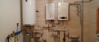
Installation nuances
The technology for attaching the collector to the wall is quite simple: the TC and radial distribution comb are suspended on mounting brackets, the loops are connected with Eurocone fittings. Pipes going to the top of the collector (usually the “return”) are passed under the bottom.
Advice. No one is forcing you to mount the distributor on brackets. If necessary, the tubes can be spread apart and mounted separately on the wall. The collector box is used in residential areas; when installing the collector in the boiler room, the cabinet is not needed.
Let's briefly list the main points:
- The size of the comb is selected according to the diameter of the pipes used in the heating loops - Ø16 or Ø20 mm. Accordingly, we take a ¾ or 1 inch distributor. The material of the product does not matter; in terms of price/quality ratio, stainless steel wins.
- If the number of comb outlets exceeds 12, assemble a collector assembly of 2 sections. When installing accessories, winding materials are not used, since the parts are equipped with rubber seals.
- A heavier common house collector is suspended on hooks, reinforced brackets, or installed on the floor. Pumps, pipes and other piping elements must not load the distributor with their own weight.
- The hottest coolant receives an indirect heating boiler. The coil and circulation pump of the water heater are connected to the comb directly, usually from the end.
- The radiator heating and TP branches are connected to the manifold through mixing units with three-way valves. A separate pump is installed on each line, selected for pressure and performance.