Autonomous heating systems can be built in different ways. One of the most popular types of heating systems in the home is the liquid-cooled design. Usually, water with special additives is used as it.
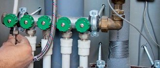
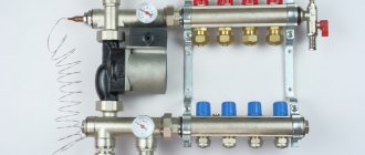
Heating distribution manifold
Such a system may have several heating circuits, for example, heating through radiators and through heated floors. In order for the water to be distributed evenly in such a system, a distribution heating manifold is needed.
Advantages
The collector method has its fans both among professionals and among ordinary people.
This is due to the positive features that this heating method guarantees.
- Heat is distributed evenly. A priori, it is assumed that the temperature entering the pipes from the collector does not drop. In this regard, uniform heating and temperature maintenance is achieved in all devices connected to the system. At the same time, there is always the opportunity to lower the temperature if necessary.
- Possibility of customization. If desired, you can not only regulate the temperature, but also completely turn off any of the branches. For example, if heating is not needed in one of the rooms, you can simply turn off the radiator, thereby preventing idle heat release. This is especially convenient if you live in a large house, for example, a 3-story mansion, and do not always use all the rooms. Adjustment is carried out from the manifold cabinet.
- Easy to repair. If any part of the system breaks, you do not have to turn off the entire system (we are not talking about the breakdown of the collector itself). It will be enough to shut off the heat supply to the damaged branch.
- Aesthetic appeal. By connecting the collector, you get the opportunity to place the pipes anywhere, not just above the radiator. Many take advantage of this circumstance and make the pipes hidden, hiding them under the baseboard or behind a false wall.
Control valves
VALTEC floor modules provide hydraulic balancing of the heating system at the level of risers and floor consumers. Units of the GPR and GPA series additionally allow you to automatically maintain the pressure difference at the inlet and outlet of the apartment heating system, linking the operation of the unit with other elements of the building system.
The possibility of balancing is achieved thanks to the inclusion of the following devices in the floor units of their VALTEC range of control valves:
1. Balancing valve VT.054 2. Automatic differential pressure regulator VT.040 3. Straight-through bypass with bypass valve and thermometer VT.0667T 4. Adjusting valve VT.020
The units are also equipped with fittings for input, consumer and service groups.
VALTEC floor units are supplied assembled (on request, delivery for on-site assembly is possible), with right or left connection to risers already tested at 15 bar pressure. Assembly and crimping of units is carried out in the factory.
VALTEC offers the widest range of standard floor units, and if your project requires a special configuration, the company’s design department specialists will develop an individual solution for you.
Album “Storey and apartment manifold units of heating systems for apartment buildings” (PDF, 75 MB)
Two ways to increase the diameter of distribution pipes
The first method is suitable for boilers with built-in pumps. For such boilers, a thermo-hydro distributor is made (popularly known as a water gun). A boiler and two or three heating circuits and hot water supply are connected to the hydraulic arrow. In this case, each heat consumption circuit is equipped with its own circulation pump.
Many also take the simple route and connect a small circuit of radiators and warm water floors to such a boiler. This works if you immediately switch from the boiler from ¾ to 1 inch and then connect everything with a pipe, for example, PPR with a diameter of 32.
But for many, work and construction are not limited to such small volumes. That is why it is not always reasonable to connect large houses or public buildings only to a hydraulic arrow. The arrow will turn out to be simply huge and the entire boiler room will be in pipes.
To avoid this, a simple manifold for distributing the coolant was first invented, and then a coplanar distribution manifold was made from it. That is, two independent collectors were combined into one and its coplanarity was obtained.
The coplanar distribution manifold in one fell swoop solved the problem of the number and size of connections for boilers and heating circuits, the problem of piling up pipes was solved, and it became very quick and easy to monitor, maintain and repair boiler equipment.
But as usual, the lack of information has led to the fact that we seem to know something about distribution manifolds, but we don’t use them, relying on chance. But it doesn’t carry through and the heating system constantly asks for coolant. There is no heat and all attempts to suck the heat out of a narrowed pipe lead to a waste of a lot of time, nerves and money.
When it’s just at the stage of conversation with the craftsmen before installing the system, it is necessary to voice the desire to manufacture and connect everything through the switch and the distribution manifold. Together, these two devices work even better. But here we may encounter ignorance. And this ignorance, in turn, can persuade you not to do this and put everything on one pipe.
Making a hydraulic arrow with your own hands is not difficult. We take a piece of pipe three diameters larger than the diameter of the boiler connection and weld curved plugs to the ends of the pipe. We weld threads into the plugs for draining and venting air. And we cut threads into the body of the pipe to connect boilers and heating circuits. We paint and the arrow is ready.
Purchasing and making a distribution manifold with your own hands is a little more complicated. Factory analogues often do not meet our conditions in terms of the number of connected circuits and their sizes.
Thus, it can be difficult or even impossible to select a factory distributor for your specific conditions, since the size of the manifold and the size of the manifold pipes are limited by the model range.
This is why you will either have to ditch the factory manifold or use two or more manifolds. In this case, it will be necessary to take into account the cost of two collectors, their installation and the cost of additional materials.
If you have a small house, then it is quite possible that a factory manifold will suit you. But most often this does not happen, and many people do not know what to do about it. Having suffered and suffered, they hire a plumber who does everything directly from the boiler. And then they complain that there is no heat.
That is why we must not forget that there are at least two ways out of any situation. And the second way out of this situation, if it is impossible to use a factory manifold, is to make a distribution manifold with your own hands.
That is why it is necessary to understand that without a collector, a system of more than three circuits will work incorrectly and be jammed. Otherwise, you may not read further and connect everything to one pipe and waste time and money to fix a broken system.
The main problem of heating systems
The main problem with heating systems is starvation. This is because several heating circuits are connected to one pipe of boiler connection diameter, and this is often a pipe with a diameter of 25 mm. Thus, the result is a clamped system with a lack of coolant specifically for the heating circuits. As a result, we end up with starvation of the heating system.
The coolant in heating systems is precisely the medium that absorbs heat (heat capacity of the coolant) and this heat in the coolant is transported through a pipeline system from the heat source to the heat consumer. Simply put, the heat accumulated in the coolant, by heating it to the boiler, is transported to radiators or other heat consumers through pipes.
That is why the amount of coolant in our case plays a key role. And if there is not enough coolant, therefore, there is no required amount of heat. That's why the heating system is starving.
Some people begin to install additional pumps, control valves, and so on, without understanding the unchanged truth: the amount of heat is proportional to the amount of coolant. And how can you remove heat if there is simply not enough of it? No one knows. Therefore, a very important point in heat distribution is the correct calculation of the boiler room, the number of boilers, the number of heating circuits and the diameters of the pipes with which all this will be connected.
Let's look at the example of a small house of 100-150 square meters. Often in such houses the main boiler is a gas wall-mounted boiler. How to choose the diameter of the pipes for connecting the heating circuits if the wall-mounted boiler has a ¾-inch connection.
In this case, it is necessary to connect two heating circuits and one indirect heating boiler circuit with connection diameters of 1 inch. Here it is clear even to a schoolchild that the diameter of our consumers relative to the diameter of the boiler is several times greater. That is why many people connect two or three heating circuits to the boiler with a pipe with a diameter of 25 ppr. Thus, there is not enough coolant and heat, and people begin to complain that the boiler is bad, the systems are bad, the pipes are bad and the plumbing is not very good either.
From practice, I noticed that there are no bad boilers, pipes, systems and plumbers. It’s just that at this stage, not everyone may have a proven production technology or lack the latest and up-to-date information. That's why I often recommend that HVAC clients keep abreast of developments . This helps to clearly set goals for your master about what you want. At the same time, keep track of all the reactions and previous works of the master. Today, taking your word for it is very little and expensive, because there are many words, but few deeds.
Therefore, let's talk about the matter and try to briefly and clearly solve the problem of lack of heat in heating systems. As you already understand, the main heating problem is the lack of coolant and this is often caused by the narrowing of distribution pipelines from heat sources to consumers .
Therefore, in order to increase the amount of coolant and heat, it is necessary to increase the diameter of the distribution pipes from the heat sources.
Types of collectors
Collector installations, which are used during the design of circulation-type heating systems, come in 3 types. Depending on the purpose, they can be radiator, solar and equipped with a hydraulic arrow. Their sizes are determined by the area of the heated room.
In this video you will become familiar with the concept of a distributor comb:
Radiator heating
Regardless of the type of heating system, the project always contains radiators, so collectors are a fairly popular type of device. You can connect them in different ways. The radiator system can be made in the following options:
- top battery connection;
- introduction diagonally;
- connection to the bottom input;
- side connection.
The most common is the bottom connection option. This layout allows you to hide the pipes under the floor or baseboard surface. Also, the greatest efficiency of the lower connection is confirmed by calculations.
When connecting the radiator from below, you can hide the work under the floor or baseboard
The collector is installed on each floor of a private house. It is installed in the center of the contour, masking it in some cabinet or special niche. The installation site must be located so that pipes of the same length are supplied to all radiators. If this cannot be done, then a circulation pump must be installed on each outlet.
Warm floors are installed from copper or polyethylene pipes. They are connected using one-piece fittings. For each ring, a separate shut-off valve is provided, which allows you to regulate the amount of coolant supplied, as well as turn off a separate section of the network. Such a heating scheme must always be equipped with a circulation pump. It is installed near the collector on a pipe with a return water supply.
The number of pipes depends on the number of rooms that are connected to the comb, as well as on the number of pins on the device. There may be several groups. It all depends on the length of the contours. There are approximately 120 meters of pipe per group.
Hydraulic boom
A device with a hydraulic arrow is installed when installing powerful heating systems that are necessary to heat a large area. On one side, the device is connected to the circuit from the boiler, and on the other, to heating with radiators or heated floors. The presence of such a device solves several problems simultaneously:
- Allows you to avoid large temperature differences in the system, which allows you to extend the life of the components.
- Saves fuel and electricity. This is achieved by adding secondary circulating water.
- If the need arises, you can replenish the missing amount of water in the secondary circuit.
The presence of a hydraulic arrow allows you to save fuel and electricity
The device separates the hydraulic circuit coming from the boiler from the secondary circuit. This maintains a constant temperature.
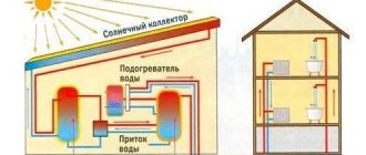
Solar installations
People choose such devices for installing an autonomous water supply system that does not have gasification. In this case, the amount of sunlight should be quite large.
The design of a solar installation is somewhat different from its traditional counterparts. Such devices are similar to a greenhouse that accumulates thermal energy from solar radiation.
The distributor is made in the form of a flat box, which is covered with a dark plate. This absorbent plate allows heat to be accumulated. The accumulated energy is completely transferred to some coolant.
Movable systems are also available on the market. They have drives that allow you to change the position of the plate in accordance with the movement of the Sun. This maximizes solar energy absorption. But the use of such installations is unprofitable due to their high cost. Most often they are used as an additional heating source.
Modifications of distribution combs
Today there are many types of collector devices designed for heating systems on the market. You can find conventional connecting links that do not have auxiliary shut-off valves. There are also complex blocks with many additional elements.
The simplest devices are made of brass and have inch holes. On the reverse side they have plugs that can be used to expand the system and add additional secondary devices.
Mechanisms with a more complex design have components that are equipped with ball valves. Shut-off valves are installed on each outlet element. More expensive devices may have:
- Flow meters. They are necessary to regulate the flow of coolant for each individual loop.
- Electronic valves. Their purpose is to maintain the required temperature.
- Thermal sensors.
- Valves for automatic removal of air from the system.
The number of circuits can vary from 2 to 10. It all depends on the consumers. Intermediate manifolds can be made of brass, stainless steel, polypropylene. Most often they choose polypropylene, as they are the cheapest.
Types of collectors, connection diagrams
With all the variety of design solutions for installing warm water floors, they are divided into two types: serial and parallel. The difference between them lies in the method of mixing cold and hot coolant flows in the heating system.
With a sequential mixing scheme, the entire mass of water from the circulation pump enters through the manifold directly into the heating circuit. The scheme allows maximum use of useful energy from the boiler.
Diagram of serial connection of a circuit with bypass
The diagram shows that the entire pump flow goes through the manifold into the heated floor circuit and is not shared anywhere. There can be several such circuits coming out of the manifold, and the success of their operation depends only on the performance of the circulation pump.
Such a mixer includes a bypass valve that regulates the addition of hot water. Typically thermostatic valves with thermal heads and an application sensor are used
Scheme for adjusting the temperature in the mixing unit with a bypass valve
For the bypass in this case, you need to use a pipe of the same size as for the main system. To ensure the pump operates when the circuits stop between the forward and return arms of the collector, it is necessary to install a second low-flow bypass.
This scheme ensures heat transfer in the circuit and, from the point of view of thermal engineering, is the most advanced.
By swapping the bypass and pump, you can get a typical parallel flow mixing scheme.
Typical circuit for parallel mixing of coolant
When the heating circuits are completely closed, the bypass valve allows the entire flow to pass through itself, allowing the pump to operate. Since the water circulates in a closed small loop, the load on the pump motor will be minimal and save energy. Complete closure of the circuits occurs when split systems are used when the floor overheats above the set temperature.
Thus, using a minimum number of components, it is possible to make the operation of a warm water floor system stable in all situations.
Feed and return manifold comb device
Combs are one of the main elements of the collector circuit; their main function is to distribute the coolant flow along the heating circuits. The element has a different design for lines of connected radiators and heated floors, the maximum number of involved circuits per collector does not exceed 12.
In relation to the diameters of the outlet fittings, the comb has a large cross-section (1.1 1/2 inches versus 3/4) and is connected to the main line through an end connection with elements of plumbing fittings. Typically, the pipeline is connected to the outlet fittings using compression fittings (Eurocones) - this method can be used to connect pipes made of cross-linked and heat-resistant polyethylene, metal-plastic, most often used in manifold heating systems. Combs are made of stainless steel, brass, plastic, some modifications are assembled from individual links.
Operating principle of the distributor
Most people don't know what a manifold is for in a heating system. This device evenly distributes several flows that come from main heating systems. The comb provides good circulation characteristics of the coolant. Each circuit connected to the collector is in no way dependent on the other.
Main elements of a water heating collector:
- Feeding comb. With its help, coolant is supplied to the heating system of the house.
- Reverse comb. Returns cold coolant to the boiler or other heating device.
Both elements create a collector group. The device is connected to several heating circuits at once. Shut-off valves can be provided for each terminal. With its help, the intra-circuit pressure is adjusted in each individual case, and one circuit is also disconnected for repairs without stopping the others.
The comb is designed to ensure good circulation performance of the coolant
To optimize all processes and increase system performance, the comb is used as an installation unit:
- heat meter;
- valves for removing air from the circuits;
- flow meter;
- valve for draining coolant.
The operating principle of the heating distribution unit is quite simple. The heated liquid enters under pressure into the manifold supply device. The heating comb has a larger diameter, due to which the speed of movement of the coolant becomes much lower. Water is distributed between all circuits under the same pressure.
The connecting sections have a cross-section smaller than the collector pipes. The device transfers the coolant to all offices to which radiators or a heated floor system are connected. Thanks to this, you can warm up every element of the system.
The main devices are attached to the comb
After the water reaches the radiator and releases a certain amount of thermal energy, it returns through the second pipe to the distribution block. Through it, the coolant is again sent to the heat generator.
This system is considered the most effective for private homes. But such a heating arrangement requires large investments when compared with the installation of standard heating.
Hydraulic boom and its function
This is a fairly simple device. It can be made from a piece of pipe with a cross-section three times larger than the boiler outlet pipe. It is necessary to weld curved plugs onto the ends of the segment. The plugs are then tapped with threaded holes. They will serve to vent air or drain water. We drill holes in the body of the pipe, in which we also cut threads. We will connect the boiler outlet pipe and heating circuits to them. The body of the hydraulic arrow must then be sanded and painted.
hydraulic arrow
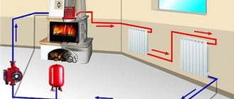
Operating principle of the heating system
The coolant, be it water or antifreeze, is heated by the boiler, the circulation pump forces it to move to the distribution manifold, or rather, to its fittings, to which the lines leading to heating devices are connected, most often radiators, sometimes heated floors.
Having passed through the heating circuits, the coolant returns through the return lines and, using an electric pump, is supplied to the boiler, where the heating cycle begins again.
In this case, the temperature of the coolant in the circuits is set using a thermostat, which is located on the inlet of the fitting of the supply part of the distribution manifold; each outlet is equipped with a flow meter that regulates the volume of supplied coolant.
The pressure in the lines is controlled by a thermostat, since as the temperature of the coolant changes, the pressure in the circuits changes.
It is worth noting that the pressure in a working system is also affected by air pockets; to eliminate them, the system is equipped with either Mayevsky taps or air vents; in an open heating system, air bubbles escape into the atmosphere through the tank.
What to pay attention to
Any solar installation is characterized by a rated power, which is indicated in kilowatts. This is the amount of energy that is generated when the sun is bright at its zenith. This means that the system's efficiency will decrease in the morning and evening. At night, most likely, it will be possible to use hot water only from the boiler, where water has accumulated throughout the day.
When choosing a collector model, pay attention to whether it can be used in winter. And what power should the system to which the collector is connected have?
The installation of collectors is usually carried out on the roof or on a frame, which is mounted separately.
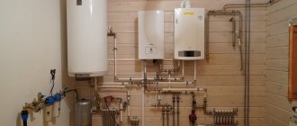
System installation
It is advisable to install a collector heating system during the pre-finishing period.
With a horizontal type of heating distribution, a special closed box is installed for the distribution manifold, pump and equipment for adjusting parameters.
In a building consisting of two floors, collectors with associated equipment are installed on all floors.
Each collector has a certain number of inlet and outlet openings, exactly as many as heating devices - radiators or heated floor coils.
In all rooms, separate branches are laid, combining several heating devices; with this connection, two radiators from the same room for the collector will represent a single heating device.
To organize a heated floor, a collector heating system with wiring in the floor is used. However, not only the installation of heated floors involves laying pipes from below.
Most often, a collector heating system involves placing heating lines under concrete; the height of the screed should vary from 5 cm to 8 cm. Only solid lines are placed in concrete, mostly metal-plastic pipes with a diameter of 1.6 cm. Such pipes are quite flexible, they can be easily lay under concrete.
It is worth remembering that before pouring concrete, a layer of thermal insulation is laid on the pipes and this is done in order to prevent contact between the concrete and the pipes.
The lines can be connected to the radiators either from above or from below, that is, the manifold wiring of the heating system can be top or bottom.
If you are not afraid of the additional costs associated with purchasing more pipe footage, then you can run the pipes along the edge of the ceiling and hide them in the ceiling plinth or hide them with a suspended ceiling.
To avoid damage, pipes are laid exclusively through the wall.
In a heating system, the formation of air bubbles and plugs is inevitable; to release them, special valves are installed on the distribution units, and Mayevsky taps are installed on the radiators.
Finally, I would like to say that, of course, you can assemble and install a collector heating system with your own hands; for this you need to take into account many factors and have a certain skill.
But if you doubt your capabilities, it is better to seek the help of professionals; this will protect you from damage to consumables, waste of nerves and will guarantee high-quality and timely commissioning of the entire heating system.
Positive and negative aspects of the collector circuit
When planning the installation of heating with collector wiring, you should carefully study the technical side of the issue and determine all the positive and negative qualities of this system. Taking these qualities into account when building a house, you will be able to achieve its greatest energy efficiency.
- direct control of each individual radiator of the system;
- a differentiated approach to heat distribution in each room, which makes it possible to effectively maintain the required temperature throughout the house, while saving money;
- ease of operation, the ability to access each component of the system without interfering with the operation of the others;
- aesthetic component, which consists in the possibility of installing the pipeline and auxiliary components of the system in the wall or floor;
- high payback associated with efficient consumption of energy resources.
Negative qualities: high costs at the initial stage of design and installation associated with the need to use pipes and additional components;
As you can see, there are not many disadvantages, they are not significant in comparison with the advantages of the system. Therefore, a collector heating system is rightfully considered the best solution today.
Types of collectors
Today the market offers a wide variety of collector systems. The simplest designs are devoid of adjustment and other equipment - this allows the buyer (master) to decide for himself what equipment he will install in the future. There are also ready-to-use collector blocks, “stuffed” with all kinds of elements (ball valves, flow meters, temperature sensors, etc.). It's convenient, but expensive. In addition, it may happen that some components will not be in demand at all. Why overpay?
Polypropylene Tebo with 3 outlets, with taps, 25x20 mm.
Heating distribution manifolds are available with bottom, top or side connections. The first connection method is the most popular, as it allows you to hide the wiring as much as possible and improve the aesthetics of the room. Ideally, the collector is placed in a niche or a special cabinet, but in such a way that access to it is free.
In large houses with a powerful and highly ramified heating system, the “combs” are supplemented with a hydraulic arrow. Essentially, it is a vertical pipe with end caps designed to equalize operating pressure parameters and prevent water hammer. On one side, the arrow is connected to the heating circuit, and on the other, to the boiler circuit. With this scheme, it is recommended to equip each circuit with its own circulation pump, otherwise such an innovation is unlikely to be justified.
Nickel plated Valtec, 3 pins.
Heating distribution manifolds are made from the following materials:
- brass;
- stainless steel;
- polymer.
Brass “combs” are perhaps the most optimal in terms of price/quality ratio. Products made from stainless steel are the most environmentally friendly and durable, but also the most expensive. Polymer analogues are relatively inexpensive, but in all respects they are inferior to the above-mentioned counterparts.
Uponor brass manifold, 2 outlets.
Uponor brass, 2 outlets, return.
Collector design and principle of operation
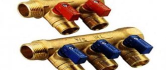
The direct function of a collector in a water supply system is to distribute one water flow into several flows of equal pressure.
Combs with two, three and four outlets are available. If more branches are needed, the distributors are connected to each other. In this way, a water supply collector is assembled for the required number of outlets.
The collector is connected directly to the riser. On two opposite sides of the device there is a threaded connection (internal thread on one side, external thread on the other) for connecting to the main line and connecting the combs to each other.
A plug or an additional plumbing device, for example, a membrane water hammer absorber, is installed at the free end of the collector.
The diameter of the inlet hole is 20-40% larger than the outlet hole. For example, on a standard manifold for installing water supply in an apartment, the diameter of the inlet hole is 3/4 inch, the outlet hole is 1/2 inch.
1. Manifold with valves.2. Manifold with ball valves.
Both ball valves and valves can be installed at the outlet openings, allowing not only to open and close the water flow, but also to regulate the power of the flow in this area.
Types of heating collectors
There are three types of collector installations that are used when designing closed systems with forced circulation. Their main difference is in the purpose of the design.
There is also such a thing as an accelerating manifold. This is a vertical riser that goes after the boiler. It is used only in single-pipe systems with natural coolant flow. Here the heated coolant picks up the necessary speed for gravitational current through the pipes of the circuit to the radiators.
Radiator
A thermal collector for heating a house is in demand in any system with radiators. Depending on the design features of the building, collectors are connected in different ways. You can use diagonal, side, top and bottom connections. Most often, the bottom connection is chosen because the circuit can be laid in a screed.
Radiator collectors are installed on each floor in a special niche or cabinet
It is important that branches of approximately the same length go to all devices from the comb. If the length differs significantly, then each outlet has its own circulation pump
Hydroarrow
When designing complex branched heating systems in large houses, a thermo-hydraulic distributor is installed, which is also called a hydraulic switch. On one side, the heating equipment circuit is connected to the device, and on the other, heated floors or heating devices are connected.
Hydrostrelka solves the following problems:
there are no sudden changes in coolant temperature that shorten the service life of the system; the hydraulic arrow ensures secondary circulation of liquid and its addition from the return line to maintain a constant volume of water in the boiler (this is important for saving electricity and energy resources); if there is a shortage of coolant in the secondary circuit, the comb compensates for the shortage.
A hydraulic head separates the boiler circuit from the secondary circuit, ensuring temperature balance. But for optimal operation of the system with a hydraulic arrow, each circuit must have its own pumping equipment.
Solar collectors
This device is used to organize autonomous heating in areas without gasification, but with sufficient solar radiation. Essentially, these are greenhouses for collecting solar energy. The coolant circulates due to convection and fans. A black absorbent plate is installed to accumulate heat.
Water or liquid is used as a coolant. However, this system cannot be used as the main source of thermal energy even in the southern regions. It is usually used as additional heating in combination with a solid fuel boiler.
Let's move on to making the distribution manifold with our own hands
To properly make a collector with your own hands, it is necessary to determine the exact number of heating circuits at the design stage of your system. It is necessary to determine boilers, indirect heating boilers that will be installed immediately and boilers that will be installed in the future. These can also be solar collector systems, heat pumps, and so on.
After the equipment, we determine the number of heating circuits - these can be radiator heating systems, heated floors, convectors, heated walls, and so on.
After an exact determination, we will have the exact number of circuits ( a circuit is a pair of connections to the manifold, consisting of two supply and return pipes ). We will also have accurate models of equipment and heating circuits with pipe connection sizes.
It is also necessary to decide on additional equipment - these are expansion tanks, automatic make-up valves, drain and fill taps for the system, pressure gauges, thermometers and safety groups.
Now we count the number of circuits, determine the direction from which these circuits will come to the collector, that is, from above, below or from the side. From practice, solid fuel boilers and indirect heating boilers are usually cut into the ends of the collector. Wall-mounted electric and gas boilers are usually cut into the top and also into the end, if they have their own circulation pumps and there is a need to connect through a hydraulic arrow.
In this case, the heating circuits cut into the top or bottom of the collector, since the collector is usually located in the basement or on the first floor.
Advantages of a collector heating system
The main advantages that a heating comb provides are the ease of operation and control of the system.
Additional advantages are as follows:
- Thanks to the installation of a manifold, each component element of the heating circuit can be controlled centrally and independently. You can set different temperatures in any room, turn off individual heating devices or entire groups.
- Each line laid from the collector supplies coolant to one battery or group of devices, so wiring can be done from pipes of a small cross-section. Pipelines are often laid in the floor screed, trying to reduce the distance between the heating device and the comb to a minimum.
- If necessary, the collector circuit allows you to combine several circuits with different coolant parameters. In this case, a hydraulic arrow is installed, which is a type of collector and is a large cross-section pipe. It provides a connection between supply and return and regulates coolant flows.
Among the disadvantages are the following:
- greater consumption of thermal energy than with a series connection;
- when using radial wiring, there is an overconsumption of materials, and the network itself will spoil the interior;
- hidden laying of pipelines has many disadvantages;
- high hydraulic resistance when using small-section pipes forces the installation of circulation pumps;
- when creating several circuits, it is necessary to install the same number of circulation pumps, which increases the cost of organizing the system;
- Due to the mandatory use of pumping equipment, the heating system is energy-dependent and therefore not suitable for populated areas with interruptions in power supply.
Making a drawing
Now we take a piece of squared paper or graph paper and draw on it a diagram of our distribution manifold, which you will make with your own hands. In this case, we take the distance between the contours at our discretion. For example, the minimum is 100 mm, and a comfortable maximum is 200 mm. It is also necessary to determine the distance between the flow and return of heating circuits and boilers. Here, too, the minimum is 100 mm, and the maximum should be the same with the distances between the contours or much less in order to visually highlight the contours.
But if you want to install factory pumping stations or mixing modules, then determine their models and take the exact dimensions, which you transfer to the drawing.
Let's look at drawing a collector circuit using the most common six-circuit collector model. First we draw the supply and return manifold itself.
Next, we use the ends of the collector. This can be a floor-standing boiler or an indirect heating boiler. We immediately set the thread sizes.
Now we draw the contours of heating and other boilers. We immediately put down the dimensions between the contours and the dimensions of the connection threads. You can label these circuits and boiler connections so that you don’t forget or confuse anything.
Next, we place the threads of the additional equipment and set the dimensions. These are the threads for filling the system, draining the system, expansion tank, protection unit and thermometers in the front part of the manifold.
We check everything again and, if necessary, make adjustments, and transfer the drawing to another clean sheet. This will be the starting point for precise manufacturing of the distribution manifold with your own hands.
After drawing the final drawing of the collector, we calculate the required material and set approximate or exact prices. This is convenient to do in Excel.
After drawing up an estimate for the collector, we purchase the material, prepare the tools and begin manufacturing the collector.
Technical characteristics of VALTEC floor units
| Working pressure, MPa | Up to 1.3 |
| Test pressure, MPa | 1,5 |
| Working environment temperature, ºС | Up to +95 |
| Permissible ambient temperature, ºС | From +5 to +55 |
| Permissible relative ambient humidity, % | Up to 80 |
| Number of outlets on collectors, pcs. | 2–8 |
| Range of supported pressure drops (for GPR units), kPa | 20–60 |
| Range of supported pressure drops (for GPA units), kPa | 5–30, 25–60 |
| Maximum total coolant flow (with connection ¾"; 1"), m³/h | 1,7; 2,3 |
| Maximum thermal power of the unit at ΔT=20 °C (with connection ¾”; 1”), kW | 39,5; 54,5 |
| Diameter of nominal bore of the collector, mm | 40 |
| Connection to taps | 3/4″, “eurocone” |
| Maximum coolant flow for each outlet, m³/h | 0,95 |
| Maximum thermal power for each outlet at ΔT=20 °C, kW | 22 |
| Average total service life, years | 30 |
Technical data sheet (PDF, 1.25 MB)