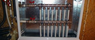
The elevator unit is specialized equipment located in the thermal distribution center. The main tasks of this device are: increasing the volume of heated water, reducing its pressure and t, as well as pumping. The operation of conventional elevators is adjusted by reducing or increasing the size of the component parts. There are also mechanically and electrically adjustable elevators.
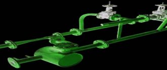
The functioning of the heating system schematically Source elevator66.ru
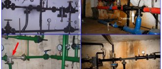
Heating system design
A thermal unit is a way to connect a home heating system to the main networks.
The structure of the heating unit in a typical Soviet-era apartment building includes: a mud trap, shut-off valves, control devices, the elevator itself, etc. The elevator unit is placed in a separate ITP room (individual heating point). There must certainly be shut-off valves in order to, if necessary, disconnect the intra-house system from the main heat supply. In order to avoid blockages and blockages in the system itself and in the devices of the internal house pipeline, it is necessary to isolate the dirt coming along with hot water from the main heating network; for this purpose, a mud trap is installed. The diameter of the mud trap is usually from 159 to 200 millimeters; all incoming dirt (solid particles, scale) collects and settles in it. The mud trap, in turn, needs timely and regular cleaning.
Control devices mean thermometers and pressure gauges that measure temperature and pressure in the elevator unit.
Design and principle of operation of a heating elevator
At the entry point of the heating network pipeline, usually in the basement, a node that connects the supply and return pipes catches your eye. This is an elevator - a mixing unit for heating a house. The elevator is manufactured in the form of a cast iron or steel structure equipped with three flanges. This is an ordinary heating elevator; its operating principle is based on the laws of physics. Inside the elevator there is a nozzle, a receiving chamber, a mixing neck and a diffuser. The receiving chamber is connected to the “return” using a flange.
Superheated water enters the elevator inlet and passes into the nozzle. Due to the narrowing of the nozzle, the flow speed increases and the pressure decreases (Bernoulli's law). Water from the return line is sucked into the area of low pressure and mixed in the mixing chamber of the elevator. The water reduces the temperature to the desired level and at the same time the pressure decreases. The elevator operates simultaneously as a circulation pump and mixer. This is briefly the principle of operation of an elevator in the heating system of a building or structure.
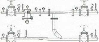
Thermal unit diagram
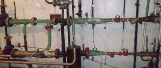
Adjustment of the coolant supply is carried out by the elevator heating units of the house. The elevator is the main element of the heating unit and needs piping. The control equipment is sensitive to contamination, so the piping includes dirt filters that are connected to the “supply” and “return”.
The elevator harness includes:
- mud filters;
- pressure gauges (inlet and outlet);
- temperature sensors (thermometers at the elevator inlet, outlet and return);
- valves (for preventive or emergency work).
This is the simplest circuit option for adjusting the temperature of the coolant, but it is often used as the basic device of a thermal unit. The basic elevator heating unit for any buildings and structures provides regulation of the temperature and pressure of the coolant in the circuit.
The advantages of using it for heating large objects, houses and high-rise buildings:
- reliability due to the simplicity of the design;
- low cost of installation and components;
- absolute energy independence;
- significant savings in coolant consumption up to 30%.
But while there are undeniable advantages of using an elevator for heating systems, the disadvantages of using this device should also be noted:
- the calculation is done individually for each system;
- a mandatory pressure drop is required in the heating system of the facility;
- if the elevator is unregulated, then it is impossible to change the parameters of the heating circuit.
Elevator with automatic adjustment
Currently, elevator designs have been created in which the nozzle cross-section can be changed using electronic adjustment. This elevator has a mechanism that moves the throttle needle. It changes the lumen of the nozzle and as a result the coolant flow changes. Changing the lumen changes the speed of water movement. As a result, the mixing ratio of hot water and water from the “return” changes, thereby achieving a change in the temperature of the coolant in the “supply”. Now it’s clear why water pressure is needed in a heating system.
The elevator regulates the flow and pressure of the coolant, and its pressure drives the flow in the heating circuit.
Control
We present the procedure for performing some operations related to the operation of the elevator.
Start heating
If the system is full, you just need to open the house valves and circulation will begin.
The instructions for starting a reset system are somewhat more complicated.
- The discharge on the return line opens and the discharge on the supply line closes.
- Slowly (to avoid water hammer) the upper house valve opens.
- After clean, air-free water flows into the discharge, it closes, after which the lower house valve opens.
Work without nozzle
When the return temperature is catastrophically low during the peak of cold weather, it is practiced to operate the elevator without a nozzle. The system receives coolant from the route, not the mixture. The suction is suppressed with a steel pancake.
Differential adjustment
If the return flow is too high and it is impossible to quickly replace the nozzle, adjusting the differential with a valve is practiced.
How to do it yourself?
- The supply pressure is measured, after which the pressure gauge is placed on the return line.
- The inlet valve on the return line closes completely and gradually opens with pressure control using a pressure gauge. If you simply close the valve, its cheeks may not completely move down the stem and will slide down later. The price of the wrong procedure is guaranteed defrosted access heating.
No more than 0.2 atmospheres of difference should be removed at a time.
The return temperature is re-measured a day later, when all values have stabilized. Date: September 25, 2022
Why do you need a thermal unit?
The heating point is located at the entrance of the heating main to the house. Its main purpose is to change the parameters of the coolant. To put it more clearly, the heating unit reduces the temperature and pressure of the coolant before it enters your radiator or convector. This is necessary not only so that you do not get burned from touching the heating device, but also to extend the service life of all heating system equipment
This is especially important if the heating inside the house is installed using polypropylene or metal-plastic pipes. There are regulated operating modes of thermal units:
These figures show the maximum and minimum temperature of the coolant in the heating main.
Also, according to modern requirements, a heat meter must be installed at each heating unit. Now let's move on to the design of thermal units.
Technical characteristics of standard models
Factory copies have 7 types of designs, differing in size, each of them has its own special number. To successfully select a good option and avoid problems during crimping, it is worth considering two parameters - the diameter of the mixing chamber and the nozzle.
With the second component the situation is simpler; it can be replaced if necessary, because the body is removable. Such actions are resorted to in 2 options:
- Wear of a part after a certain time (wear and tear due to abrasive particles).
- Changes in the mixing ratio, which is necessary to increase or decrease the temperature of the coolant.
I learned an interesting fact about the operation of the elevator unit: often in the technical specifications there is no point that introduces the buyer to the nozzle cross-section; the diameter is calculated separately. The main attention is focused on the mixing and injection chamber in order to accurately calculate the size for a specific heating system.
Determining the value of the thermal unit
An elevator is a non-volatile independent device that performs the functions of water-jet pumping equipment. The heating unit lowers the pressure and temperature of the coolant by mixing in cooled water from the heating system.
The equipment is capable of transmitting coolant heated to the highest possible temperatures, which is beneficial from an economic point of view. A ton of water heated to +150 C has much greater thermal energy than a ton of coolant with a temperature of only +90 C.
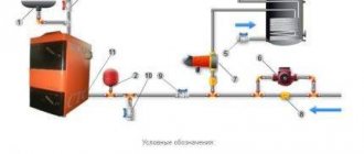
Operating principles and detailed diagram of the thermal unit
To understand how the equipment works, you need to understand its structure. The layout of the elevator heating unit is not complicated. The device is a metal tee with connecting flanges at the ends.
The design features are:
- the left nozzle is a nozzle tapered towards the end to the design diameter;
- Behind the nozzle there is a cylindrical mixing chamber;
- the lower pipe is needed to connect the water return circulation pipeline;
- the right pipe is a diffuser with expansion that transports hot coolant into the network.
Despite the simple design of the thermal unit elevator, the operating principle of the unit is much more complex:
- The coolant heated to a high temperature moves through the pipe into the nozzle, then under pressure the transportation speed increases, and the water quickly flows through the nozzle into the chamber. The effect of a water jet pump maintains a given intensity of coolant flow in the system.
- As water passes through the chamber, the pressure decreases and the stream passes through the diffuser, providing a vacuum in the mixing chamber. Then, under high pressure, the coolant moves the liquid returned from the heating line through the jumper. The pressure is created by the ejection effect due to the vacuum, which maintains the flow of the supplied coolant.
- In the mixing chamber, the temperature regime of the flows decreases to +95 C, this is the optimal indicator for transportation through the home heating system.
Understanding what a heating unit is in an apartment building, the principle of operation of an elevator and its capabilities, it is important to maintain the recommended pressure difference in the supply and return pipelines. The difference is necessary to overcome the hydraulic resistance of the network in the house and the device itself
The elevator unit of the heating system is integrated into the network as follows:
- the left pipe is connected to the supply line;
- lower – to pipes with reverse transportation;
- shut-off valves are mounted on both sides and are supplemented with a dirt filter to prevent clogging of the unit.
The entire circuit is equipped with pressure gauges, heat consumption meters, and thermometers. For better flow resistance, the jumper is cut into the return pipeline at an angle of 45 degrees.
Advantages and disadvantages of thermal units
A non-volatile heating elevator is inexpensive, does not need to be connected to a power supply, and works flawlessly with any type of coolant. These properties ensured the demand for equipment in houses with central heating, where a high degree of heating coolant is supplied.
Disadvantages of use:
- Maintaining the differential water pressure in the return and supply pipelines.
- Each line requires specific calculations and parameters of the heating unit. At the slightest change in liquid temperature, you will have to adjust the nozzle holes and install a new nozzle.
- There is no way to smoothly regulate the intensity and heating of the transported coolant.
Units with adjustable flow area by manual or electric drive of a gear transmission located in the antechamber are offered for sale. But in this case, the device loses its energy independence.
Main malfunctions of the elevator unit
Even such a simple device as an elevator unit may not work correctly. Malfunctions can be determined by analyzing pressure gauge readings at control points of the elevator unit:
- Malfunctions are often caused by pipelines becoming clogged with dirt and solid particles in the water. If there is a pressure drop in the heating system, which is significantly higher before the sump tank, then this malfunction is caused by a clogged sump tank located in the supply pipeline. Dirt is discharged through the drain channels of the mud collector, and the meshes and internal surfaces of the device are cleaned.
- If the pressure in the heating system fluctuates, then possible causes may be corrosion or clogged nozzle. If the nozzle is destroyed, the pressure in the heating expansion tank may exceed the permissible limit.
- It is possible that the pressure in the heating system increases, and the pressure gauges before and after the sump tank in the “return” show different values. In this case, you need to clean the return dirt trap. The drain taps on it are opened, the mesh is cleaned, and contaminants are removed from the inside.
- When the size of the nozzle changes due to corrosion, a vertical misalignment of the heating circuit occurs. The radiators below will be hot, but on the upper floors they will not be heated enough. Replacing the nozzle with a nozzle with a calculated diameter eliminates this problem.
Kinds
There are two types of these devices:
- Elevators that cannot be regulated.
- Elevators, the operation of which is controlled by an electric drive.
When installing any of them, it is very important to maintain tightness. This equipment is installed in a heating system that is already functioning
Therefore, before installation, it is recommended to study the location where the subsequent placement of this equipment is planned. It is recommended to entrust this type of work to specialists who are able to understand the scheme, as well as develop drawings and perform calculations.
Connection diagrams for the elevator unit of the heating system
The processes of heating water for hot water supply (DHW) and heating systems are in some way interconnected.
Due to the fact that the temperature of the water in the hot water supply under any conditions must be maintained within 60 - 65 degrees, at positive outside air temperatures, a hotter coolant than required may enter the elevator.
In this case, there is an excess heat consumption at the level of 5% - 13%. To avoid this phenomenon, three connection schemes for the elevator unit are used:
- with water flow regulator;
- with adjustable nozzle;
- with a regulating pump.
With water flow regulator
If this condition is met, it is possible to avoid floor-by-floor misadjustment, which occurs in single-pipe systems when the coolant flow rate decreases.
However, the “elevator + flow regulator” circuit is not able to maintain the temperature after this device at an acceptable level in case of deviations from the normal temperature curve.
With adjustable nozzle
The cross-sectional area of the nozzle outlet is controlled by the needle inserted into it. At the same time, the mixing coefficient increases and, accordingly, the temperature of the coolant after the elevator decreases.
The disadvantage of this scheme is that when a needle is inserted into the hole of the cone, the hydraulic resistance of the cone increases, as a result of which the coolant flow rate, and, accordingly, the amount of supplied heat, decreases.
Schematic diagram of an adjustable elevator unit
With control pump
The pump is mounted on the mixing line of the elevator unit or parallel to it. In addition to it, coolant flow and temperature regulators are installed. This solution is very effective because it allows:
- regulate the temperature of the coolant at any outside temperature, and not just at positive temperatures;
- maintain coolant circulation in the internal network when the external network is stopped.
The disadvantages of the scheme include high cost, complexity and increased operating costs due to the power supply to the pump.
Purpose of testing
The main must be checked for integrity and tightness; this is precisely why the system was developed; testing of pipes and components makes it possible to timely detect gaps in threaded pipes and assess the tightness of heating or hot water supply connections.
Without such actions, one cannot count on a minimal threat from leaks and flooding of premises. Before putting the highway into operation, an inspection is carried out; this process is mandatory for implementation.
DHW from an individual heating point
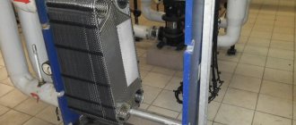
The simplest and most common is the scheme with single-stage parallel connection of hot water heaters (Fig. 10). They are connected to the same heating network as the heating systems of buildings. Water from the external water supply network is supplied to the DHW heater. In it, it is heated by network water supplied from a heat source.
Rice. 10. Scheme with dependent connection of the heating system to an external network and single-stage parallel connection of the DHW heat exchanger
The cooled network water returns to the heat source. After the hot water heater, the heated tap water enters the domestic hot water system. If the devices in this system are closed (for example, at night), then hot water is again supplied through the circulation pipeline to the DHW heat exchanger.
In addition, a two-stage hot water heating system is used. In it, in winter, cold tap water is first heated in the first stage heat exchanger (from 5 to 30˚C) with coolant from the return pipeline of the heating system, and then water from the supply pipeline of the external network is used to finally heat the water to the required temperature (60˚C) . The idea is to use waste heat from the return line from the heating system for heating. At the same time, the consumption of network water for heating water in the hot water supply is reduced. In summer, heating occurs according to a single-stage scheme.
Rice. 11. Diagram of an individual heating point with an independent connection of the heating system to the heating network and a parallel connection of the hot water supply system
For multi-storey high-rise (more than 20 floors) housing construction, schemes with independent connection of the heating system to the heating network and parallel connection of hot water supply are mainly used (Fig. 11). This solution allows you to divide the heating and hot water systems of the building into several independent hydraulic zones, when one IHP is located in the basement and ensures the operation of the lower part of the building, for example, from the 1st to the 12th floor, and on the technical floor of the building there is exactly the same heating unit for the 13th – 24 floors. In this case, heating and domestic hot water are easier to regulate in case of changes in the heat load, and also have less inertia in terms of hydraulic mode and balancing.
Operating principle of central heating
The general scheme is quite simple: a boiler house or thermal power plant heats water, supplies it to the main heat-conducting pipes, and then to heating points - residential buildings, institutions, and so on. As the water moves through the pipes, it cools somewhat and at the final destination its temperature is lower. To compensate for the cooling, the boiler room heats the water to a higher value. The amount of heating depends on the outside temperature and the temperature schedule.
For example, with a schedule of 130/70 at an outside temperature of 0 C, the parameter of the water supplied to the main line is 76 degrees. And at -22 C – no less than 115. The latter is well within the framework of physical laws, since the pipes are a closed vessel, and the coolant moves under pressure.
Obviously, such overheated water cannot be supplied to the system, since an overheating effect occurs. At the same time, the materials of pipelines and radiators wear out greatly, the surface of the batteries overheats to the point of risk of burns, and plastic pipes, in principle, are not designed for coolant temperatures above 90 degrees.
For normal heating, several more conditions must be met.
- Firstly, the pressure and speed of water movement. If it is small, then the nearest apartments are supplied with overheated water, and the distant ones, especially the corner ones, are supplied with too cold water, as a result of which the house is heated unevenly.
- Secondly, for proper heating, a certain volume of coolant is required. The heating unit receives about 5–6 cubic meters from the main, while the system requires 12–13.
It is to solve all of the above issues that a heating elevator is used. The photo shows a sample.
Operating principle of the elevator unit
The mixing elevator serves as a device for cooling superheated water obtained from the heating network to a standard temperature before feeding it into the intra-house heating system. The principle of its reduction is to mix water at elevated temperatures from the supply pipeline and cooled water from the return pipeline.
The elevator consists of several main parts. This is a suction manifold (input from the supply), a nozzle (throttle), a mixing chamber (the middle part of the elevator, where two flows are mixed and the pressure is equalized), a receiving chamber (mixture from the return), and a diffuser (exit from the elevator directly into the network with established pressure ).
The nozzle is a narrowing device located in the steel body of the elevator device. From it, hot water at high speed and with reduced pressure enters the mixing chamber, where water from the heating network and the return pipeline are mixed by suction. In other words, hot water from the main heating network enters the elevator, in which it passes through a constriction nozzle at high speed and at reduced pressure, mixes with water from the return pipeline, and then, at a lower temperature, moves into the internal pipeline. You can see what the nozzle of a mechanical elevator directly looks like in the photo below.
In modern modifications of the elevator, the technology for controlling changes in the nozzle cross-section occurs automatically using electronics. In such a system, the mixing ratio of hot and chilled water varies, which reduces the cost of the heating system. These are so-called weather-dependent or adjustable elevators, and I wrote about this in.
This structure of the elevator has an actuator to ensure its stable operation, consisting of a direction device and a throttle needle, which is driven by a toothed roller. The action of the throttle needle regulates the coolant flow.
How to serve
The operation of the elevator is based on the action of physical laws, therefore its design does not provide for any moving or rotating parts. Even in more complex designs with a changing nozzle size, a special needle moves, increasing or decreasing the passage for the coolant (based on the principle of a spray gun), which does not have a high movement speed. Therefore, all maintenance of the device consists of timely cleaning of dirt, removing dirt that gradually accumulates due to the low quality of the coolant. Nozzles are subject to periodic replacement; they are subject to stress when exposed to a flow of hot water and are the first to fail. The diameter and condition of the nozzle are checked annually, replacement is carried out when the need arises - severe wear of the part, excessive increase or decrease in throughput. It is also necessary to monitor the tightness of flange connections and change gaskets and seals in a timely manner.
The role of the elevator unit
Heating of domestic apartment buildings is carried out through a centralized heating system. For this purpose, small thermal power plants and boiler houses are being built in small and large cities. Each of these objects produces heat for several houses or neighborhoods. The disadvantage of such a system is significant heat loss.
The principle of operation of the node
The building boundary is the outer walls and the top surface of the highest ceiling, the basement in basement buildings, or the ground level in buildings without basements. In the case of compact buildings, the boundary between individual objects is the contact plane of the top wall, and if there is a joint between two walls, the boundary between buildings passes through the center.
Building installation boundaries, depending on the type of installation, for example, fittings, inspection hatches, shut-off valves for water, gas, heating, etc. Building equipment includes all installations built into a permanent building, such as sanitary, electrical, alarm, computer, telecommunications, fire protection and general building equipment such as built-in furniture.
If the coolant path is too long, it is impossible to regulate the temperature of the transported liquid. For this reason, every home must be equipped with an elevator unit. This will solve many problems: it will significantly reduce heat consumption, and prevent accidents that may occur as a result of power failure or equipment failure.
This issue becomes especially relevant in the autumn and spring periods of the year. The coolant is heated in accordance with established standards, but its temperature depends on the outside air temperature.
Thus, the nearest houses, compared to those located further away, receive hotter coolant. It is for this reason that the elevator unit of the central heating system is so necessary. It will dilute the overheated coolant with cold water and thereby compensate for heat loss.
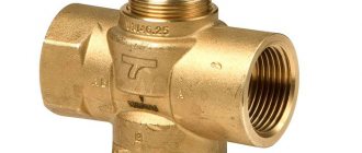
Three way valve
If it is necessary to divide the coolant flow between two consumers, a three-way heating valve is used, which can operate in two modes:
- constant mode;
- variable hydraulic mode.
A three-way valve is installed in those places in the heating circuit where it may be necessary to divide or completely shut off the flow of water. The tap material is steel, cast iron or brass. Inside the faucet there is a shut-off device, which can be ball, cylindrical or conical. The tap resembles a tee and, depending on the connection, a three-way valve on a heating system can work as a mixer. Mixing proportions can be varied within wide limits.
The ball valve is mainly used for:
- adjusting the temperature of heated floors;
- adjusting battery temperature;
- distribution of coolant in two directions.
There are two types of three-way valves - shut-off and control valves. In principle, they are almost equivalent, but with three-way shut-off valves it is more difficult to regulate the temperature smoothly.
- How to fill water into an open and closed heating system?
- Popular floor-standing gas boiler made in Russia
- How to properly bleed air from a heating radiator?
- Expansion tank for closed heating: device and principle of operation
- Gas double-circuit wall-mounted boiler Navien: error codes for malfunctions
Recommended reading
Expansion membrane tank of a heating system: device and functions Heating thermostat - operating principle of different types Bypass in a heating system - what is it and why is it needed? How to accurately choose an expansion tank for heating?
2016–2017 — Leading heating portal. All rights reserved and protected by law
Copying site materials is prohibited. Any copyright infringement will result in legal liability. Contacts
Design
- housings with a fixed elbow and a diffuser element with a mixer tank;
- cone-shaped nozzles that conduct the flow of water;
- all-consuming grid;
- integrated head on inlet and outlet pipes.
Equipment design
1 – knee; 2 – suction mesh; 3 – shell; 4 – nozzle; 5 – diffuser; 6 – connecting head GMN-80; 7 – connecting head GMN-70
The efficiency of a standard G-600 hydraulic elevator does not exceed 30%, however, this is enough to cope with many tasks, which this unit solves as quickly as possible.