Due to high pressure characteristics and temperatures, water heated by CHP cannot be directly used in heating networks of various types of buildings, individual and communal houses. Therefore, to bring the physical parameters of the coolant to acceptable and safe characteristics, an elevator unit of the heating system is placed in front of the heating circuits.
Elevator distributors have been used in heating systems for decades and are currently obsolete. However, they are still produced by industrial enterprises and used in individual heating units (IHP) due to their simplicity of design, low cost, and efficient operation with stable parameters of the coolant.
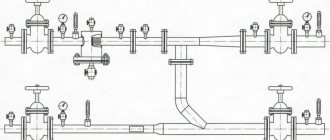
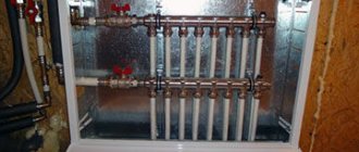
Rice. 1 Elevator unit of the heating system - examples of placement in heating networks
Principle of operation
To understand how the node works, it is necessary to give an example. To do this, we will take a three-story house, since the elevator unit is used specifically in multi-story buildings. The main part of the equipment that belongs to this system is located in the basement. The diagram below will help us better understand the work. We see two pipelines:
- The server.
- Back.
Diagram of a heating unit for a multi-storey building
Now you need to find on the diagram the thermal chamber through which water is sent to the basement. You can also notice shut-off valves, which must be installed at the entrance. The choice of fittings depends on the type of system. For the standard design, valves are used. But if we are talking about a complex system in a multi-story building, then the experts recommend using steel ball valves.
When connecting a thermal elevator unit, you must adhere to the standards. First of all, this concerns temperature conditions in boiler rooms. During operation, the following indicators are allowed:
When the liquid temperature is in the range of 70-95°C, it begins to be evenly distributed throughout the system due to the operation of the collector. If the temperature exceeds 95°C, the elevator unit begins to work to lower it, since hot water can damage equipment in the house, as well as shut-off valves. This is why this type of construction is used in multi-storey buildings - it controls the temperature automatically.
Areas of application and purpose
Having understood the heating unit diagram, you can proceed directly to installation work. As you know, such installations are often used in multi-apartment premises that are connected to a common communal heating system.
Thermal units are designed for such tasks:
- Checking and changing the operating properties of the coolant and thermal potential.
- Monitoring the current state of heating systems.
- Monitoring and recording the main indicators of the coolant - current temperature, pressure and volume.
- Carrying out cash calculations and drawing up an optimal energy expenditure plan.
When installing a heating system in a room, you need to understand that central heating requires certain costs. If we are talking about an apartment building, then all costs are divided among the residents. But sometimes they are unjustified due to the dishonest attitude of management companies and incorrect installation of system parts.
And in order to prevent significant financial damage, it is important to install in advance a highly efficient heating unit in a private home, which will automatically regulate any changes and select the optimal coolant temperature ratio. Only competent testing of equipment and proper maintenance will allow you to set up an effective heating system that will last for many years without failures.
Example of implementation of scheme 1 ACU
Schematic diagram of an automated control unit with a sufficient available pressure drop at the inlet
(P1 - P2 > 6 m water column) for temperatures up to AUU t = 95-70 °C
The modern world has long been unable to cope without innovative technologies. There is not a single technology or system that does not use revolutionary solutions. The heating system was no exception. This is due to the fact that this is a fairly significant technology, which is designed to ensure a comfortable existence.
For obvious reasons, special attention is paid when designing a house. Since ancient times, houses were built from the stove, that is, first the stove was built, and then it was covered with walls and a ceiling. This was done for a reason; for this we need to say “thank you” to our climate.
Starting from the middle zone of our spacious country and ending with distant Sakhalin, rather uncomfortable temperatures reign for most of the year. The thermometer ranges from +30 to -50 degrees.
Due to the rather complex temperature resonance, the heating system is as important as the electrical supply. Previously, a competent stove maker who knew how to make a proper stove was valued at the level of a blacksmith. After all, you need to correctly calculate the size of the firebox, the diameter of the chimney, and besides, the stove had to be multifunctional:
- food was prepared in it;
- it heated the room;
- warmed up the water;
- served as a small sleeping place.
That is why the construction of the furnace was complex and time-consuming. It had to have sufficient draft to ensure that all combustion products did not enter the room. But with all this, she had to be economical.
Today, fundamentally little has changed. The main functions and requirements for the heating system remain the same:
- saving;
- maximum efficiency;
- multifunctionality;
- simplicity of design;
- quality and durability;
- minimal operating costs;
- safety.
Fire was the first source of heat for humans. And even now its relevance has not lost its significance. The most primitive way of heating was to make a fire, which provided protection from predators, low temperatures, and served as a source of light.
Further, over time, humanity began to tame the gift of Hermes. Ovens appeared, they were usually built from clay and stones. Later, with the advancement of technology, ceramic bricks began to be used. And it was then that the first ones appeared.
Steel furnaces appeared much later; they determined the formation of the Steel Age. The fuel for the stoves was coal, wood, and peat. With the gasification of cities, furnaces became available. And all this time, man sought to improve the heating system.
Purpose and characteristics
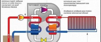
The heating elevator cools the superheated water to the design temperature, after which the prepared water enters the heating devices located in residential premises. Cooling of water occurs at the moment when hot water from the supply pipeline is mixed with cooled water from the return pipeline in the elevator.
Schematic diagram of the elevator unit
The heating elevator diagram clearly shows that this unit helps to increase the efficiency of the entire heating system of the building. It is assigned two functions at once - a mixer and a circulation pump. Such a unit is inexpensive and does not require electricity. But the elevator also has several disadvantages:
- The pressure difference between the direct and reverse supply pipelines should be 0.8-2 Bar.
- The output temperature cannot be adjusted.
- There must be an accurate calculation for each elevator component.
Elevators are widely used in municipal heating systems, since they are stable in operation when the thermal and hydraulic conditions in heating networks change. The heating elevator does not require constant monitoring; all regulation consists of choosing the correct nozzle diameter.
Elevator unit in the boiler room of an apartment building
The heating elevator consists of three elements - a jet elevator, a nozzle and a vacuum chamber. There is also such a thing as elevator piping. The necessary shut-off valves, control thermometers and pressure gauges must be used here.
The selection of a heating elevator of this type is due to the fact that here the mixing coefficient varies from 2 to 5, in comparison with conventional elevators without nozzle regulation, this indicator remains unchanged. Thus, in the process of using elevators with an adjustable nozzle, heating costs can be slightly reduced.
Elevator structure
The design of this type of elevator includes a regulating actuator that ensures stable operation of the heating system at low flow rates of network water. The cone-shaped nozzle of the elevator system houses a regulating throttle needle and a guide device, which spins the water stream and plays the role of a throttle needle casing.
This mechanism has a gear shaft rotating either electrically or manually. It is designed to move the throttle needle in the longitudinal direction of the nozzle, changing its effective cross-section, after which the water flow is regulated. Thus, you can increase the consumption of network water from the calculated indicator by 10-20%, or reduce it almost until the nozzle is completely closed. Reducing the nozzle cross-section can lead to an increase in the flow rate of network water and the mixing coefficient. This way the water temperature decreases.
Actuator mechanism of the heating elevator unit
How does an elevator work?
In simple terms, an elevator in a heating system is a water pump that does not require external energy. Thanks to this, and even its simple design and low cost, the element found its place in almost all heating points that were built in Soviet times. But for its reliable operation certain conditions are required, as will be discussed below.
To understand the structure of the heating system elevator, you should study the diagram presented in the figure above. The unit is somewhat reminiscent of a regular tee and is installed on the supply pipeline; with its side outlet it is connected to the return line. Only through a simple tee would water from the network pass directly into the return pipeline and directly into the heating system without reducing the temperature, which is unacceptable.
A standard elevator consists of a supply pipe (pre-chamber) with a built-in nozzle of the calculated diameter and a mixing chamber into which cooled coolant is supplied from the return. At the outlet of the assembly, the pipe expands, forming a diffuser. The unit operates as follows:
- coolant from the high-temperature network is directed to the nozzle;
- when passing through a hole of small diameter, the flow speed increases, which is why a rarefaction zone appears behind the nozzle;
- vacuum causes water to be sucked in from the return pipeline;
- the flows are mixed in the chamber and exit into the heating system through a diffuser.
An indispensable condition for stable operation of the unit is that the pressure difference between the supply and return lines of the heating network is greater than the hydraulic resistance of the heating system.
Along with obvious advantages, this mixing unit has one significant drawback. The fact is that the operating principle of the heating elevator does not allow regulating the temperature of the mixture at the outlet. After all, what is needed for this? If necessary, change the amount of superheated coolant from the network and sucked water from the return. For example, in order to reduce the temperature, it is necessary to reduce the supply flow and increase the flow of coolant through the jumper. This can only be achieved by reducing the nozzle diameter, which is impossible.
Don't miss: Bypass and check valves
Electric elevators help solve the problem of quality regulation. In them, by means of a mechanical drive rotated by an electric motor, the diameter of the nozzle increases or decreases. This is achieved through a cone-shaped throttle needle that enters the nozzle from the inside at a certain distance. Below is a diagram of a heating elevator with the ability to control the temperature of the mixture:
1 – nozzle; 2 – throttle needle; 3 – actuator housing with guides; 4 – shaft with gear drive.
Note. The drive shaft can be equipped with either a handle for manual control or an electric motor activated remotely.
The adjustable heating elevator, which appeared relatively recently, allows for the modernization of heating points without a radical replacement of equipment. Considering how many other similar units operate in the CIS, such units are becoming increasingly relevant.
What is an elevator unit of a heating system?
Multi-storey buildings, high-rise buildings, administrative buildings and many different consumers provide heat from combined heat and power plants or powerful boiler houses. Even a relatively simple autonomous system in a private home is sometimes difficult to adjust, especially if errors were made during the design or installation. But the heating system of a large boiler house or thermal power plant is incomparably more complex. There are many branches leaving the main pipe, and each consumer has different pressure in the heating pipes and the amount of heat consumed.
Pipe lengths vary and the system must be designed so that the furthest consumer receives sufficient heat. It becomes clear why there is coolant pressure in the heating system. Pressure moves water along the heating circuit, i.e. created by the central heating line, it plays the role of a circulation pump. The heating system must not allow imbalance when the heat consumption of any consumer changes.
In addition, the efficiency of heat supply should not be affected by the branching of the system. In order for a complex centralized heating system to operate stably, it is necessary to install either an elevator unit or an automated heating system control unit at each facility to eliminate mutual influence between them.
Switchgears
The elevator unit with all its piping can be thought of as a pressure circulation pump, which supplies coolant to the heating system under a certain pressure.
If the facility has several floors and consumers, then the most correct solution is to distribute the total coolant flow to each consumer.
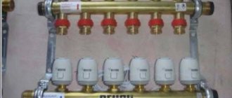
To solve such problems, a comb is designed for the heating system, which has another name - a collector. This device can be represented as a container. The coolant flows into the container from the elevator outlet, which then flows out through several outlets, with the same pressure.
Consequently, the distribution comb of the heating system allows the shutdown, adjustment, and repair of individual consumers of the facility without stopping the operation of the heating circuit. The presence of a collector eliminates the mutual influence of the heating system branches. In this case, the pressure in the heating radiators corresponds to the pressure at the elevator outlet.
How is the thermal unit arranged?
In general, the technical structure of each heating point is designed separately depending on the specific requirements of the customer. There are several basic schemes for the design of heating points. Let's look at them one by one.
Thermal unit based on an elevator
The scheme of a heating point based on an elevator unit is the simplest and cheapest. Its main drawback is the inability to regulate the temperature of the coolant in the pipes. This causes inconvenience for the end user and a large overconsumption of thermal energy in the event of thaws during the heating season. Let's look at the figure below and understand how this circuit works:
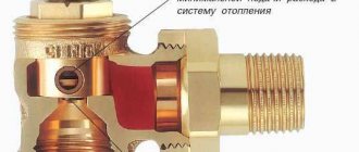
In addition to what is indicated above, the thermal unit may include a pressure reducer. It is installed on the feed in front of the elevator. The elevator is the main part of this scheme, in which the cooled coolant from the “return” is mixed with the hot coolant from the “supply”. The operating principle of the elevator is based on creating a vacuum at its output. As a result of this vacuum, the coolant pressure in the elevator is less than the coolant pressure in the “return” and mixing occurs.
Thermal unit based on a heat exchanger.
A heating point connected through a special heat exchanger allows you to separate the coolant from the heating main from the coolant inside the house. The separation of coolants allows for its preparation using special additives and filtration. With this scheme, there are ample opportunities to regulate the pressure and temperature of the coolant inside the house. This allows you to reduce heating costs. To have a clear idea of this design, look at the figure below.
The mixing of coolant in such systems is done using thermostatic valves. In such heating systems, in principle, aluminum radiators can be used, but they will last for a long time only if the coolant is of good quality. If the PH of the coolant goes beyond those approved by the manufacturer, then the service life of aluminum radiators may be greatly reduced. You cannot control the quality of the coolant, so it is better to play it safe and install bimetallic or cast iron radiators.
DHW can be connected in a similar way via a heat exchanger. This offers the same benefits in terms of hot water temperature and pressure control. It is worth saying that unscrupulous management companies can deceive consumers by lowering the hot water temperature by a couple of degrees. For the consumer, this is almost unnoticeable, but on a household scale it allows you to save tens of thousands of rubles per month.
Main disadvantages
Despite the fact that the elevator unit has many advantages, it also has one significant drawback. It’s just that the elevator circuit does not provide for the possibility of adjusting the temperature of the outgoing coolant. If the return water temperature indicates that it is very hot, you will need to reduce it. This problem can only be solved by reducing the size of the nozzle, but this cannot always be done due to the design features of the equipment.
In some cases, the heating unit is equipped with an electric drive, thanks to which the size of the nozzle can be adjusted. It moves the main structural element - the throttle cone needle. This needle moves a certain distance into the hole inside the nozzle. The depth of movement makes it possible to change the diameter of the nozzle and thereby regulate the temperature of the coolant.
Both a manual drive in the form of a handle and a remotely controlled electric motor can be installed on the shaft.
It must be said that the installation of this temperature regulator makes it possible to improve the overall heating system with a thermal unit without significant material costs.
Malfunctions of heating elevators
The diagram of the elevator heating unit may have faults that are caused by a breakdown of the elevator itself (clogging, an increase in the diameter of the nozzle), clogging of mud traps, breakdown of fittings, or violations of the regulator settings.
Small elevator heating unit
The breakdown of an element such as a heating elevator device can be noticed by the way temperature differences appear before and after the elevator. If the difference is large, then the elevator is faulty; if the difference is insignificant, then it may be clogged or the nozzle diameter may be increased. In any case, diagnosis of the breakdown and its elimination should only be carried out by a specialist!
Devices installed on the lower floors will overheat, and those on the upper floors will not receive enough heat. Such a malfunction, which the operation of the heating elevator undergoes, is eliminated by replacing it with a new nozzle with the calculated diameter.
Maintenance of the elevator heating unit
Clogging of the sump in a device such as an elevator in a heating system can be determined by the increase in the pressure difference, monitored by pressure gauges before and after the sump. Such clogging is removed by discharging dirt through the drain valves of the sludge tank, which are located in its lower part. If the blockage is not removed this way, then the mud trap is disassembled and cleaned from the inside.
Possible problems and malfunctions
Despite the durability of the devices, sometimes the elevator heating unit malfunctions. Hot water and high pressure quickly find weak points and cause breakdowns.
This inevitably happens when individual components are assembled of poor quality, the calculation of the nozzle diameter is incorrect, and also due to the formation of blockages.
Noise
The heating elevator may create noise when operating. If this is observed, it means that cracks or scuffs have formed in the outlet part of the nozzle during operation.
The reason for the appearance of irregularities lies in the distortions of the nozzle caused by the supply of coolant under high pressure. This happens if the excess pressure is not throttled by the flow regulator.
Temperature mismatch
The quality operation of the elevator can also be questioned when the inlet and outlet temperatures differ too much from the temperature curve. Most likely, the reason for this is the oversized nozzle diameter.
Incorrect water flow
A faulty throttle will result in a change in water flow compared to the design value.
Such a violation can be easily determined by changes in temperature in the incoming and return piping systems. The problem is solved by repairing the flow regulator (throttle).
Faulty structural elements
If the connection diagram of the heating system to the external heating main has an independent form, then the cause of poor-quality operation of the elevator unit can be caused by faulty pumps, water heating units, shut-off and safety valves, all kinds of leaks in pipelines and equipment, and malfunction of regulators.
The main reasons that negatively affect the design and principle of operation of pumps include the destruction of elastic couplings in the connections of the pump and electric motor shafts, wear of ball bearings and destruction of seats for them, the formation of fistulas and cracks in the housing, aging of oil seals. Most of the listed faults can be eliminated by repair.
Unsatisfactory operation of water heaters occurs when the tightness of the pipes is broken, they are destroyed or the tube bundle sticks together. The solution to the problem is to replace the pipes.
Blockages
Blockages are one of the common causes of poor heat supply. Their formation is associated with dirt entering the system when dirt filters are faulty. Deposits of corrosion products inside pipes also increase the problem.
The level of filter clogging can be determined by the readings of pressure gauges installed before and after the filter. A significant pressure drop will confirm or refute the assumption about the degree of clogging. To clean the filters, it is enough to remove dirt through the drainage devices located in the lower part of the housing.
Any problems with pipelines and heating equipment must be corrected immediately.
Minor comments that do not affect the operation of the heating system are necessarily recorded in special documentation and are included in the plan for current or major repairs. Repairs and corrections take place in the summer before the start of the next heating season.
Features of the operation of central heating stations, installation of heating points
The heating system is fed by the return pipeline of the heating network. Heat sources and thermal energy transport systems The heat source for TPs are heat generating enterprises, boiler houses, and combined heat and power plants.
Water from the external water supply network is supplied to the DHW heater.
Compensation for the decrease in pressure level is carried out through a group of pumps. Viewed: The DHW circuit can be designated as single-stage, independent and parallel.
Correction mode is automatic. Often, heat from the domestic hot water system is used by consumers for partial heating of premises, for example bathrooms in multi-apartment residential buildings. The flow of hot mains water to the 2nd stage heater is controlled by the temperature controller (thermal relay valve) depending on the water temperature behind the 2nd stage heater.
The schematic diagram of an individual heating point is approved.
Certificate for flushing and pressure testing of heating networks, heating systems and hot water supply systems.
All this equipment must operate exclusively in automatic mode, so it is critically important to correctly set up the entire set of equipment for work in a particular home
Central heating stations should be located on the boundaries of microdistricts between the main, distribution networks and quarterly ones. One of them is the heating system. If there is a central heating point in each individual building, it is necessary to install an ITP, which performs only those functions that are not provided for in the central heating point and are necessary for the heat consumption system of a given building.
This device can be represented as a container. But the cost of such a device is much higher, although its use is more economical. Heat consumption is controlled and taken into account. After the elevator, the return line will also be counted.
After the elevator unit, the mixed coolant is supplied to the heating system of the building. The installation company must be a member of the SRO. Further, as the most common, we consider a TP with a closed hot water supply system and an independent connection circuit for the heating system. Creating a schematic diagram of an individual heating point in AutoCAD P&ID
Common breakdowns and methods for eliminating them
Despite the simplicity of the design, the elevator can fail. Breakdowns occur for various reasons, but most often this is caused by contamination, failure of fittings and regulators, incorrect settings, incorrect nozzle diameter or clogged mud traps.
Depending on the breakdown, there are different ways to repair an elevator:
- If the cause of the malfunction is a clogged nozzle, it must be removed and cleaned.
- If the diameter of the nozzle has changed due to corrosion or erosion by water, then the part is replaced with a new one. When choosing a new nozzle, it is important to accurately select its diameter. Otherwise, this will cause an imbalance in the system and severe overheating of the heating radiators on the first floor of the house against the background of a decrease in heat transfer from devices on the upper floors.
- When the mud traps become clogged, you can guess this by the increased pressure difference between the supply and return pipelines. To control the pressure before and after the filters, pressure gauges are installed. To clear the blockage, open the drain valve on the sump itself. It is located at the bottom of the device. If these actions do not lead to the desired result, then you will have to disassemble the mud collector and clean its component parts separately.
What is an elevator unit?
The elevator unit of the heating system is a device of a certain type that performs the functions of an injection or water-jet pump. The main tasks are to increase the pressure inside the heating system, increase the pumping of coolant through the network, and increase volume growth.
A durable thermal unit can transport significantly overheated coolant, which is economically beneficial. For example, one ton of water heated to +150 C contains much more thermal energy than the same volume with indicators of +90 C. The use of a thermal unit ensures rapid movement of the carrier through the system, without turning the liquid substance into steam - this property is constantly explained maintained pressure that keeps the carrier in an aggregate liquid state.
Operating principle and unit diagram
Algorithm for the operation of the elevator jumper:
- The heated coolant passes through the pipe in the direction of the nozzle, then under pressure the flow accelerates and the effect of a water-jet pump is started. Therefore, while water passes through the nozzle, the circulation of the media in the system is ensured.
- At the moment the liquid passes through the mixing chamber, the pressure level decreases to normal and the jet, entering the diffuser, provides a vacuum in the mixing chamber. According to the ejection effect, the coolant with an increased pressure indicator carries water through the jumper, which returns from the heating network.
- Mixing of the cooled and heated flow occurs in the heating elevator chamber, therefore, when leaving the diffuser, the flow temperature drops to +95 C.
Having considered what a heating unit is in an apartment building and the principle of operation of an elevator, you should know that for the normal functionality of the unit it is important to ensure the proper pressure difference in the main and return lines. The difference in indicators is needed to overcome the hydraulic resistance of the heating system in the house and the device itself,
Externally, the elevator looks like a large tee made of metal pipes, equipped with connecting flanges at the ends. But if you look at the drawing, the structure of the thermal unit elevator from the inside is more complex:
- the left pipe looks like a nozzle tapering to the calculated diameter;
- immediately behind the nozzle there is a mixing chamber cylinder;
- connection of the return line is achieved through the lower pipe;
- the pipe on the right is an expansion diffuser that directs hot water into the heating system.
A detailed diagram of the elevator heating unit is required when connecting the system. The connection is made as follows: the left pipe is to the supply line of the central network, the bottom pipe is to the pipeline with the return flow. Shut-off valves must be installed on both sides, supplemented with a mesh filter, which is needed to filter out large particles and inclusions. The design of the heating point is also complemented by pressure gauges, thermometers and heat meters.
Advantages and disadvantages of a thermal unit
Despite the obsolescence of the equipment, the simplicity of the design and low cost explain the demand for the heating elevator. The device does not need to be connected to the mains; it operates independently of energy. Many users argue that the scheme is irrational and if the efficiency of the device is low (up to 30%), the heating of the coolant should be reduced by abandoning the unit.
But if you remove the heating elevator, then the diameter of the main pipes will have to be significantly increased in order to ensure normal coolant flow at a lower temperature, and this will lead to additional costs. Therefore, it is premature to abandon the jet pump.
The disadvantages include the inability to control the water temperature, but when using devices with adjustable nozzle diameter, the minus is leveled out. Adjusting the nozzle will help control the speed of the supplied coolant, change the vacuum parameters in the mixer chamber and, as a result, control the water supply temperature.
Diagrams of thermal units
If we talk about the schemes of heating points, it should be noted that the most common types are the following:
Thermal unit is a circuit with a parallel single-stage hot water connection. This scheme is the most common and simple. In this case, the hot water supply is connected in parallel to the same network as the heating system of the building. The coolant is supplied to the heater from the external network, then the cooled liquid flows in the reverse order directly into the heat pipe. The main disadvantage of such a system, compared to other types, is the high consumption of network water, which is used to organize hot water supply.
Diagram of a heating point with a sequential two-stage connection of hot water. This scheme can be divided into two stages. The first stage is responsible for the return pipeline of the heating system, the second - for the supply pipeline. The main advantage of thermal units connected according to this scheme is the absence of a special supply of network water, which significantly reduces its consumption. As for the disadvantages, this is the need to install an automatic control system to configure and adjust the heat distribution. This connection is recommended to be used if the ratio of the maximum heat consumption for heating and hot water supply is in the range from 0.2 to 1.
Thermal unit is a circuit with a mixed two-stage connection of a hot water heater. This is the most universal and flexible connection scheme. It can be used not only for normal temperature schedules, but also for elevated ones. The main distinguishing feature is the fact that the heat exchanger is connected to the supply pipeline not in parallel, but in series. The further principle of the structure is similar to the second scheme of the heating point. Thermal units connected according to the third scheme require additional consumption of network water for the heating element.
Elevator components and equipment
An elevator is not one building, it is a complex of interconnected objects. The objects are as follows:
The list of equipment necessary for the operation of the elevator includes:
- elevators, which are necessary for delivering grain for weighing, cleaning from impurities and drying. The vertical belt continuously makes a cyclic movement, at the bottom it scoops up grain with buckets, at the top point the buckets tip over, pouring out the contents;
- a screw conveyor, with the help of which the grain crop is transferred to conveyors that dump it into a silo;
- equipment for loading and unloading grain crops.
Old style elevator
About the heating system
If we talk about multi-apartment buildings, then they often have centralized heating installed, which supplies heat to all living spaces.
In country, private houses, autonomous heating systems are more common, made, in some cases, from cross-linked polyethylene pipes for heating.
But whatever heat supply system you have, it requires proper use, care, and careful attention.
One of the main elements of the heating system is the elevator unit.
Most people do not know about such a unit, but we will try to correct this by providing all the necessary information in this article.
This detail is present in any heating system, including modern ones, with heated floors (watch the video of the installation of cross-linked polyethylene pipes here), the elevator can be seen if you go into the basement.
But in order to appreciate its purpose, it is necessary to understand the heat supply circuit in any heating system.
So, the main source of heat is hot water, it is supplied to the house through a pipeline.
There is not one pipeline, but two, each of which performs its own important function:
- one supplies hot water to the building from the boiler room to the house;
- There is also a return pipeline that supplies the used coolant (cooled water) back to the boiler room.
Only hot water can enter the building's heating system from the boiler room's heat chamber. At the entrance to the thermal unit there is a special shut-off valve or a steel ball valve.
The second option is more reliable and modern; in new buildings, it is usually used.
Next, the hot water moves depending on how hot it is.
There are standards for water temperature, it must have one of the above temperatures:
- 95/70 degrees;
- 130/70 degrees;
- 150/70.
If the coolant is heated to a temperature below 95 C, it will be directed evenly throughout the system.
For this purpose, there are special collectors that regulate the distribution of water using balancing taps.
Operating principle
The best example that will show the operating principle of a heating elevator would be a multi-storey building. It is in the basement of a multi-story building that you can find an elevator among all the elements.
First of all, let's look at the drawing of the elevator heating unit in this case. There are two pipelines: supply (it is through it that hot water goes to the house) and return (cooled water returns to the boiler room).
Diagram of an elevator heating unit
From the thermal chamber, water enters the basement of the house; there is always a shut-off valve at the entrance. Usually these are valves, but sometimes in those systems that are more thought out, steel ball valves are installed.
As the standards show, there are several thermal regimes in boiler rooms:
- 150/70 degrees;
- 130/70 degrees;
- 95(90)/70 degrees.
When the water heats up to a temperature no higher than 95 degrees, the heat will be distributed throughout the heating system using a collector. But at temperatures above normal - above 95 degrees, everything becomes much more complicated. Water at this temperature cannot be supplied, so it must be reduced. This is precisely the function of the elevator heating unit. We also note that cooling water in this way is the simplest and cheapest way.
Search the site otoplenie-doma.org
Control
We present the procedure for performing some operations related to the operation of the elevator.
Start heating
If the system is full, you just need to open the house valves and circulation will begin.
The instructions for starting a reset system are somewhat more complicated.
- The discharge on the return line opens and the discharge on the supply line closes.
- Slowly (to avoid water hammer) the upper house valve opens.
- After clean, air-free water flows into the discharge, it closes, after which the lower house valve opens.
Work without nozzle
When the return temperature is catastrophically low during the peak of cold weather, it is practiced to operate the elevator without a nozzle. The system receives coolant from the route, not the mixture. The suction is suppressed with a steel pancake.
Differential adjustment
If the return flow is too high and it is impossible to quickly replace the nozzle, adjusting the differential with a valve is practiced.
How to do it yourself?
- The supply pressure is measured, after which the pressure gauge is placed on the return line.
- The inlet valve on the return line closes completely and gradually opens with pressure control using a pressure gauge. If you simply close the valve, its cheeks may not completely move down the stem and will slide down later. The price of the wrong procedure is guaranteed defrosted access heating.
No more than 0.2 atmospheres of difference should be removed at a time.
The return temperature is re-measured a day later, when all values have stabilized. Date: September 25, 2022