Control
The controlling organization is, again, heating networks.
What exactly do they control?
- Several times during the winter, control measurements are taken of the temperatures and pressures of the supply, return and mixture
. In case of deviations from the temperature curve, the calculation of the heating elevator is carried out again with boring or reducing the diameter of the nozzle. Of course, this should not be done during the peak of cold weather: at -40 outside, the access heating system can become covered with ice within an hour after the circulation stops. - In preparation for the heating season, the condition of the shut-off valves is checked
. The check is extremely simple: all valves in the assembly are closed, after which any control valve opens. If water comes from it, you need to look for a fault; In addition, in any position of the valves, they should not have leaks through the seals. - Finally, at the end of the heating season, the elevators in the heating system, along with the system itself, are tested for temperature. When the DHW supply is turned off, the coolant heats up to maximum values.
How does an elevator unit work in a district heating scheme?
Elevator units have been used in heating units of apartment buildings since the middle of the last century, and some examples continue to operate successfully to this day. Residents are in no hurry to replace obsolete elements with new fittings equipped with modern automation, and this reluctance is completely justified. To clarify the essence of the issue, we suggest understanding what an elevator is, its structure and the main functions in the heating system.
Purpose and characteristics
The heating elevator cools the superheated water to the design temperature, after which the prepared water enters the heating devices located in residential premises. Cooling of water occurs at the moment when hot water from the supply pipeline is mixed with cooled water from the return pipeline in the elevator.
The heating elevator diagram clearly shows that this unit helps to increase the efficiency of the entire heating system of the building. It is assigned two functions at once - a mixer and a circulation pump. Such a unit is inexpensive and does not require electricity. But the elevator also has several disadvantages:
- The pressure difference between the direct and reverse supply pipelines should be 0.8-2 Bar.
- The output temperature cannot be adjusted.
- There must be an accurate calculation for each elevator component.
Elevators are widely used in municipal heating systems, since they are stable in operation when the thermal and hydraulic conditions in heating networks change. The heating elevator does not require constant monitoring; all regulation consists of choosing the correct nozzle diameter.
The heating elevator consists of three elements - a jet elevator, a nozzle and a vacuum chamber. There is also such a thing as elevator piping. The necessary shut-off valves, control thermometers and pressure gauges must be used here.
The selection of a heating elevator of this type is due to the fact that here the mixing coefficient varies from 2 to 5, in comparison with conventional elevators without nozzle regulation, this indicator remains unchanged. Thus, in the process of using elevators with an adjustable nozzle, heating costs can be slightly reduced.
The design of this type of elevator includes a regulating actuator that ensures stable operation of the heating system at low flow rates of network water. The cone-shaped nozzle of the elevator system houses a regulating throttle needle and a guide device, which spins the water stream and plays the role of a throttle needle casing.
This mechanism has a gear shaft rotating either electrically or manually. It is designed to move the throttle needle in the longitudinal direction of the nozzle, changing its effective cross-section, after which the water flow is regulated. Thus, you can increase the consumption of network water from the calculated indicator by 10-20%, or reduce it almost until the nozzle is completely closed. Reducing the nozzle cross-section can lead to an increase in the flow rate of network water and the mixing coefficient. This way the water temperature decreases.
What is an elevator heating unit and what is it used for?
In order to clearly understand the structure and purpose of the elevator unit, you can go into an ordinary basement of a multi-story building. There, among the other elements of the thermal unit, you can find the required part.
Elevator heating unit
Let's consider a schematic diagram of the coolant supply to the heating system of a residential building. Hot water is supplied through pipelines to the house. It is worth noting that there are only two pipelines, of which:
- 1- supply (supplies hot water to the house);
- 2-reverse (removes the coolant that has released heat back to the boiler room);
Water heated to a certain temperature from the thermal chamber enters the basement of the building, where shut-off valves are installed on the pipelines at the entrance to the heating unit. Previously, gate valves were installed everywhere as shut-off valves; now they are gradually being replaced by ball valves made of steel. The further path of the coolant depends on its temperature.
In our country, boiler houses operate according to three main thermal regimes:
If the water in the supply pipeline is heated to no more than 95 0 C, then it is simply distributed throughout the heating system using a manifold equipped with control devices (balancing valves). If the temperature of the coolant is above 95 0 C, then according to current standards such water cannot be supplied to the heating system. You need to cool it down. This is where the elevator unit comes into play. It is worth noting that the elevator heating unit is the cheapest and simplest way to cool the coolant.
Effect of installing washers
After installing the washers, the coolant flow through the pipelines of the heating network is reduced by 1.5-3 times. Accordingly, the number of operating pumps in the boiler room also decreases. This results in savings in fuel, electricity, and chemicals for make-up water. It becomes possible to increase the temperature of the water leaving the boiler room. For more information about setting up external heating networks and the scope of work, see.....Here you need to provide a link to the section of the site “Setting up heating networks”
Washers are necessary not only for regulating external heating networks, but also for heating systems inside buildings. The heating system risers, located further from the heating station located in the house, receive less hot water; here the apartments are cold. It is hot in apartments located close to the heating station, as more coolant flows to them. The distribution of coolant flows among the risers in accordance with the required amount of heat is also carried out by calculating the washers and their installation on the risers.
How to order and buy a water jet elevator 40s10bk?
In order to buy an elevator, you must send a request to the sales department using the coordinates on the CONTACTS . The request must indicate the elevator number and quantity, as well as the need for delivery. A price offer will be sent to you in response, indicating the current cost and availability of the goods in stock.
You can also send a request using a special form - SEND A REQUEST on the website.
Delivery is carried out by transport companies to all regions of the Russian Federation. It is possible to ship products to the countries of the Customs Union (Armenia, Belarus, Kazakhstan, Kyrgyzstan). Delivery costs are calculated and paid additionally.
Stages of washer heating system
- Hydraulic calculation of the heating system, calculation of washers
- Development of recommendations for improving the operation of the heating station and heating system
- Installation of control washers on risers (the customer can carry out this work independently)
- Checking the implementation of recommended measures
- Analysis of the new steady state after washing the heating system
- Adjusting the size of washers in places where the required result has not been achieved (by calculation)
- Removing washers that require adjustment, installing new washers
On internal heating systems, washers can be installed in both winter and summer. Check their operation only during the heating season.
Possible problems and malfunctions
Despite the durability of the devices, sometimes the elevator heating unit malfunctions. Hot water and high pressure quickly find weak points and cause breakdowns.
This inevitably happens when individual components are assembled of poor quality, the calculation of the nozzle diameter is incorrect, and also due to the formation of blockages.
Noise
The heating elevator may create noise when operating. If this is observed, it means that cracks or scuffs have formed in the outlet part of the nozzle during operation.
The reason for the appearance of irregularities lies in the distortions of the nozzle caused by the supply of coolant under high pressure. This happens if the excess pressure is not throttled by the flow regulator.
Temperature mismatch
The quality operation of the elevator can also be questioned when the inlet and outlet temperatures differ too much from the temperature curve. Most likely, the reason for this is the oversized nozzle diameter.
Incorrect water flow
A faulty throttle will result in a change in water flow compared to the design value.
Such a violation can be easily determined by changes in temperature in the incoming and return piping systems. The problem is solved by repairing the flow regulator (throttle).
Faulty structural elements
If the connection diagram of the heating system to the external heating main has an independent form, then the cause of poor-quality operation of the elevator unit can be caused by faulty pumps, water heating units, shut-off and safety valves, all kinds of leaks in pipelines and equipment, and malfunction of regulators.
The main reasons that negatively affect the design and principle of operation of pumps include the destruction of elastic couplings in the connections of the pump and electric motor shafts, wear of ball bearings and destruction of seats for them, the formation of fistulas and cracks in the housing, aging of oil seals. Most of the listed faults can be eliminated by repair.
Unsatisfactory operation of water heaters occurs when the tightness of the pipes is broken, they are destroyed or the tube bundle sticks together. The solution to the problem is to replace the pipes.
Blockages
Blockages are one of the common causes of poor heat supply. Their formation is associated with dirt entering the system when dirt filters are faulty. Deposits of corrosion products inside pipes also increase the problem.
The level of filter clogging can be determined by the readings of pressure gauges installed before and after the filter. A significant pressure drop will confirm or refute the assumption about the degree of clogging. To clean the filters, it is enough to remove dirt through the drainage devices located in the lower part of the housing.
Any problems with pipelines and heating equipment must be corrected immediately.
Minor comments that do not affect the operation of the heating system are necessarily recorded in special documentation and are included in the plan for current or major repairs. Repairs and corrections take place in the summer before the start of the next heating season.
Connection diagrams
The elevator unit can be used in systems with various specific features - single-pipe, autonomous or other heat supply lines. The principles of coolant supply and flow parameters do not always allow for a constant and stable output result. To organize normal heat supply to apartments or adjust the flow parameters coming from the main network, various connection schemes for elevator units are used. All of them require additional equipment, sometimes in quite large quantities, but the result achieved as a result of this compensates for the costs incurred. Let's look at the existing connection diagrams:
With water flow regulator
Water consumption is the main factor that makes it possible to adjust the heating mode of the premises. Changes in flow cause temperature fluctuations in living rooms, which is unacceptable. The issue is resolved by installing a regulator in front of the mixing unit, which ensures constant water flow and stabilizes the thermal regime.
Diagram of an elevator mixing unit with a flow regulator: 1 - supply line of the heating network; 2 - return line of the heating network; 3 - elevator; 4 - flow regulator; 5 - local heating system
This solution becomes especially important in single-pipe systems, where there is a load in the form of hot water supply, which destabilizes the flow of hot water and creates significant fluctuations during active water withdrawal (morning and evening hours, holidays and weekends). At the same time, this scheme is not able to correct the situation when the temperature of the coolant in the main line changes, which is its drawback, although not too significant. A drop in coolant temperature in the supply pipelines means an accident at a thermal power plant or other heating point, and this rarely happens.
With regulating nozzle
The connection diagram of the elevator unit with the ability to adjust the nozzle capacity allows you to quickly respond to changes in coolant parameters in the main line.
Diagram of an elevator unit with a regulating needle: 1 - supply line of the heating network; 2 - return line of the heating network; 3 - elevator; 5 - local heating system; 6 - regulator with a needle pushed into the elevator nozzle
At the same time, manual adjustment is ineffective, since for this you need to constantly approach the elevator, which is usually located in the basement. The greatest efficiency of a system with an adjustable nozzle is achieved with complete automation of the process, using temperature and pressure sensors that send a signal to the elevator servo drive. This scheme allows you to gain additional opportunities when setting the operating mode, but the need for it does not always arise, but only in overloaded or unstable systems with possible fluctuations in coolant temperature.
Diagram of an elevator unit using temperature and pressure sensors that send a signal to the elevator servo drive
The disadvantages of such schemes include the need to initially ensure high pressure in the system, since adjustment is possible only within the limits of the flow parameters in the line. In addition, loads on the mechanics, in particular on the nozzle and needle, create the need for constant monitoring and timely replacement of failed elements.
With control pump
Such schemes are used in the absence of sufficient pressure in the supply pipelines for the operation of the elevator.
Diagram of an elevator unit with a correction pump: 1 - supply line of the heating network; 2 - return line of the heating network; 3 - elevator; 4 - flow regulator; 5 - local heating system; 7 — temperature controller; 8 - mixing pump
An increase in pressure makes it possible to use an elevator unit in the autonomous heating networks of a private house and allows for circulation of the coolant when the pressure in the main disappears. The pump is installed in front of the elevator or on the jumper between the forward and return pipelines before entering the elevator. To ensure normal operation, a temperature controller must be used in addition to the pump, and a power supply must be connected.
Operating principle and unit diagram
The hot water entering a residential building has a temperature corresponding to the temperature schedule of the combined heat and power plant. Having overcome the valves and dirt filters, the superheated water enters the steel body, and then through the nozzle into the chamber where mixing occurs. The pressure difference pushes a stream of water into the expanded part of the housing, and it connects with the cooled coolant from the heating system of the building.
The superheated coolant, having a reduced pressure, rushes at high speed through the nozzle into the mixing chamber, creating a vacuum. As a result, in the chamber behind the jet, the effect of injection (suction) of coolant from the return pipeline occurs. The result of mixing is water at the design temperature, which enters the apartments.
The elevator device diagram gives a detailed idea of the functionality of this device.
Advantages of water jet elevators
A special feature of the elevator is the simultaneous performance of two tasks: to work as a mixer and as a circulation pump. It is noteworthy that the elevator unit operates without the cost of electricity, since the operating principle of the installation is based on the use of differential pressure at the inlet.
The use of water jets has its advantages:
- simple design;
- low cost;
- reliability;
- no need for electricity.
Using the latest models of elevators equipped with automation, you can significantly save heat. This is achieved by regulating the temperature of the coolant in its outlet area. To achieve this goal, you can lower the temperature in apartments at night or during the day, when most people are at work, study, etc.
The economical elevator unit differs from the conventional version by the presence of an adjustable nozzle. These parts can have different designs and levels of adjustment. The mixing coefficient of a device with an adjustable nozzle varies from 2 to 6. As practice has shown, this is quite sufficient for the heating system of a residential building.
The principle of operation of the elevator
Externally, the design resembles a large tee made of metal pipes with connecting flanges at the ends. How the elevator works inside:
- the left nozzle (see drawing) is a tapering nozzle of the calculated diameter;
- behind the nozzle there is a cylindrical mixing chamber;
- the lower pipe is used to connect the return line to the mixing chamber;
- the right pipe is an expanding diffuser that directs coolant into the heating network of a multi-story building.
In the drawing, the ejected flow pipe is conventionally shown at the top, although it is usually located at the bottom
Note. In the classic version, the elevator does not require connection to the house electrical network. An updated version of the product with an adjustable nozzle and an electric drive is connected to an external power source.
The steel elevator unit is connected by the left branch pipe to the supply line of the centralized heating network, and by the bottom branch pipe to the return pipeline. Shut-off valves are installed on both sides of the element, plus a mesh filter - a sump (otherwise known as a sludge tank) on the supply. The traditional scheme of a heating point with an elevator also includes pressure gauges, thermometers (on both lines) and a meter for energy consumption.
Now let's look at how the elevator jumper works:
- Superheated water from the heating network passes through the left pipe to the nozzle.
- At the moment of passing through the narrow section of the nozzle under high pressure, the flow accelerates according to Bernoulli's law. The effect of a water jet pump begins to operate, ensuring the circulation of coolant in the system.
- In the area of the mixing chamber, the water pressure decreases to normal.
- The jet moving at high speed into the diffuser creates a vacuum in the mixing chamber. An ejection effect occurs - a flow of liquid with a higher pressure entrains the coolant returning from the heating network through the jumper.
- In the heating elevator chamber, the cooled water is mixed with superheated water, and at the outlet of the diffuser we obtain the coolant at the required temperature (up to 95 °C).
Clarification. It is worth noting that the elevator unit also uses the injection principle in its operation - mixing two jets with simultaneous transfer of energy. The pressure of the resulting flow becomes less than the initial one, but more than that sucked from the return. The process is shown more clearly in the video:
The main condition for normal operation of the elevator is a sufficient pressure difference between the main supply and the return line. This difference should be enough to overcome the hydraulic resistance of the home heating system and the injector itself. Please note: the vertical jumper cuts into the return at an angle of 45° for better flow separation.
At the supply from the heating network, the pressure is highest, at the outlet from the diffuser - average, in the return line - the lowest. The same thing happens in the elevator with water temperature
Selection of material for ETA-P elevator parts
When choosing a material for a particular part, take into account the nature and magnitude of the load acting on the part, the manufacturing method, requirements for wear resistance, conditions of its operation, etc.
Particular attention is paid to ensuring static and fatigue strength, since the service life of parts ranges from 10 to 25 years. For the manufacture of elevators, high-quality carbon structural steels of grades 30, 35, 40, 45, 40Х and 40ХН are used
They are used in a normalized state for the manufacture of parts experiencing relatively low stresses, and after hardening and high tempering - for the manufacture of more loaded parts. Steel grades 30 and 35 are subjected to normalization at a temperature of 880 - 900 ° C; hardening is carried out in water at a temperature of 860 - 880°C and tempering at 550 - 660°C. Parts made from steel grades 40 and 45 are subjected to normalization at a temperature of 860-880°C or quenching in water at a temperature of 840-860°C, followed by tempering; The tempering temperature is set depending on the required mechanical properties.
How does an elevator work?
In simple terms, an elevator in a heating system is a water pump that does not require external energy. Thanks to this, and even its simple design and low cost, the element found its place in almost all heating points that were built in Soviet times. But for its reliable operation certain conditions are required, as will be discussed below.
To understand the structure of the heating system elevator, you should study the diagram presented in the figure above. The unit is somewhat reminiscent of a regular tee and is installed on the supply pipeline; with its side outlet it is connected to the return line. Only through a simple tee would water from the network pass directly into the return pipeline and directly into the heating system without reducing the temperature, which is unacceptable.
A standard elevator consists of a supply pipe (pre-chamber) with a built-in nozzle of the calculated diameter and a mixing chamber into which cooled coolant is supplied from the return. At the outlet of the assembly, the pipe expands, forming a diffuser. The unit operates as follows:
- coolant from the high-temperature network is directed to the nozzle;
- when passing through a hole of small diameter, the flow speed increases, which is why a rarefaction zone appears behind the nozzle;
- vacuum causes water to be sucked in from the return pipeline;
- the flows are mixed in the chamber and exit into the heating system through a diffuser.
How the described process occurs is clearly shown by the diagram of the elevator unit, where all flows are marked in different colors:
An indispensable condition for stable operation of the unit is that the pressure difference between the supply and return lines of the heating network is greater than the hydraulic resistance of the heating system.
Along with obvious advantages, this mixing unit has one significant drawback. The fact is that the operating principle of the heating elevator does not allow regulating the temperature of the mixture at the outlet. After all, what is needed for this? If necessary, change the amount of superheated coolant from the network and sucked water from the return. For example, in order to reduce the temperature, it is necessary to reduce the supply flow and increase the flow of coolant through the jumper. This can only be achieved by reducing the nozzle diameter, which is impossible.
Electric elevators help solve the problem of quality regulation. In them, by means of a mechanical drive rotated by an electric motor, the diameter of the nozzle increases or decreases. This is achieved through a cone-shaped throttle needle that enters the nozzle from the inside at a certain distance. Below is a diagram of a heating elevator with the ability to control the temperature of the mixture:
1 – nozzle; 2 – throttle needle; 3 – actuator housing with guides; 4 – shaft with gear drive.
The adjustable heating elevator, which appeared relatively recently, allows for the modernization of heating points without a radical replacement of equipment. Considering how many other similar units operate in the CIS, such units are becoming increasingly relevant.
Elevator unit of the heating system: principle of operation, diagram
Providing heat to residential buildings and public buildings is one of the most important tasks of municipal services in cities and towns. Modern heat supply systems are complex complexes that include heat suppliers (CHP or boiler houses), an extensive network of main pipelines, special distribution heat points, from which there are branches to end consumers.
However, the coolant supplied through pipes to buildings does not directly enter the intra-house network and the end points of heat exchange - heating radiators. Any house has its own heating unit, in which the pressure level and water temperature are adjusted accordingly. There are special devices installed here that perform this task. Recently, modern electronic equipment has been increasingly installed, which allows automatic monitoring of the necessary parameters and making appropriate adjustments. The cost of such complexes is very high, they directly depend on the stability of the power supply, so organizations that operate housing stock often give preference to the old proven scheme of local regulation of the coolant temperature at the entrance to the house network. And the main element of such a scheme is the elevator unit of the heating system.
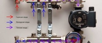
Elevator unit of the heating system
The purpose of this article is to provide an understanding of the structure and operating principle of the elevator itself, its place in the system and the functions it performs. In addition, interested readers will receive a lesson on how to independently calculate this node.
General brief information about heat supply systems
In order to correctly understand the importance of the elevator unit, it is probably necessary to first briefly consider how central heating systems work.
CHP plant with a heating mains system
The source of thermal energy is thermal power plants or boiler houses, in which the coolant is heated to the required temperature through the use of one or another type of fuel (coal, oil products, natural gas, etc.) From there, the coolant is pumped through pipes to points of consumption.
A thermal power plant or a large boiler house is designed to provide heat to a certain area, sometimes covering a very large territory. Pipeline systems turn out to be very long and branched. How to minimize heat losses and distribute it evenly among consumers, so that, for example, the buildings most distant from the thermal power plant do not experience a lack of heat? This is achieved by careful thermal insulation of heating lines and maintaining a certain thermal regime in them.
In practice, several theoretically calculated and practically tested temperature regimes for the operation of boiler houses are used, which ensure heat transfer over significant distances without significant losses, and maximum efficiency and economical operation of boiler equipment. So, for example, modes 150/70, 130/70, 95/70 are used (water temperature in the supply line / return temperature). The choice of a specific mode depends on the climate zone of the region and on the specific level of the current winter air temperature.
Simplified diagram of heat supply from thermal power plant (boiler house) to consumers
1 – Boiler house or thermal power plant.
2 – Consumers of thermal energy.
3 – Heated coolant supply line.
4 – “Return” highway.
5 and 6 – Branches from highways to consumer buildings.
7 – In-house heat distribution units.
From the supply and return mains there are branches to each building connected to this network. But here questions immediately arise.
- Firstly, different objects require different amounts of heat - you cannot compare, for example, a huge residential high-rise and a small low-rise building.
- Secondly, the temperature of the water in the main does not meet the permissible standards for supply directly to the heat exchange devices. As can be seen from the above modes, the temperature very often even exceeds the boiling point, and water is maintained in a liquid aggregate state only due to high pressure and the tightness of the system.
The use of such critical temperatures in heated rooms is unacceptable. And it’s not just a matter of excess thermal energy supply – this is extremely dangerous. Any touch to batteries heated to this level will cause severe tissue burns, and in the event of even a slight depressurization, the coolant instantly turns into hot steam, which can lead to very serious consequences.
The correct choice of heating radiators is extremely important!
Not all heating radiators are the same. It's not only and not so much about the material of manufacture and appearance. They can differ significantly in their performance characteristics and adaptation to a particular heating system.
How to choose the right heating radiators is in a special article on our portal.
Thus, at the local heating unit of the house it is necessary to reduce the temperature and pressure to the calculated operating levels, while ensuring the required heat extraction sufficient for the heating needs of a particular building. This role is performed by special heating equipment. As already mentioned, these can be modern automated complexes, but very often preference is given to a proven elevator unit scheme.
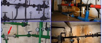
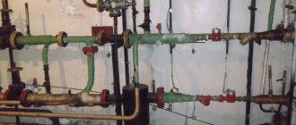
This is what a simple elevator unit in a residential building might look like
If you look at the heat distribution point of a building (most often they are located in the basement, at the entry point of the main heating networks), you will see a node in which a jumper is clearly visible between the supply and return pipes. This is where the elevator itself stands; the structure and principle of operation will be discussed below.
How a heating elevator works and works
Externally, the heating elevator itself is a cast iron or steel structure, equipped with three flanges for insertion into the system.
Elevator appearance
Let's look at its structure inside.
Diagram of the device and operating principle of the jet elevator
Superheated water from the heating main enters the elevator inlet pipe (item 1). Moving forward under pressure, it passes through a narrow nozzle (item 2). A sharp increase in the flow velocity at the nozzle exit leads to an injection effect - a vacuum zone is created in the receiving chamber (item 3). According to the laws of thermodynamics and hydraulics, water is literally “sucked” into this area of low pressure from the pipe (item 4) connected to the “return” pipe. As a result, in the mixing neck of the elevator (item 5), the hot and cooled flows are mixed, the water receives the temperature required for the internal network, the pressure decreases to a level safe for heat exchange devices, and then the coolant through the diffuser (item 6) enters the internal distribution system .
In addition to lowering the temperature, the injector acts as a kind of pump - it creates the required water pressure, which is necessary to ensure its circulation in the intra-house wiring, overcoming the hydraulic resistance of the system.
As you can see, the system is extremely simple, but very effective, which determines its widespread use even in competition with modern high-tech equipment.
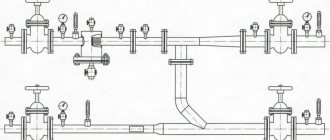
Of course, the elevator needs a certain piping. An approximate diagram of the elevator unit is shown in the diagram:
Basic diagram of the elevator unit piping
Heated water from the heating main enters through the supply pipe (item 1), and returns to it through the return pipe (item 2). The intra-house system can be disconnected from the main pipes using valves (item 3). All assembly of individual parts and devices is carried out using flange connections (item 4).
The control equipment is very sensitive to the purity of the coolant, therefore, mud filters (item 5), direct or “oblique” type, are installed at the inlet and outlet of the system. Solid insoluble inclusions and dirt trapped in the pipe cavity settle in them. The mud ponds are periodically cleaned from collected sediments.
“Mud filters”, direct (from below) and “oblique” type
Control and measuring instruments are installed in certain areas of the unit. These are pressure gauges (item 6) that allow you to control the level of liquid pressure in the pipes. If the pressure at the inlet can reach 12 atmospheres, then at the exit from the elevator unit it is significantly lower, and depends on the number of floors of the building and the number of heat exchange points in it.
There must be temperature sensors - thermometers (item 7) that control the temperature level of the coolant: at the input of their central heating system - t c, at the entrance to the intra-house system - t c, at the “returns” of the system and central – t o c and t c.
Next, the elevator itself is installed (item 8). The rules for its installation require the presence of a straight section of the pipeline of at least 250 mm. With one inlet pipe it is connected through a flange to the supply pipe from the central line, and with the opposite one – to the house distribution pipe (item 11). The lower branch pipe with a flange is connected through a jumper (pos. 9) to the “return” pipe (pos. 12).
To carry out preventive or emergency repair work, valves are provided (item 10), which completely disconnect the elevator unit from the intra-house network. Not shown in the diagram, but in practice there are always special elements for drainage - draining water from the intra-house system when such a need arises.
Of course, the diagram is given in a very simplified form, but it fully reflects the basic structure of the elevator unit. Wide arrows show the directions of coolant flows at different temperature levels.
The undeniable advantages of using an elevator unit to regulate the temperature and pressure of the coolant are:
- Simplicity of design with trouble-free operation.
- Low cost of components and their installation.
- Complete energy independence of such equipment.
- The use of elevator units and heat metering devices makes it possible to achieve savings in the consumption of coolant consumed up to 30%.
There are, of course, very significant disadvantages:
- Each system requires an individual calculation to select the required elevator.
- The need for a mandatory pressure difference at the inlet and outlet.
- Impossibility of precise smooth adjustments with current changes in system parameters.
The last drawback is quite conditional, since in practice elevators are often used, which provide for the possibility of changing its operating characteristics.
Kinematic diagram of an adjustable elevator nozzle
To do this, a special needle is installed in the receiving chamber with a nozzle (item 1) - a cone-shaped rod (item 2), which reduces the cross-section of the nozzle. This rod in the kinematics block (item 3) is connected to the adjusting shaft (item 6) through a rack and pinion gear (item 4 - 5). The rotation of the shaft causes the cone to move in the nozzle cavity, increasing or decreasing the clearance for the passage of liquid. Accordingly, the operating parameters of the entire elevator unit change.
Depending on the level of automation of the system, various types of adjustable elevators can be used.
Elevator with manual nozzle adjustment
Thus, the transmission of rotation can be carried out manually - the responsible specialist monitors the readings of instrumentation and makes adjustments to the operation of the system, focusing on the scale applied near the flywheel (handle).
Adjustment can be carried out automatically, using a servo drive
Another option is when the elevator unit is connected to an electronic monitoring and control system. The readings are taken automatically, the control unit generates signals to transmit them to servos, through which the rotation is transmitted to the kinematic mechanism of the adjustable elevator.
What you need to know about coolants?
In heating systems, especially in autonomous ones, not only water can be used as a coolant.
a coolant for a heating system have , and how to choose it correctly - in a special publication on the portal.
Calculation and selection of heating system elevator
As already mentioned, each building requires a certain amount of thermal energy. This means that a certain calculation of the elevator is necessary, based on the given operating conditions of the system.
The initial data includes:
- Temperature values:
— at the entrance of their heating plant;
— in the “return” of the heating plant;
— operating value for the indoor heating system;
- in the return pipe of the system.
- The total amount of heat required to heat a particular house.
- Parameters characterizing the features of intra-house heating distribution.
The procedure for calculating an elevator is established by a special document - “Code of Rules for the Design of the Ministry of Construction of the Russian Federation”, SP 41-101-95, which relates specifically to the design of heating points. This regulatory manual contains calculation formulas, but they are quite “heavy” and there is no particular need to present them in the article.
Those readers who are little interested in calculation issues can safely skip this section of the article. And for those who want to independently calculate the elevator unit, we can recommend spending 10 ÷ 15 minutes of time to create your own calculator based on the joint venture formulas, which allows you to make accurate calculations in literally a matter of seconds.
Creating a calculator for calculation
To work, you will need the usual Excel application, which probably every user has - it is included in the basic Microsoft Office software package. Creating a calculator will not be particularly difficult even for those users who have never encountered basic programming issues.
Let's look at it step by step:
(if some of the text in the table goes beyond the frame, then there is a “slide” at the bottom for horizontal scrolling)
| Illustration | Brief description of the operation performed |
| Open a new file (workbook) in Excel in Microsoft Office. In cell A1 , type the text “Calculator for calculating the elevator of the heating system.” Below, in cell A2 we type “Initial data”. Inscriptions can be “raised” by changing the boldness, size or color of the font. | |
| Below there will be lines with cells for entering initial data, on the basis of which the elevator will be calculated. Fill in cells A3 to A7 : A3 – “Coolant temperature, degrees C:” A4 – “in the supply pipe of the heating central system” A5 – “in the return pipe of the heating central system” A6 – “required for the intra-house heating system” A7 – “in the return pipe of the system heating" | |
| For clarity, you can skip the line, and below, in cell A9 , enter the text “Required amount of heat for the heating system, kW” | |
| We skip another line and type “Resistance coefficient of the home heating system, m” A11 To prevent text from column A from ending up in column B , where data will be entered in the future, column A can be expanded to the required width (shown by the arrow). | |
| The data entry area, from A2-B2 to A11-B11 , can be selected and filled with color. So it will be different from the other area where the calculation results will be displayed. | |
| We skip one more line and enter in cell A13 “Calculation results:” You can highlight the text in a different color. | |
| Next, the most crucial stage begins. In addition to entering text into the cells of column A , formulas are entered into the adjacent cells of column B , in accordance with which calculations will be carried out. Formulas should be transferred exactly as indicated, without any extra spaces. Important: the formula is entered in the Russian keyboard layout, with the exception of cell names - they are entered exclusively in the Latin layout. In order not to be mistaken with this, in the examples of formulas given, the cell names will be highlighted in bold. So, in cell A14 we type the text “Temperature difference of the heating plant, degrees C.” in cell B14 we enter the following expression =( B4 - B5 ) It is more convenient to enter and control its correctness in the formula bar (green arrow). Don’t be confused by the fact that some value immediately appeared B14 | |
| Fill in the next line. In cell A15 there is the text “Temperature difference of the heating system, degrees C”, and in cell B15 there is the formula =( B6 - B7 ) | |
| Next line. In cell A16 there is the text: “Required performance of the heating system, cubic meters per hour.” Cell B16 should contain the following formula: =(3600* B9 )/(4.19*970* B14 ) An error message will appear, “division by zero” - don’t pay attention, this is simply because the original data has not been entered. | |
| Let's go lower. In cell A17 there is the text: “Elevator mixing coefficient.” Nearby, in cell B17 - the formula: =( B4 - B6 )/( B6 - B7 ) | |
| Next, cell A18 - “Minimum coolant pressure in front of the elevator, m.” Formula in cell B18 : =1.4* B11 *(POWER((1+ B17 );2)) Don’t go astray with the number of parentheses - this is important | |
| Next line. In cell A19 the text: “Elevator neck diameter, mm.” The formula in cell B18 is: =8.5*POWER((POWER( B16 ;2)*POWER(1+ B17 ;2))/ B11 ;0.25) | |
| And the last line of calculations. In cell A20 enter the text “Elevator nozzle diameter, mm.” In cell B20 - formula: =9.6*DEGREE(DEGREE( B16,2 )/ B18,0.25 ) | |
| Basically, the calculator is ready. You can only modernize it a little so that it is more convenient to use, and there is no risk of accidentally deleting the formula. To begin with, select the area from A13-B13 to A20-B20 , and fill it with a different color. The fill button is shown with an arrow. | |
| Now we select the general area from A2-B2 to A20-B20 . In the “borders” (shown by an arrow), select “all borders” . Our table receives a harmonious frame with lines. | |
| Now we need to make sure that values can be manually entered only into those cells that are intended for this (so as not to erase or accidentally break formulas). Select the range of cells from B4 to B11 (red arrows). Go to the “format” (green arrow) and select “cell format” (blue arrow). | |
| In the window that opens, select the last tab – “protection” and uncheck the “protected cell” box. | |
| Now again go to the “format” , and select the “protect sheet” . | |
| A small window will appear in which all you have to do is click “OK” . We simply ignore the prompt to enter a password - our document does not need such a degree of protection. Now you can be sure that there will be no failure - only the cells in column B in the value entry area are open for changes. If you try to add anything to any other cells, a window will appear warning you that such an operation is impossible. | |
| The calculator is ready. All that remains is to save the file. – and he will always be ready to carry out calculations. |
Carrying out calculations in the created application is not difficult. You just need to fill the input area with known values - then the program will calculate everything automatically.
- The supply and return temperatures in the heating plant can be found in the heating station (boiler room) closest to the house.
- The required temperature of the coolant in the intra-house system largely depends on what heat exchange devices are installed in the apartments.
- The temperature in the “return” pipe of the system is most often assumed to be equal to the same indicator in the central line.
- The house’s need for a general influx of thermal energy depends on the number of apartments, heat exchange points (radiators), the characteristics of the building - the degree of its insulation, the volume of premises, the amount of total heat loss, etc. Typically, these data are calculated in advance at the design stage of a house or during the reconstruction of its heating system.
- The resistance coefficient of the internal heating circuit of a house is calculated using separate formulas, taking into account the characteristics of the system. However, it would not be a big mistake to take the average values given in the table below:
| Types of multi-apartment residential buildings | Coefficient value, m |
| Apartment buildings of old construction, with heating circuits made of steel pipes, without temperature and coolant flow regulators on risers and radiators. | 1 |
| Houses put into operation or in which major repairs were carried out before 2012, with the installation of polypropylene pipes on the heating system, without temperature and coolant flow regulators on risers and radiators | 3 ÷ 4 |
| Houses put into operation or after major renovations after 2012, with the installation of polypropylene pipes on the heating system, without temperature and coolant flow regulators on risers and radiators. | 2 |
| The same thing, but with installed temperature and coolant flow control devices on risers and radiators | 4 ÷ 6 |
Carrying out calculations and selecting the desired elevator model
Let's try the calculator in action.
Let’s assume that the temperature in the supply pipe of the heating plant is 135, and in the return pipe – 70 °C. It is planned to maintain a temperature of 85 °C in the heating system of the house, and 70 °C at the outlet. For high-quality heating of all rooms, a thermal power of 80 kW is required. According to the table, it is determined that the resistance coefficient is “1”.
We substitute these values into the corresponding lines of the calculator, and immediately get the necessary results:
After entering the initial data, we immediately get the finished result
As a result, we have the data for selecting the required elevator model and the conditions for its correct operation. Thus, the required system performance was obtained - the amount of coolant pumped per unit time, the minimum pressure of the water column. And the most basic quantities are the diameters of the elevator nozzle and its neck (mixing chamber).
The nozzle diameter is usually rounded down to hundredths of a millimeter (in this case, 4.4 mm). The minimum diameter value should be 3 mm - otherwise the nozzle will simply clog quickly.
The calculator allows you to “play” with the values, that is, see how they will change when the initial parameters change. For example, if the temperature in a heating plant is reduced, say, to 110 degrees, then this will affect other parameters of the unit.
Changing any initial parameter immediately changes the calculation results
As you can see, the diameter of the elevator nozzle is already 7.2 mm.
This makes it possible to select a device with the most acceptable parameters, with a certain range of adjustments, or a set of replacement nozzles for a specific model.
Having the calculated data, you can already refer to the tables of manufacturers of such equipment to select the required version.
Typically, in these tables, in addition to the calculated values, other parameters of the product are given - its dimensions, flange sizes, weight, etc.
For example, water-jet steel elevators of the 40s10bk series:
Basic linear parameters of a jet elevator
Flanges: 1 – at the inlet, 1-1 – at the pipe insertion from the “return”, 1-2 – at the outlet.
2 – inlet pipe.
3 – removable nozzle.
4 – receiving chamber.
5 – mixing neck.
7 – diffuser.
The main parameters are summarized in the table for ease of selection:
| Elevator number | Dimensions, mm | Weight, kg | Approximate water consumption from the network, t/h | |||||||
| dc | dg | D | D1 | D2 | l | L1 | L | |||
| 1 | 3 | 15 | 110 | 125 | 125 | 90 | 110 | 425 | 9,1 | 0,5-1 |
| 2 | 4 | 20 | 110 | 125 | 125 | 90 | 110 | 425 | 9,5 | 1-2 |
| 3 | 5 | 25 | 125 | 160 | 160 | 135 | 155 | 626 | 16,0 | 1-3 |
| 4 | 5 | 30 | 125 | 160 | 160 | 135 | 155 | 626 | 15,0 | 3-5 |
| 5 | 5 | 35 | 125 | 160 | 160 | 135 | 155 | 626 | 14,5 | 5-10 |
| 6 | 10 | 47 | 160 | 180 | 180 | 180 | 175 | 720 | 25 | 10-15 |
| 7 | 10 | 59 | 160 | 180 | 180 | 180 | 175 | 720 | 34 | 15-25 |
In this case, the manufacturer allows you to independently replace the nozzle with the required diameter within a certain range:
| Elevator model, no. | Possible range of nozzle change, Ø mm |
| №1 | min 3 mm, max 6 mm |
| №2 | min 4 mm, max 9 mm |
| №3 | min 6 mm, max 10 mm |
| №4 | min 7 mm, max 12 mm |
| №5 | min 9 mm, max 14 mm |
| №6 | min 10 mm, max 18 mm |
| №7 | min 21 mm, max 25 mm |
Selecting the required model, having the calculation results in hand, will not be difficult.
When installing an elevator or carrying out preventive maintenance, it is necessary to take into account that the efficiency of the unit directly depends on the correct installation and integrity of the parts.
Thus, the nozzle cone (glass) must be installed strictly coaxially with the mixing chamber (neck). The glass itself must fit freely into the elevator seat so that it can be removed for inspection or replacement.
When carrying out inspections, special attention should be paid to the condition of the surfaces of the elevator sections. Even the presence of filters does not exclude the abrasive effect of the liquid, plus there is no escape from erosion processes and corrosion. The working cone itself must have a polished inner surface and smooth, unworn edges of the nozzle. If necessary, it is replaced with a new part.
Elevator nozzles require periodic inspection and replacement
Failure to comply with such requirements entails a decrease in the efficiency of the unit and a drop in the pressure required for the circulation of the coolant in the intra-house heating distribution. In addition, wear of the nozzle, its contamination or too large a diameter (significantly higher than the calculated one) will lead to the appearance of strong hydraulic noise, which will be transmitted through the heating pipes to the living quarters of the building.
Elevator unit with automatic adjustment
Of course, a home heating system with a simple elevator unit is far from being an example of perfection. It is very difficult to adjust, which requires disassembling the unit and replacing the injection nozzle. Therefore, the best option seems to be modernization with the installation of adjustable elevators, which allow changing the coolant mixing parameters within a certain range.
How to regulate the temperature in the apartment?
The temperature of the coolant in the intra-house network may be excessive for a single apartment, for example, if it uses “warm floors”. This means that you will need to install your own equipment, which will help maintain the degree of heating at the desired level.
Options for how to connect heated floors to heating are in a special article on our portal.
And finally, a video with computer visualization of the device and operating principle of the heating elevator:
Video: design and operation of a heating elevator
Heating elevator calculation
It should be noted that the calculation of a water jet pump, which is an elevator, is considered quite cumbersome; we will try to present it in an accessible form. So, to select a unit, two main characteristics of elevators are important to us - the internal size of the mixing chamber and the bore diameter of the nozzle. The chamber size is determined by the formula:
- dr – required diameter, cm;
- Gpr – reduced amount of mixed water, t/h.
In turn, the reduced flow rate is calculated as follows:
In this formula:
- τcm – temperature of the mixture used for heating, °C;
- τ20 – temperature of the cooled coolant in the return, °C;
- h2 – resistance of the heating system, m. water. Art.;
- Q – required heat consumption, kcal/h.
To select the elevator unit of the heating system according to the size of the nozzle, it is necessary to calculate it using the formula:
- dr – diameter of the mixing chamber, cm;
- Gpr – reduced consumption of mixed water, t/h;
- u is the dimensionless injection (mixing) coefficient.
The first 2 parameters are already known, all that remains is to find the value of the mixing coefficient:
In this formula:
- τ1 – temperature of the superheated coolant at the entrance to the elevator;
- τcm, τ20 – the same as in the previous formulas.
Based on the results obtained, the unit is selected according to two main characteristics. The standard sizes of elevators are designated by numbers from 1 to 7; you need to take the one that is closest to the design parameters.
Calculation and selection of elevator by number
Let’s immediately clarify the procedure: first of all, the diameter of the mixing chamber is calculated and the appropriate elevator number is selected, then the size of the working nozzle is determined. The diameter of the injection chamber (in centimeters) is calculated by the formula:
The indicator Gpr participating in the formula is the real coolant flow rate in the system of an apartment building, taking into account its hydraulic resistance. The value is calculated as follows:
- Q – amount of heat consumed to heat the building, kcal/h;
- Tcm is the temperature of the mixture at the outlet of the elevator tee;
- Т2о – water temperature in the return line;
- h is the resistance of the entire heating wiring together with radiators, expressed in meters of water column.
Reference. To insert unknown kilocalories into the formula, you need to multiply the familiar watts by a factor of 0.86. Meters of water column are converted to the more common units: 10.2 m water. Art. = 1 Bar.
An example of selecting an elevator number. We found out that the actual consumption Gpr will be 10 tons of mixed water in 1 hour. Then the diameter of the mixing chamber is 0.874 √10 = 2.76 cm. It is logical to take mixer No. 4 with a 30 mm chamber.
Now we find out the diameter of the narrow part of the nozzle (in millimeters) using the following formula:
- Dr – previously determined size of the injection chamber, cm;
- u – mixing coefficient;
- Gpr is our consumption of the finished coolant when supplied to the system.
Although the formula seems cumbersome on the surface, in reality the calculations are not too complicated. One parameter remains unknown - the injection coefficient, calculated as follows:
We have deciphered all the designations from this formula, except for parameter T1 - the temperature of hot water at the entrance to the elevator. If we assume that its value is 150 degrees, and the supply and return temperatures are 90 and 70 °C, respectively, the required size Dc will be 8.5 mm (at a flow rate of 10 t/h of water).
When the pressure value Нр at the entrance to the elevator from the central side is known, you can use an alternative formula for determining the diameter:
Comment. The result of the calculation using the last formula is expressed in centimeters.