A heat exchanger is a simple piece of equipment that is often included in the circuit of various types of industrial devices. In some cases, plate heat exchangers are used in domestic air conditioning and refrigeration systems. As the name implies, these devices are designed to select thermal energy from one medium and transfer it to another.
Plate heat exchanger is used for heating or cooling various processes
Design Features
The main purpose of any type of plastic heat exchanger is to convert heated liquid into a cooled environment. The design of the plate heat exchanger has collapsible parts, and the device consists of the following elements:
- set of plates;
- movable and fixed plates;
- rounded upper and lower guides;
- fastening elements that combine the slabs into a common frame.
Frame sizes of different products can vary significantly. They will depend on the heat transfer and power of the heater - with a large number of plates, the productivity of the equipment increases and, naturally, the weight and dimensions increase.
You can control the power on the heat exchanger - increase or decrease
Advantages of plate devices:
- low production and investment costs;
- highly efficient heat transfer;
- small dimensions;
- self-cleaning effect using high turbulent flow;
- the ability to increase efficiency by adding plates;
- high degree of reliability;
- ease of washing;
- small weight;
- ease of installation;
- minimal surface contamination;
- impossibility of mixing liquids due to a special seal configuration;
- high corrosion resistance;
- minimal heat transfer surface due to high efficiency;
- insignificant pressure losses due to the optimal choice of plates with different types of profiles;
- effective temperature regulation due to the small volume of coolant.
In this video you will learn how hot water is generated thanks to a heat exchanger:
Collapsible plate types
Advantages
- minimum production costs
- minimum installation cost
- performance is adjustable
- ease of operation and repair
- low operating costs
- downtime is minimal
- low energy consumption
Application
- heating systems
- residential buildings and premises
- swimming pools
- refrigeration and climate control units
- hot water supply systems
- heating points
Plate arrangement
The design and operating principle of a plate heat exchanger will depend on the modification of the equipment, which may contain a different number of plates with fixed gaskets. These gaskets block the channels with the passing coolant. To achieve the required tightness of the fit of pairs of interconnected gaskets, it is sufficient to fasten these plates with a movable plate.
The loads that act on this device are distributed, as a rule, onto the plates and seals. The frame and fastening elements, by and large, constitute the body of the equipment.
The relief surface of the plates during compression guarantees a strong fastening and allows the entire heat exchanger system to gain the necessary strength and rigidity.
The gaskets are fixed to the plates using a clip connection. It must be said that the gaskets are self-centered relative to their axis during clamping. Leakage of the thermal fluid is prevented thanks to the edging of the cuff, which additionally creates a barrier.
For the installation of a plate heat exchanger, several types of seals are manufactured: with hard and soft corrugation.
More information about heat exchange equipment:
In soft plates, the channels are at an angle of 30 degrees. This type of device is characterized by high thermal conductivity, but low resistance to coolant pressure.
In rigid elements, when making grooves, an angle of 60 degrees is made. These devices are not characterized by increased thermal conductivity; their main advantage is the ability to withstand significant coolant pressure.
To achieve the best thermal efficiency, you can combine plates. Moreover, it must be taken into account that for optimal operation of the device, it is necessary that it operate in turbulence mode - the coolant must move through the channels without any delays. By the way, a shell-and-tube heat exchanger, where the design has a “pipe-in-pipe” design, has a laminar coolant flow.
What is the advantage? While maintaining the same thermal characteristics, plate equipment has significantly smaller dimensions.
Requirements for gaskets
Devices with plates are subject to rather stringent requirements regarding the tightness of the equipment; it is for this reason that today gaskets have begun to be made from polymers. For example, ethylene propylene can easily be used at elevated temperatures - both steam and liquid. However, it begins to deteriorate quite quickly in an environment that contains large amounts of fats and acids.
Heat exchangers differ in the number of plates
The seals are attached to the plates most often using clip locks, and in rare cases - using an adhesive.
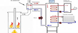
Principle of operation
If we consider how a plate heat exchanger works, its operating principle cannot be called very simple. The plates are turned to each other at an angle of 180 degrees. Most often, one package contains two pairs of plates, which create 2 collector circuits: inlet and outlet of the coolant. Moreover, it must be taken into account that the steam located at the edge is not involved during heat exchange.
Today, several different types of heat exchangers are manufactured, which, depending on the operating mechanism and design, are divided into:
- two-way;
- multi-circuit;
- single-circuit.
The operating principle of a single-circuit device is as follows. The coolant circulates in the device throughout the entire circuit permanently in one direction. In addition, a counterflow of heat carriers is also produced.
Multi-circuit devices are used only when there is a slight difference between the temperature of the return and incoming coolant. In this case, the water moves in different directions.
More details about plate heat exchanger:
Two-way devices have two independent circuits. With the condition of constant adjustment of the heat supply, the use of these devices is most appropriate.
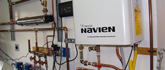
Joint connection of two boilers
To increase the heating comfort of a private home, many owners install two or more heat sources that run on different energy sources. At the moment, the most relevant combinations of boilers are:
- natural gas and wood;
- solid fuel and electricity.
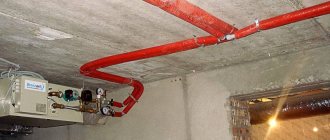
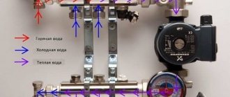
Accordingly, the gas and solid fuel boiler must be connected in such a way that the second automatically replaces the first after burning the next portion of firewood. The same requirements are put forward for connecting an electric boiler to a wood boiler. This is quite simple to do when a buffer tank is involved in the piping scheme, since it simultaneously plays the role of a hydraulic arrow, as shown in the figure.
As you can see, thanks to the presence of an intermediate storage tank, 2 different boilers can serve several heating distribution circuits at once - radiators and heated floors, and in addition load an indirect heating boiler. But not everyone installs a heat accumulator with a TT boiler, since this is not a cheap pleasure. In this case, there is a simple diagram, and you can install it yourself:
Note. The scheme is valid for both electric and gas heat generators operating together with solid fuel.
Here the main source of heat is a wood heater. After a stack of firewood burns out, the air temperature in the house begins to drop, which is registered by the room thermostat sensor and immediately turns on heating by the electric boiler. Without a new load of firewood, the temperature in the supply pipe decreases and the overhead mechanical thermostat turns off the pump of the solid fuel unit. If you ignite it after some time, everything will happen in the reverse order. This video is described in detail about this joint connection method:
Tying using the method of primary and secondary rings
There is another way to combine a solid fuel boiler with an electric one to supply a large number of consumers. This is a method of primary and secondary circulation rings, which provides for hydraulic separation of flows, but without the use of a hydraulic needle. Also, for reliable operation of the system, a minimum of electronics is required, and a controller is not needed at all, despite the apparent complexity of the circuit:
The trick is that all consumers and boilers are connected to one primary circulation ring by both the supply and return pipelines. Due to the small distance between connections (up to 300 mm), the pressure drop is minimal compared to the pressure of the main circuit pump. Due to this, the movement of water in the primary ring does not depend on the operation of the secondary ring pumps. Only the temperature of the coolant changes.
Theoretically, any number of heat sources and secondary rings can be included in the main circuit. The main thing is to choose the right pipe diameters and the performance of the pumping units. The actual performance of the main ring pump must exceed the flow rate in the most “gluttonous” secondary circuit.
To achieve this, it is necessary to perform a hydraulic calculation and only then will it be possible to select the right pumps, so an ordinary homeowner cannot do without the help of specialists. In addition, it is necessary to link the operation of solid fuel and electric boilers by installing shut-off thermostats, as described in the following video:
Area of use
Today there are several types of heat exchangers.
Moreover, each of the devices has a unique design and operating feature:
- soldered;
- collapsible;
- semi-welded;
- welded
Devices with a collapsible system are often used in heating networks that are connected to residential buildings and buildings for various purposes, in climate systems and refrigerators, swimming pools, heating stations and hot water supply circuits. Soldered devices have found their purpose in freezing units, ventilation networks, air conditioning devices, industrial equipment for various purposes, and compressors.
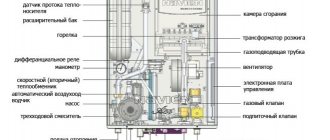
Detailed design of a plate heat exchanger
Semi-welded and welded heat exchangers are used in:
- ventilation and climate systems;
- pharmaceutical and chemical field;
- circulation pumps;
- food sector;
- recovery systems;
- devices for cooling devices for various purposes;
- in heating circuits and DHW.
The most popular type of heat exchanger, which is used in everyday life, is soldered, which provides heating or cooling of the coolant.
Heat exchanger piping
As a rule, the installation of such thermal power equipment is provided for in individual boiler houses of multi-apartment residential buildings or industrial enterprises, as well as in heating points of centralized heat supply systems. The goal is to obtain water for domestic hot water needs at a temperature of up to 70 ºС or a coolant up to 95 ºС when using steam and high-temperature hot water boilers.
Due to its small dimensions and weight, installation of the heat exchanger is quite simple, although powerful units require a foundation. In any case, the foundation bolts are poured, with the help of which the device is securely fixed in its place. The coolant is always supplied to the upper branch pipe, and the return pipeline is connected to the fitting located below it. The heated water supply is connected, on the contrary, to the lower pipe, and its outlet to the upper one. The simplest wiring diagram for a plate heat exchanger is shown below:
The coolant supply circuit must have its own circulation pump installed on the supply pipeline. In accordance with the rules, in addition to the working pump, a reserve pump of the same power is installed in parallel. If the DHW system has a return circulation line, then the connection diagram takes the following form:
Here, the heat of water flowing through a closed DHW circuit is used, cold water from the water supply is mixed with it, and only then the mixture enters the heat exchanger. The outlet temperature is controlled by an electronic unit that controls the valve on the coolant supply line. Well, the last scheme is a two-stage one, which allows you to use the thermal energy of the return line of the heating system:
The scheme allows you to save significantly by removing excess load from boilers and using the available heat to the maximum. It should be noted that in all schemes filters are installed at the entrance to the high-speed heat exchanger. The reliable and durable operation of the unit depends on this.
Characteristics and calculation
Plates and seals as the main parts of heat exchange devices are made from materials that differ in their performance and characteristics. When choosing a particular product, the main role is played by its purpose and scope of application.
If we consider heating systems and hot water supply, then in this area, plates that are made of stainless steel and plastic seals made of special rubber NBR or EPDM are most often used. The presence of stainless steel plates makes it possible to work with a coolant heated to 120 degrees; in another case, the heat exchanger can heat the liquid up to 180°C.
Gaskets are located between the plates for sealing
When using heat exchangers in the industrial sector and connecting them to technological processes exposed to oils, acids, fats, alkalis and other aggressive media, plates made of titanium, bronze and other metals are used. In these cases, the installation of asbestos or fluorine rubber gaskets is required.
The choice of heat exchanger is carried out taking into account calculations that are made using special software.
During calculations it is necessary to take into account:
- consumption of heated liquid;
- initial temperature of the coolant;
- heating fluid costs;
- required heating temperature.
The heating medium that flows through the heat exchanger can be heated water to a temperature of 90-120°C or steam with a temperature of up to 170°C. The type of coolant is selected taking into account the type of boiler equipment used. The dimensions and number of plates are selected so as to produce a coolant with a temperature that complies with current standards - no higher than 65°C.
The heat exchanger can be made of different types of metal
It must be said that the main technical characteristics, which are also considered the main advantages, are the compact dimensions of the equipment and the ability to provide a fairly significant flow rate.
The range of exchange areas and probable costs for the devices is quite high. The smallest of them, for example, from Alfa Laval, have a surface size of up to 1 m² and at the same time provide the passage of a coolant amount of up to 0.3 m³/hour. The largest devices have a size of about 2500 m² and a flow rate that exceeds 4000 m³/hour.