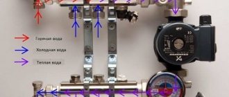
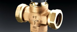
Three-way thermostatic mixing valve is a device for maintaining a stable water temperature by regulating the cold and hot inlet flows. There are valves on sale with different operating principles, but most often the role of a regulator is played by a bimetallic element that deforms when the temperature changes. The thermostatic mixing valve can also be controlled by an electric servomotor. Such devices have much greater throughput and response speed, but their price is higher.
Varieties and purpose of each type
Three-way valves are mainly divided according to their operating principle. There are three positions here:
- mixing,
- dividing,
- switchable.
The designations on the body show what type of devices they belong to.
The former mix two coolant flows with different temperatures into one, while the latter, on the contrary, divide one flow into two. And still others simply switch the movement of water from one direction (circuit) to another. The first two varieties are similar in appearance to each other, so a diagram is applied to their body, which shows for what purpose the device should be used.
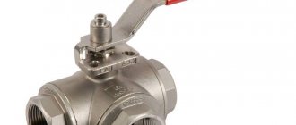
As for the third position, it is easy to distinguish it from the rest. It additionally has a block with the help of which switching occurs. A valve of this type is usually installed in a dual-circuit heating system when it is necessary to redirect the coolant flow from the heating system to the boiler and vice versa.
Switching type valve
Related article:
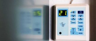
Thermostats with air temperature sensor. A separate material provides practical guidance on the selection and installation of thermostats.
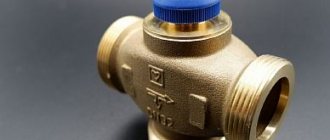
In what cases is it permissible to use a simplified valve?
In fairly simple heating communications that operate on solid fuel, it is allowed to use simplified versions of three-way valves. As a rule, such products operate autonomously. In most cases, they do not require a thermal head and stem to function.
The operating principle of a simplified type three-way valve is quite simple. The element that regulates the operation of such a device is located inside its body. Such valves are adjusted to a certain water temperature and are obtained by mixing streams with different temperatures. The temperature that such a product supports is usually indicated on its body.
The constant outlet temperature maintained by this simplified version of the valve is constant. Let's consider the advantages and disadvantages of using such a device:
- plus - a more affordable price compared to a product that is equipped with a thermal head. The savings in this case are at least 30%;
- minus - the impossibility of adjusting the outlet water temperature.
Before purchasing a thermostatic three-way simplified mixing valve, experts recommend studying the technical documentation that regulates the solid fuel heating apparatus. This is due to the fact that there you can find the required minimum temperature that the return coolant must meet.
The design and principle of operation of a three-way valve in a heating system
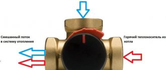
So, first of all, let's look at the device. To make it easier to understand what’s inside the valve, you need to look at the photo below, which shows the device in cross-section. It consists of three pipes (two side, one bottom), between which the mixing chamber is located. On the fourth side (top) there is a thermal head responsible for controlling the temperature of the coolant.
Sectional view of a three-way valve
Inside the device, from the thermostat there is a spring-loaded rod with two flat round valves. Their diameter corresponds to the diameter of the nozzle seats. Instead, one ball valve can be installed, located inside the mixing chamber between two seats. When there is pressure on the rod, the valves partially block the flow from the lower pipe and open the upper one. The same thing only happens the other way around if the rod rises up.
But here you need to figure out what laws the rod works by, under what force it lowers or rises. It's all about the thermal head itself. Inside it is a temperature sensor filled with a special liquid. She is heat sensitive. As soon as the temperature of the coolant begins to rise, the liquid expands and rises through the capillary tube into a special bellows (container), which is located in the thermal head. The reservoir itself begins to expand, which puts pressure on the rod. The latter lowers and opens the lower pipe, from where cold water flows into the three-way valve. Hot water comes from the left pipe (see photo).
Separating and mixing valves
Of course, pressure simply cannot happen with any increase in water temperature. To do this, a temperature gradation is installed on the thermal head, which is adjusted manually. It is the set parameter that is the moment of pressing the rod.
So, the rod reacted to the change in the temperature of the coolant in the supply pipe, opened the lower one for cold water, and inside the valve the hot and cold media were mixed to the required temperature. That is, it turns out that the temperature of the coolant at the inlet has not changed, but at the outlet it has become lower.
If the coolant continues to heat up, the rod can drop to the lowest possible position. That is, it will completely close the hot water supply and completely open the cold water supply. And this will continue until the coolant inside the heating system drops to the required temperature. After which the top valve will open, it will release hot water.
Scheme of mixing coolant with return
This is how a three-way mixing control valve works. As for the separation model, its operating principle is almost the same, only in reverse. The coolant enters one pipe; inside the device body it is divided into two streams and exits through two adjacent pipes.
This type of shut-off valve is installed in those areas where the coolant flow needs to be divided into two circuits. One of them will have a constant thermal regime, the other will have a variable one. The first is the fluid flow, which has quality requirements. The second with quantity requirements. In this case, purely structurally, the flow with a constant hydraulic regime is never blocked, because in the design of the device, the length of the rod is made in such a way that the valve does not close the constant circuit.
But it is necessary to indicate that the length of the rod can be adjusted. This makes it possible to adjust the required volume of coolant on a constant circuit. As for the variable, it can completely overlap. This is how the flow and pressure of the coolant in the heating system is regulated. As you can see, the operating principle of a three-way valve is quite simple. The main thing is to accurately select the type of device and install it in the required location in the circuit.
How does a three-way thermostatic valve work in a heated floor system?
To make it clear how the circuit with the valve works, we can give an example of coolant circulation in a heated floor system. The three-way valve for underfloor heating is a mixing valve. The circulation scheme here is as follows:
- hot water enters the underfloor heating system through the collector;
- it must have a certain temperature, which is monitored precisely as it passes through the three-way valve;
- as soon as its value exceeds the permissible value, the valve opens one of the circuits, which is connected to the heating return;
- cooled coolant enters inside, lowering the temperature,
- after which the mixed water enters the heating circuit of the heated floor;
- as soon as the temperature drops to the required value, the return circuit inside the valve is closed with a rod.
Piping for underfloor heating with a three-way valve
Operational scope of three-way mixing devices
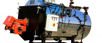
Today, three-way thermostatic mixing valves are widely used in heating pipes. They are especially recommended for use in heating systems that operate on solid fuel. In addition, in domestic conditions such valves are necessary in order to regulate the elevated temperature in the pipeline transporting hot water. The temperature in this case can reach up to +95 °C, which is a high indicator.
Note! Installing such devices in front of plastic pipelines transporting hot water eliminates the possibility of overheating of the polymer material.
Let's look at the main functions that such mixing valves perform:
- distribution of flows coming from different pipeline lines;
- ensuring normal temperature of the working medium at the outlet. This occurs by mixing hot and cold flows;
- Using a three-way mixing device, you can adjust the water temperature at different periods of time, which is very convenient.
It is recommended to install a thermostatic valve in the hot water supply system.
Such a device must be installed in heating communications and hot water supply systems. As a rule, such valves are installed in apartments and private houses with autonomous heating.
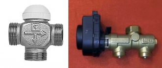
Three-way valves with actuators
Experts say that adjusting a three-way valve using a thermal head and sensor is the simplest and most accurate. In addition, there is no energy consumption. This is why this type of three-way valve is popular today. But you can control the process in other ways. The simplest one is manual. Let's face it, it's not the most accurate option, because the range of the rod's immersion depth is set by a handle located outside the valve body.
Attention! A valve with such an adjustment is recommended to be used only in those heating systems where the temperature differences of the coolant are insignificant.
The second option is temperature control using electric drives. They receive commands from the controller.
Three-way valve with drive
Motorized 3-way valve
Motors mounted on valves are often called servos. In fact, these are ordinary electric motors in which the shaft does not rotate, but rotates by a certain degree. It should be noted that this category includes any types of engines, for example, thermal ones. The main thing is to fulfill the condition of rotation, not rotation.
Manufacturers today offer two items regarding configuration. The first is a complete package that includes a controller and temperature sensor. It is possible to immediately adjust the device to the required temperature, as well as to the rotation angle, for example, from 0 to 180°. In this case, any intermediate values are possible. The second is a separate drive with a sensor inside, to which you need to add a controller as a separate element.
Cast iron fittings with servo drive for large heating networks
As for the controller, it is a device that solves problems of signal management. In the case of heating, it reacts to temperature changes that are signaled to it by a temperature sensor. It processes the signals and decides what to do - open the valve or close it, or rather, turn it clockwise or counterclockwise. Today, manufacturers offer a huge model line of three-way valves with electric drives. One of the most popular brands is “ESBE” (Sweden).
Electrically actuated 3-way valve ESBE
First of all, it should be noted that this brand of valve has a ball inside with through slots. The latter open or close two channels, the third always remains open. Through it, coolant enters the heating system. Rotation degree – 90÷180°.
ESBE from a Swedish manufacturer
In stores, the valve of this model is sold separately from the servo drive, so before installation they are connected to each other by inserting the actuator axis (shaft) into the upper part of the rod. There is a hole in it for the axle. After that, you need to carry out adjustments in terms of temperature conditions exactly according to the instructions included with the device.
Today, the manufacturer offers a fairly wide range of ESBE three-way valves with and without a drive:
| Photo | Model | Purpose |
| VTA 200 | Designed for systems where there is no water recirculation. | |
| VTA 270 | This is a thermo-mixing valve for underfloor heating. It is installed if heating is organized in a room with an area of at least 100 m² | |
| VTA 310 | Valve for general use in any heating systems where the coolant temperature does not exceed +95°C and the pressure is 0.3 atm. | |
| VTA 300/ VTA 360 | The two models differ from each other only in the direction of movement of water in the heating system. The temperature is well controlled even during pressure surges within the network. | |
| VTC300 | This is a three-way valve without servomotor. It can be installed in systems that use low-power boilers - up to 30 kW. | |
| DN25 | This is a three-way valve for solid fuel boilers. That is, it can withstand coolant temperatures up to +110°C. In this case, the boiler power should not be less than 150 kW. This is one of the most unpretentious devices on the market. It can work under any conditions in any heating networks without changing quality. | |
| VRG131 | This is the most popular and in demand device, which is used in apartments and private houses. |
Other models of three-way valves
Another well-known brand is the Navien three-way valve from a South Korean company. It should be noted that this device is an integral part of the double-circuit boiler of this manufacturer. And it is installed inside the heating equipment. Its main purpose is to separate the coolant into the heating network and the hot water supply.
Attention! Navien valves cannot be repaired. The main cause of failure is the gear transmission from the motor to the rod. Spare parts are not sold anywhere. If the device fails, it must be replaced with a new one.
Three way valve Navien
The Danish company Danfoss is a well-known manufacturer of three-way valves. It offers four models that are designed for different systems:
| Photo | Model | Purpose |
| VF3 | Used in air conditioning and heating systems. Manufacturing material – cast iron. With flange connection. | |
| VMV | For use in heating systems only. Material of manufacture: bronze or stainless steel. | |
| VRB3 | This is a mixer that is used in both heating systems and refrigeration systems. Material – stainless steel. | |
| VRG3 | Installed in heating networks or when transporting refrigerant. The material is either stainless steel or cast iron. |
For many novice plumbers, the three-way valve is fraught with many mysteries and mysteries. In this article I will try to explain how a three-way servo valve will work in three different models. We will look at the logic of operation and the electrical circuit for connecting servos.
Option 1:
Price from 6300 to 9200 rubles. There may be variants of articles.
Option 2:
The price is about 2500-5000 rubles, if you try to find it on a Chinese website and order it from China.
Option 3.
An expensive option, but there are a lot of options. The price can be about 15-20 thousand rubles.
Connection diagram of a three-way valve with a servomotor for domestic hot water supply
The valve can be installed both on the supply line (supply) and on the return line of the pipeline (return).
Many will ask the question:
- Where is it better? For supply or return?
In terms of DHW functionality, this is not important. But there are some nuances why it is necessary to put it on supply or return.
Nuances between supply and return:
1.
A three-way valve is placed on the supply side to relieve the return pipeline line of any valves that may block the passage of the coolant. Simply put, to drain water from the heating system. Also helps when starting the heating system. Filling the system with water and releasing air occurs better. The three-way valve on the return line will interfere with the filling and draining of water from the heating system.
2.
Also, a three-way DHW valve is placed on the supply side in order to obtain the correct distribution of hydraulic resistance relative to the pump on the pump line. Expressed in a difficult way, of course. But if you start studying how pressure is distributed at each point in the heating system, you will understand the difference in how different valves affect pressure distribution. This effect will be stronger the larger the loss occurs at the valve. Simply put, a low critical pressure may appear at some point in the system. And low pressure can cause cavitation in pumps and not only in pumps.
3.
At very high temperatures (90-110) the three-way valve can be installed on the return line. This mainly needs to be done where there are solid fuel boilers. Where there is no protection from high temperature. High temperatures lead to leakage of the valves.
Anyone
Do any of you know why it is necessary to install a hydraulic accumulator on the return line of the pump?
Or does he think it can be placed anywhere? Do you know why the pump is installed on supply or return? Answer:
This is because the pressure distribution at different points in the pipeline changes depending on where these elements are located. And in some cases, the reason again becomes the convenience of filling and draining coolant in the heating system. It also helps to avoid airing and much more.
And why
Does the boiler equipment manual recommend keeping the pressure at least 1.5 Bar? Because the pressure in the boiler heat exchanger cannot be reduced! A decrease in pressure leads to cavitation of the coolant in the heat exchanger. It also leads to early boiling of the coolant. And all this leads not only to a decrease in boiler power, but also to the deposition of scale in the heat exchangers, which leads to scale deposition and overgrowth of the heat exchangers. Which in turn will lead to a short service life of the boiler equipment.
Do you think
, if the pressure gauge shows 1.5 Bar, this means that pressure less than 1.5 Bar cannot be present in the system at the same height. Where is the pressure gauge?
Answer:
This can happen, and more often it happens to owners who independently figure out where the pump and hydraulic accumulator will be located. And they don’t understand how the pressure will be distributed after that.
You can learn more about the distribution of hydraulic resistance here: https://infobos.ru/str/601.html
Also how does a hydraulic accumulator affect pressure distribution: https://santeh-baza.ru/viewtopic.php?f=2&t=93
Why do you need a three-way valve for domestic hot water?
The main task of a three-way valve for domestic hot water is to redirect the movement of coolant from the heating system towards the indirect heating boiler (another heat exchanger) and back automatically.
As soon as the command comes to heat the indirect heating boiler, you need to redirect the coolant towards the BKN coil. The heating signal is generated by a special relay, which is located at the BKN (Indirect Heating Boiler). That is, the BKN has a built-in electric thermal relay, which provides a switching contact.
Schemes of operation of boilers with three-way valves for producing hot water
What is an indirect heating boiler?
What does a three-way valve for domestic hot water look like?
The valve itself can have a variety of shapes. The valve may have a moving stem. There may also be a valve with a rotating mechanism.
Option 1 and Option 2
- These are valves with a moving stem.
Option 1.
Suitable for a private home for up to 8 people and 4 bathrooms. This is a certain strict valve standard and is not subject to different capacity options. Simply because such a valve is often located inside a wall-mounted boiler. And it often has its own specific diameter and capacity. Unfortunately, I couldn't find its bandwidth.
Option 2.
There can be many options in terms of throughput and choice of diameters.
Option 3.
A valve with a rotating mechanism is called
a rotary mixing valve
. A rotary mixing valve can be used not only for mixing, but also to simply redirect the coolant flow to another pipeline.
Option 3
Designed mainly for high flow valves. It has the ability to use valves with a large diameter (throughput). That is, you can use a different set of valves with any possible diameters:
Rotary mixing valves.
A servo drive (electric drive) is mounted to such valves.
Option 1.
How does this valve work? Switching speed is approximately 8 seconds.
Such a valve is designed to be installed inside the boiler. But you can buy it separately. And use it somewhere outside for your personal functions. This model of three-way valve can be installed on various boilers from different manufacturers. Therefore, to buy or order such a valve, you need to contact a store that sells wall-mounted boilers. And ask the seller to order this particular part (3/4 three-way valve for Thermona THERM boilers). Suggest specifying article number: 21053. You can also order it on the Internet by entering in the search: Three-way valve 3/4 for Thermona THERM boilers article 21053.
This valve has one drawback:
From personal experience, it has defects in its work. That is, when switching directions, the motor cannot stop. And this causes the sound of the clamps cracking. This problem occurs when the servo drive is in a hot environment. That is, it works well when cold. If the boiler operates at 75 degrees or more, this problem may appear. I have personally encountered this problem and mechanically know what causes it. The length of the groove into which the latch fits is not enough. The motor does not stop in time and the latch function does not disconnect the motor power contacts. How this problem is solved is described on the forum: https://santeh-baza.ru/viewtopic.php?f=22&t=266
Electrical diagram of the valve operation for the DHW boiler Thermona?
Electrical diagram with boiler and boiler
More details about the operation of the circuit are written here:
The servo drive has three contacts, one common. If you give a voltage of 220 Volts to two contacts (direction 1 + common), there will be one position. For another position, you need to give a voltage of 220 Volts to the other contact (Direction 2 + common). Phase and neutral of a 220 Volt network is not important.
The servo drive itself does not have an electronic board. There the motor runs at 220 Volts. This motor has 2 contacts, closing 220 Volts, the motor rotates only in one direction.
But in addition to the motor itself, there is a mechanical logic to its operation. This logic cuts off power to the motor if a certain valve position is reached.
If you close 220 Volts to certain contacts, you get the desired servo action.
Valve position 1:
Common terminal + terminal 1
Valve position 2:
Common terminal + terminal 2
There is no need to remove the voltage; the motor will turn itself off when it reaches the desired turn. The servo drive has a mechanical switching structure. And it will turn itself off when the angle of rotation is reached.
Switching speed is approximately 8 seconds. Written in the boiler manual.
Option 2.
Valve with actuator Honeywell VC4013. Switching speed 7 seconds.
Option 2
works the same as
option 1
.
Models include two-way and three-way valves from 1/2" to 1" inches. Bandwidth up to 7.7 Kvs
The operation of this valve is written here:
Option 3.
The most difficult option, which requires more detailed study. Has a variety of functionalities.
If you have a more efficient heating + hot water system with higher costs. It is not possible to use valves of options 1 and 2, since they have low capacity!
What is throughput?
This device consists of two parts:
1.
Rotary mixing valve (diameter optional)
2.
Servo drive (Electric drive)
A connection kit for a three-way valve is sold together with the servomotor.
The principle of operation of option 3 is the same as that of options 1 and 2. Apply voltage to two conductors for a certain position.
In order for the actuator to fit the valve, you should select an ESBE three-way valve. And a servo drive from ESBE. Below is a catalog of valves and servos for reference.
Three way valve ESBE
Valve models that will be useful to you:
At 25: ESBE VRG 1313MG25 Kvs = 10 m3/hour. article number: 11601000
At 32: ESBE VRG 1313MG32 Kvs = 16 m3/hour. article number: 11601100
At 40: ESBE VRG 1313MG40 Kvs = 25 m3/hour. article number: 11301200
At 50: ESBE VRG 1313MG50 Kvs = 40 m3/hour. article number: 11401200
These valves require a torque force of at least 5 Nm to turn. The servo gives 6 Nm. But make no mistake, because there are servos with a torque of 3 Nm.
What is Kvs?
Servo drive ESBE
Servo drive model: ESBE ARA641 for 220 Volts. 30 seconds. Article number 12101100
Drive characteristics:
1.
Rotate 90 degrees. There is a degree adjustment setting. You can do a little more or move it a little to the side.
2.
3 point control. That is, 3 220 Volt contacts for control: Terminal 1, terminal 2 and common terminal.
3.
The time it takes for the drive to rotate 90 degrees depends on the model. Model ARA641 30 sec.
4.
Wire cable 1.5 meters.
5.
Torque force: 6 Nm.
Servo drive electrical circuit: ESBE ARA641
This device has three conductors: Blue, brown and black.
Blue
– common conductor, usually Zero is connected to it
Brown and black
These are position 1 and 2 conductors.
When there is a voltage of 220 Volts on the blue and black drives, the drive rotates 90 degrees in one direction.
When there is a voltage of 220 Volts on the blue and brown drives, the drive turns 90 degrees in the other direction.
These servos have a button to disable the direction of valve movement. That is, you can force the valve to the desired position during repairs or tests.
Please note that the larger the valve, the more torque may be required.
In the ESBE catalog
You can choose other valves and servos!
For example,
1.
Select not three-point (three-contact) control, but two-point control. That is, a constant voltage goes to one contact, and you simply give or take away voltage to the second contact.
2.
The rotation angle can be more than 90 degrees. For example, 180 degrees.
3.
The closing time is not 30 seconds, but much longer. For example, you may need to smoothly transition up to 1200 seconds.
4.
Take a drive with a different torque force.
5.
Drive 24 or 220 volts.
6.
You can select a servo drive not only for switching, but also for obtaining the desired temperature by mixing.
Download ESBE catalog
for selecting valve and actuator: esbekatal.pdf
If someone has a two-point signal from an indirect heating boiler or from some thermostat that has only a two-point contact, then an electromagnetic switching relay can be used.
This model should be looked for in specialized electrical and electronics stores.
Model:
ABB CR-P230AC2. 220 volts are supplied to pins 1 and 2. The load of the switching contacts must not exceed 8 amperes. 8 A x 220 Volts = 1700 W. Can withstand equipment up to 1700 W. Does not apply to pumps and incandescent lamps since the first start-up requires high currents.
In order to connect it to the wires, a special connector is used:
ABB CR-PLSx (logical) socket for CR-P relay
It should look like this:
That's all. Ask questions! Did you understand everything? Maybe something is missing?
| Like |
| Share |
| Comments (+) [ Read / Add ] |
A series of video tutorials on a private house
Part 1. Where to drill a well?
Part 2. Construction of a water well Part 3. Laying a pipeline from the well to the house Part 4. Automatic water supply Water supply Water
supply for a private house.
Principle of operation. Connection diagram Self-priming surface pumps. Principle of operation. Connection diagram Calculation of a self-priming pump Calculation of diameters from a central water supply Water supply pumping station How to choose a pump for a well? Setting up a pressure switch Pressure switch electrical diagram Operating principle of a hydraulic accumulator Sewage slope of 1 meter SNIP Connecting a heated towel rail DHW recirculation diagram - the best solution! Heating schemes
Hydraulic calculation of a two-pipe heating system Hydraulic calculation of a two-pipe associated heating system Tichelman loop Hydraulic calculation of a single-pipe heating system Hydraulic calculation of radial distribution of a heating system Scheme with a heat pump and a solid fuel boiler - operating logic Three-way valve from Valtec + thermal head with remote sensor Why the heating radiator does not heat well in an apartment building How to connect a boiler to a boiler?
Options and connection diagrams DHW recirculation. Principle of operation and calculation You are not correctly calculating the hydraulic needle and collectors. Manual hydraulic calculation of heating. Calculation of a warm water floor and mixing units. Three-way valve with a servo drive for DHW. Calculation of DHW, BKN. We find the volume, power of the snake, warm-up time, etc. Heating temperature conditions 90-70, 80-63, 70-55, 60-50 Water supply and heating designer
Bernoulli's equation Calculation of water supply for apartment buildings
Automation
How servo drives and three-way valves work Three-way valve for redirecting the flow of coolant
Heating
Calculation of the thermal power of heating radiators Radiator section Overgrowth and deposits in pipes worsen the performance of the water supply and heating system New pumps work differently... Calculation of infiltration Calculation of temperature in an unheated room Calculation of the floor on the ground Calculation of a heat accumulator Calculation of a heat accumulator for a solid fuel boiler Calculation of a heat accumulator for storing thermal energy Where to connect the expansion tank in the heating system?
Boiler resistance Tichelman loop pipe diameter How to choose the diameter of a pipe for heating Heat transfer of a pipe Gravity heating from a polypropylene pipe Why don’t they like single-pipe heating? How to love her? Smart selection of diameters in a heating system Balancing heating radiators - a step-by-step guide Top 5 problems in designing heating systems Heat regulators
Room thermostat - operating principle
Mixing unit
What is a mixing unit?
Types of mixing units for heating Characteristics and parameters of systems
Local hydraulic resistance.
What is KMS? Bandwidth Kvs. What it is? Boiling water under pressure - what will happen? What is hysteresis in temperatures and pressures? What is infiltration? What are DN, Du and PN? Plumbers and engineers must know these parameters! Hydraulic meanings, concepts and calculation of heating system circuits. Flow coefficient in a single-pipe heating system. Hydraulic paradox in a heating system. Riddle No. 4 Video
Heating Automatic temperature control Simple replenishment of the heating system Heat engineering.
Walling. Warm water floor Combimix pump mixing unit Why choose underfloor heating? Water heated floor VALTEC. Video seminar Pipe for heated floors - what to choose? Warm water floor - theory, advantages and disadvantages Laying warm water floor - theory and rules Warm floors in a wooden house. Dry heated floor. Warm water floor cake - theory and calculation News for plumbers and engineers Plumbers Are you still doing hack work? The first results of the development of a new program with realistic three-dimensional graphics Thermal calculation program. The second result of the development of Teplo-Raschet 3D Program for thermal calculation of a house through enclosing structures Results of the development of a new program for hydraulic calculation Primary secondary rings of the heating system One pump for radiators and underfloor heating Calculation of heat loss at home - wall orientation? Regulatory documents
Regulatory requirements for the design of boiler houses Abbreviations
Terms and definitions
Basement, basement, floor Boiler houses
Documentary water supply
Sources of water supply Physical properties of natural water Chemical composition of natural water Bacterial contamination of water Requirements for water quality
Collection of questions
Is it possible to place a gas boiler room in the basement of a residential building ?
Is it possible to attach a boiler room to a residential building? Is it possible to place a gas boiler room on the roof of a residential building? How are boiler rooms classified according to their location? Personal experiences in hydraulics and heating engineering
Introduction and introduction.
Part 1 Hydraulic resistance of a thermostatic valve Hydraulic resistance of a filter flask Video course Calculation programs
Technotronic8 - Program for hydraulic and thermal calculations Auto-Snab 3D - Hydraulic calculation in three-dimensional space
Useful materials Useful literature
Hydrostatics and hydrodynamics
Problems in hydraulic calculations
Pressure loss along a straight section of a pipe How does head loss affect flow?
Miscellaneous
Do-it-yourself water supply for a private house Autonomous water supply Scheme of autonomous water supply Scheme of automatic water supply Scheme of water supply for a private house
Privacy Policy Answers to questions Client 1 Client 1. Boiler efficiency
Connection diagrams for a three-way valve to a heating network
After all the analysis regarding the design of the valve and its operating principle, an understanding emerged of how it can be used in various heating systems. Most often it is used in three cases.
- In a heated floor system, the coolant temperature should be within +45°C. It is this mode that is supported by the device. This has already been discussed above, and it has been shown how it should work.
- To protect solid fuel boilers from the formation of condensation inside the firebox. This happens when relatively very cold return water enters the generator heat exchanger. This causes water droplets from condensed steam to form on the outer surfaces. This should not be allowed, because condensation shortens the life of the equipment.
- If there is a need to maintain different temperatures in different parts of the heating system.
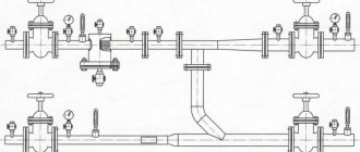
The first option will not be considered, because it has already been described. As for the second case, we need to take the photo below as a basis for analysis.
Piping diagram for a solid fuel boiler with a three-way valve
The diagram shows a double circuit: one large one passes through the radiators, the second is a short one through the bypass (this is a vertical red line, the beginning of which is at the top to the radiators, the end rests at the bottom of the valve). Until the boiler warms up, the coolant moves along a short circuit. The temperature has risen to the required level, the valve closes the bypass and opens the return (lower blue line).
And the third position, which is based on the distribution of coolant among consumers, in them the required temperature is not always the same. For example, an indirect heating boiler requires water at a higher temperature, for radiators at a lower temperature, and for heated floors even less.
Attention! In such a scheme, there is no need to install control shut-off valves in front of the boiler.
The wiring diagram for installing a three-way valve should be approximately as shown in the photo below.
Coolant distribution among consumers
Features of thermostatic three-way mixing valves
The service life of such products varies from 3 to 5 years and is determined by the valve model and its quality characteristics. Let's look at the main differences between different models:
- dimensions;
- threaded connection option;
- purpose (for heating communications or hot water supply).
Let's consider the characteristics of an average model of a three-way valve:
- as a rule, such devices are made of non-ferrous metals (brass, bronze);
- in order to enhance the anti-corrosion protection of three-way mixing devices, their body is coated with a protective layer of nickel or chromium;
- the maximum operating pressure in the communication on which the valve is installed should not exceed 10 atmospheres or 1 MPa;
- Installation of such products is allowed in communications with a certain temperature of the working environment. The temperature indicator should not exceed a certain mark, namely +95 °C. However, in some cases, it is allowed to install three-way valves in communications whose temperature reaches 110 °C (for example, solar panels);
- manual control of such devices allows you to regulate the temperature of the coolant in the range from 20 to 60 °C;
- threaded connections of such mixing valves can have the following geometric parameters: Rp3/4; G3/4; G1; G1 ½ (parameters are indicated in inches);
- The throughput rate of such products varies from 1.6 to 2.5 m³/h.
Design elements of a three-way mixing valve
Three-way valves for heating with a fixed coolant temperature
This is the so-called budget option. In terms of price, it is 30-35% cheaper than devices with drives. How is he different from everyone else? There are no rods, sensors, or thermal heads in its design. There is a so-called thermostatic element installed inside, which is set to a certain coolant temperature. For example, it can be either +45°C or +65°C. That is, the indicator can be anything depending on the requirements of the hot water consumer.
The element is selected at the factory and installed there, so it is necessary to indicate on the valve what the outlet temperature will be after it. For example, if you need a valve for a heated floor, then choose one with a temperature of +45°C. The positive side of these devices is their low cost. Negative – the inability to adjust the temperature of the water.
Attention! If a valve of this type is installed on the bypass of a solid fuel boiler, then it is necessary to study the passport of the generator itself before purchasing. The main indicator for the valve is the temperature of the water in the return circuit. It is for this reason that the device is selected.
Thermostatic model
Types of drives
During operation, the valve is regulated depending on temperature by means of an external drive. Today you can find several types of drives that are worth paying attention to:
- simple thermostatic;
- thermostatic head;
- electric drive;
- servo.
The valves differ in different types of control; the simplest design is a conventional thermostatic device
Thermostatic drive. This type of drive is simple. In this case, the rod is pressed by expanding the working medium. Expansion occurs due to an increase in the temperature of the water. As a rule, small valves are equipped with this type of actuator at the production stage. This drive is removable and can be mounted on other devices if desired.
Three-way mixing valve with thermal head. In addition to the conventional drive, which operates due to the thermal expansion of the working medium, the operation of the valve can be controlled using a special thermostatic head. Such a head includes an element capable of responding to changes in ambient temperature. Also, these products are equipped with special remote sensors, which allows you to regulate their operation, focusing on the temperature of the working environment. The remote sensor is placed inside the pipeline (for direct contact with the coolant) and is connected to the drive via a capillary tube.
Electric drive. The rod can also be adjusted by an electric drive, which is controlled by a special controller. The coolant temperature in this case is measured by electrical sensors that transmit the received data to the controller. This method of controlling a three-way valve is the most common today, and also the most accurate.
Valve with servo drive. A servo drive is a simplified version of the electrical valve control option. In this case, there is no controller, and the valve operation is adjusted after receiving temperature data of the coolant directly by the drive.
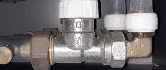
Rules for installing a three-way valve in a heating system
It is not difficult to install a three-way valve with or without a servo drive with your own hands. This is just a shut-off valve, but it should be noted that it can have different methods of fastening. There are usually two of them: threaded or flanged. In the first position, the thread can be internal or external. In any case, the connection to the pipes is made using sealing materials such as fum tape or tow. As for the flange connection, to ensure its tightness it is necessary to make a gasket from heat-resistant rubber or paranite.
Correct connection of the valve to the pipes
There are two nuances that relate to proper installation:
- The device is usually installed on the return circuit before the circulation pump, because the outlet pipe is always open.
- The valve must be installed in the pipeline system exactly in the arrow of the coolant movement. The latter is indicated on the device body.
Types of connection between valve and pipes
Prices for three-way valves
| Photo | Models | Characteristics | price, rub. |
| ESBE VRG131-25 | Connection diameter 25 mm Drive ARA661 with torque 6 Hm | 12500 | |
| ESBE VRG131-25 | |||
| ESBE VRG131-20 | Connection diameter 20 mm (threaded) Device without drive with thermal head Temperature range – 10÷110°С | 4500 | |
| ESBE VRG131-20 | |||
| Danfoss VF3-15 | Bore diameter 15 mm Temperature range 10÷130°С Flange connection Capacity 0.63 m³/h | 47000 | |
| Danfoss VF3-15 | |||
| Danfoss VRB3-32 | Bore diameter 32 mm Withstands pressure up to 16 atm. Maximum temperature +130°C Capacity 16 m³/h Material - bronze | 42000 | |
| Danfoss VRB3-32 | |||
| Navien | A universal device that is used in all types of heating boilers produced by the manufacturer. | 3000 | |
Danfoss VRB3-32
Prices for three-way valves for heating with a thermostat and actuator vary greatly. Basically, the whole point is in which heating systems they should be installed. This applies to the pressure inside the network and the temperature of the coolant. Of course, devices with a drive are more expensive.
The variety of three-way valves can sometimes make choosing them confusing. Not everyone can immediately determine which device needs to be purchased for a specific heating system. Therefore, contact us in the comments, and our specialists will answer all your questions.