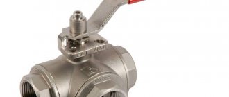
Modern heating consists not only of boiler equipment, pipe lines and batteries. It consists of elements that can be called by a general definition - shut-off and control valves. This is an integral part of the system. Each of them is important for changing the temperature regime of the coolant. A special role is played by a three-way valve for heating with a thermostat. The connection diagram can be made in different ways, but the principle of operation is the same: regulation or mixing of the coolant.
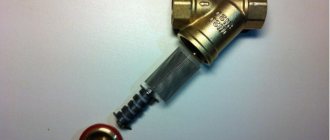
Three-way valve with thermostat
Why is it necessary to regulate heat flow in a heating system?
When drawing up a home heating project, it is necessary to perform a heat calculation, thanks to which the optimal equipment performance, mains power and thermal balance throughout the house are selected. During operation, the mode may change due to many reasons:
- change in outside temperature;
- solar Activity;
- gusts of wind;
- thermal radiation from household appliances.
As a result, the calculated temperature balance is disrupted. But you cannot remove or plug individual sections of heating batteries. To eliminate this situation, it is necessary to install additional elements with the help of which the temperature of the coolant is regulated.
The advantages of a three-way mixing valve include:
- simple installation;
- long service life;
- functional features;
- practicality;
- the ability to independently change the temperature of the liquid.
Among the negative aspects, it is necessary to highlight: high cost and inability to operate with contaminated flows
Usage and connection diagrams
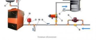
In order to prevent cold coolant from entering the jacket of a solid fuel boiler when it is heated, a connection diagram for a three-way valve with a primary circulation circuit is used:
Three way valve connection
A three-way valve cuts off cold water from the return pipeline so that condensation does not appear on the walls inside the solid fuel boiler chamber, which can significantly reduce the service life of the unit. The coolant moves in the primary circuit until it heats up to the temperature set on the valve thermoelement, in most cases this is 40-50? C. Once this temperature is reached, the thermostatic valve acts on the stem, gradually opening the flow of cold water from the heating system. To hydraulically adjust the entire system, a balancing valve is embedded in a small circuit. For normal operation of the boiler piping circuit, the circular pump must be installed after the three-way valve, and not in front of it; this is a very common mistake.
A continuation of this scheme could be the organization of a secondary circulation circuit, which involves its own pump and three-way valve for heating. The connection is made according to the following scheme:
Three way changeover valve
In the secondary circuit, hot water from the boiler is added to the heating system if there is a need for this, and the pump ensures circulation in this circuit. The three-way valve and pump are controlled by a controller, which receives information about the parameters of the coolant from sensors. The selection of water for an electric water heater is carried out between 2 circuits, where the coolant has the highest temperature; the connection of a three-way valve to the boiler in the primary circuit is done as shown in the previous diagram.
Most manufacturers of boiler room equipment install an additional circuit in their own heating units to equip DHW consumers. In order to maintain the parameters of hot water supplied to the house, equipment for switching the key pipe coil to the DHW circuit and back is installed from inside the boiler. The working principle and design of the three-way gas water heater valve involved in this process differs little from the products described above. There is a slight difference in the design, which is a straight manifold; a component moves from inside it, covering the side sections of the pipe. The rod rotates using a servo drive upon command from the built-in control unit of the boiler.
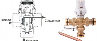
Another area of use is the control of floor heating; to do this, in most cases a three-way valve with a thermal head and a remote thermal converter is used. The general scheme looks like this:
Three-way mixing valve with thermal head
The circuit ensures that all living spaces are supplied with a coolant at the same temperature. A three-way valve is necessary to prevent overheating, since underfloor heating systems will not require the same hot water as that coming from the boiler room. The pump circulates in all circuits, and the valve mixes hot coolant into the supply manifold if necessary. Such a mixing unit is one of the simplified connection options; the diagram becomes difficult when temperature adjustment is required in all rooms separately.
Purpose of a three-way valve for heating with a thermostat: areas of application
A three-way valve with a thermal head is the main element of shut-off valves for the heating main. Based on its operating principle, it is designed to mix or separate coolant flows:
- separation fittings - used to distribute liquid simultaneously in several directions. The tap is included in the water intake systems of an individual home or industrial enterprise;
- mixing fittings are designed to mix liquids in order to organize effective thermoregulation. The faucet has 2 holes for incoming flows and 1 for outgoing flows.
The main purpose of the product is to ensure continuous circulation of liquid throughout the heating line to maintain the same comfortable temperature of the coolant and ensure uniform heating of the room.
It is recommended to install a three-way mixing valve when installing heated floors. With the help of a needle, the temperature regime is controlled; overheating of the coating is impossible.
The principle of operation of the mixer in the heating system
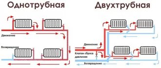
Connection diagrams for a three-way valve to a heating network
After all the analysis regarding the design of the valve and its operating principle, an understanding emerged of how it can be used in various heating systems. Most often it is used in three cases.
- In a heated floor system, the coolant temperature should be within +45°C. It is this mode that is supported by the device. This has already been discussed above, and it has been shown how it should work.
- To protect solid fuel boilers from the formation of condensation inside the firebox. This happens when relatively very cold return water enters the generator heat exchanger. This causes water droplets from condensed steam to form on the outer surfaces. This should not be allowed, because condensation shortens the life of the equipment.
- If there is a need to maintain different temperatures in different parts of the heating system.
The first option will not be considered, because it has already been described. As for the second case, we need to take the photo below as a basis for analysis.
Piping diagram for a solid fuel boiler with a three-way valve
The diagram shows a double circuit: one large one passes through the radiators, the second is a short one through the bypass (this is a vertical red line, the beginning of which is at the top to the radiators, the end rests at the bottom of the valve). Until the boiler warms up, the coolant moves along a short circuit. The temperature has risen to the required level, the valve closes the bypass and opens the return (lower blue line).
And the third position, which is based on the distribution of coolant among consumers, in them the required temperature is not always the same. For example, an indirect heating boiler requires water at a higher temperature, for radiators at a lower temperature, and for heated floors even less.
Attention! In such a scheme, there is no need to install control shut-off valves in front of the boiler.
The wiring diagram for installing a three-way valve should be approximately as shown in the photo below.
Coolant distribution among consumers
The design and principle of operation of a three-way valve in a heating system
Externally, the knot resembles a tee. It contains:
- 2 inlet pipe sections (pipe);
- 1 outlet pipe.
The operating principle of a three-way valve is to distribute, switch, and mix the coolant. With its help, you can regulate which of the two streams will go to the output, and in what proportion they will be mixed.
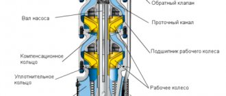
The crane structure consists of the following parts:
- brass (or stainless steel, or polymer) body;
- ball locking unit with through perforation on the walls;
- 2 Teflon rings (saddles) are used to secure the shutter; some models do not have them;
- butterfly handle;
- the spindle is necessary to connect the shut-off valve and the drive. It transmits torque to the bolt;
- sealing parts to ensure the tightness of the unit.
The shutter can be installed in the following modes:
- complete shutdown of the coolant supply;
- mixing liquid;
- division of the coolant flow between two outlets;
- redirection of flow.
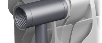
Sectional view of a three-way valve
Design and working principle of three-way valve
Very often the product looks like a simple tee made of brass or bronze, with an adjusting washer placed on top. Below it is a heat-sensitive component that presses on the operating rod extending from the housing. From the inside, a cone is attached to the rod, which fits tightly into the saddle. To understand how a three-way valve does not stop working, you need to learn its cross-sectional structure:
Three Way Thermostatic Mixing Valve
Water moves through the front and right sections of the pipe until its temperature rises or falls to a given value. The task and working principle of a three-way valve is to maintain the temperature of the coolant at the outlet within specified limits by mixing cold or hot water (depending on the circuit) from the left section of the pipe. When the parameters of the coolant go beyond the specified limits, the external drive presses on the rod. When it moves, the cone comes out of the seat and opens communication between all three channels. The process lasts until the front inlet section of the pipe is completely blocked, if the temperature parameters of the water do not stop changing.
Three way valve with thermal head
There is an internal valve mechanism of a different type; its design is similar to a ball valve. Such a three-way switching valve, instead of a seat with a cone, has a ball on the inside with a recess of a specialized shape. To redistribute the flow of heat carrier in such products, the drive must not press, but rotate the rod on which the ball is attached. Ball valves are not manufactured with high flow capacity and are mainly used in domestic heating systems. Another type of mechanism is that there is not a ball on the rod, but a section whose working part completely or partially closes one or two flows based on this.
Three way valve operation
Three-way valve for heating with thermostat: diagram and main functions
Despite the external similarity with a tee, the valve performs completely different functions. The unit, supplemented by a thermal head, is the main element of the shut-off valves.
Maintaining a comfortable temperature
To maintain a comfortable air temperature, you need to control the heating. This can be done in two ways. In any case, manipulations with coolant flows are necessary. Thermal mixing valves are recommended for installation in houses with heated floors
Qualitative change in the properties of radiators
To regulate the quality of the coolant, the heat generator must be switched to a lighter operating mode (cold flow is supplied to the batteries).
You should know this! In a private home, you can change the mode in the boiler equipment. In urban high-rise buildings, all that remains is to regulate the temperature in the radiator.
Using a mixer you can maintain a comfortable microclimate
Quantitative heat flow control
If it is impossible to change the temperature of the coolant in any way, you should regulate the amount of liquid using a three-way control valve. Fewer flows will pass through the pipeline, therefore, the air temperature in the room will decrease.
Such a device is a three-way valve with a thermostat. With its help, you can limit (increase) the amount of liquid that passes through the heating system. In other words, a smaller (larger) amount of coolant will pass through the batteries, and the temperature balance of the room will change accordingly.
You can install the regulator on the battery and the three-way unit separately, but to increase efficiency it is recommended to install a mixer with a thermostat.
Thread separation scheme
Varieties and purpose of each type
Three-way valves are mainly divided according to their operating principle. There are three positions here:
- mixing,
- dividing,
- switchable.
The designations on the body show what type of devices they belong to.
The former mix two coolant flows with different temperatures into one, while the latter, on the contrary, divide one flow into two. And still others simply switch the movement of water from one direction (circuit) to another. The first two varieties are similar in appearance to each other, so a diagram is applied to their body, which shows for what purpose the device should be used.
As for the third position, it is easy to distinguish it from the rest. It additionally has a block with the help of which switching occurs. A valve of this type is usually installed in a dual-circuit heating system when it is necessary to redirect the coolant flow from the heating system to the boiler and vice versa.
Switching type valve
Related article:
Thermostats with air temperature sensor. A separate material provides practical guidance on the selection and installation of thermostats.
Types of three-way valve actuators
| Actuator type | Operating principle | How it works |
| Saddle | Supplemented with a rod that makes translational movements up/down. | The saddle inside the assembly is covered by a cone attached to the end of the rod. |
| Rotary | Supplemented with a rotating ball (sector) | The wire rotates the rod element, causing the ball with the opening to open or block the movement of coolant between the nozzles. |
Rotary mixer
Conclusion
If we have a distribution valve and we are talking about protecting the boiler, then it is placed on the supply side. If we are talking about regulating the temperature in the circuits, then it is placed on the return line.
And vice versa, if the valve is a mixing valve, then it is installed on the return line for the safety of the boiler. If we are talking about adjusting the temperature in the circuit, then it is set to supply.
The valves always have arrows or letters that show the direction of flow. If you turn this valve upside down, the following may happen: first, your pump may not work, but you can find a middle position in any valve where the flow will still flow. But if the valve is a pressure valve, then this should not be done under any circumstances. The fact is that the coolant in this valve must get under the seat in order for it to lift it. Most valves have a spring-loaded valve, which is pressed against the seat by a spring; accordingly, if coolant enters from the other side, it will press on the valve and thus close it.
What happens the moment the valve closes? The flow stops, the pressure changes, and the valve, under the influence of the spring, tends to return back. As soon as it opened, the coolant flowed into the resulting gap and began to flow, and at that moment the valve closed. Then it opens again, because the pressure has changed again. This occurs with a frequency of 20-30 hertz, which sounds like a low-frequency growl. This should not be allowed under any circumstances, the valve should not growl, so install the valve as it should. It is necessary to do everything possible to ensure that the coolant moves either in letters or in arrows.
Types of three-way valve actuators
The unit is externally similar to a regular tee, with a valve installed on top. The operating principle is based on the rotary mode of the valve, which changes or shuts off two flows.
According to the type of control, the drive can be:
- manually adjustable;
- electrical;
- thermostatic.
The operating principle of each of them is different. Manual control is carried out using thumbwheels (rotary knobs). In order to change the temperature, you need to turn the tap to the desired position. The big disadvantage is the unevenness of the coolant and the heating system takes a long time to warm up. The operating principle does not allow you to constantly adjust the tap manually to achieve a comfortable temperature balance.
Three-way mixer with servo drive
Three way thermostatic valve
This product is equipped with a thermostat – gas or special liquid. The thermostat is located in a certain cavity inside the assembly. It responds to even the smallest fluctuations in the coolant.
As the temperature rises, the thermostat expands and sets in motion a piston system, which stops access to hot flows.
It is important! Before installing a unit with a thermostat, it is necessary to configure it extremely precisely: set the temperature limits, thanks to which the heating of the liquid in the heating system will be regulated.
The main advantage of the product is absolute autonomous operation.
Three way thermostatic valve
Motorized 3-way valve
This valve is equipped with servo drives and an electronic control unit, thanks to which the temperature regime of the coolant in the heating line is controlled and regulated. The main advantage of such control is maintaining the specified parameters in offline mode.
The principle of operation is as follows: the electronic unit measures the temperature of the coolant at the outlet, analyzes and gives a command to the drive through the controller, which, by changing its position, regulates the amount of cold and hot flow in the system.
Three-way thermostatic valve with electric drive
Diagram of a heated floor with a three-way valve
Once you have an understanding of what a three-way valve is and what its work is, you can consider various connection diagrams, depending on the purpose and role of the element in heating the house.
- Thermal mixing valve is installed in the following cases:
- To protect a solid fuel boiler from the effects of condensation and temperature shock after sudden power outages.
- The coolant in the underfloor heating circuits should warm up to no more than 45 °C, which is ensured by a mixing unit with a three-way valve.
- To maintain the required coolant temperature in different places of the system.
- To protect a solid fuel heating unit from the formation of condensation, it is impossible to allow cooled water from the radiator network to be supplied to the boiler tank during its heating.
To do this, use the following boiler connection diagram with a bypass and a three-way mixing valve:
The scheme works like this. Until the heat generator warms up, water circulates in a small circle through the bypass. When the coolant in the return heats up to 50-55 °C, the valve begins to open and mix in cold coolant from the system. When the heater reaches operating mode, the bypass is closed and the entire flow goes through the radiators.
In a heated floor system, this element performs the same functions. The circulation pump circulates the coolant through the heating circuits until it begins to cool. As soon as this happens, the sensor and thermal head will operate, after which the three-way valve will begin to add hot water coming from the boiler to the closed circuit.
How to correctly install a heated floor manifold, pump and valve with your own hands is shown in the diagram:
The next example of the use and connection of this important part is the connection between a solid fuel heat generator and a buffer tank, which is a heat accumulator.
To warm it up completely quickly enough, the temperature of the supplied coolant must be from 70 to 85 ° C, which is not at all necessary in a radiator heating system. A three-way valve installed behind the container along with a separate circulation pump helps to lower it.
Important. When installing the mixing valve, remember that the pump should be located on the side where the three-way valve is always open.
A complex heating system of a large cottage can have many consumers connected via a hydraulic valve and a distribution manifold.
Moreover, coolant with a different temperature must be supplied to each of the circuits. The highest is needed for an indirect heating boiler, so there are no control valves on the supply line to it. The remaining consumers need a colder coolant, and therefore they are connected through three-way valves.
- Depending on the direction of flow, the thermostatic valve is available in two models:
- T-shaped or symmetrical design. With this connection, hot and cold water enters through the side holes, and after mixing, the liquid flows out through the central passage.
- L-shaped or asymmetrical design. In this case, hot water comes from one side, and cold water from below. Subsequently, the mixed flow exits from the second side passage.
Wiring diagram for a three-way mixing valve.
A mixing valve equipped with a thermostat is installed if it is necessary to ensure a stable temperature of the coolant.
- Considering the mixing unit, we can distinguish the following components in it:
- Check Valve;
- temperature sensor;
- circulation pump;
- three-way mixing valve.
Diagram of a mixing unit for heated floors
The connection diagram includes a circulation pump mounted on the supply. Then a temperature sensor is installed, which is necessary to determine the degree of heating of the incoming water.
After this comes the thermostatic valve. A check valve with an outlet is mounted on the “return”, which is connected to a pipe with circulating cooled liquid directed to the mixing valve.
- With a similar connection diagram, the coolant moves along the following route:
- Pumping hot water using a circulation pump into the equipped heated floor system. The coolant temperature can reach 80°C.
- Mixing with cold water through a three-way valve. As a result, the desired temperature is achieved.
- Distribution of coolant through underfloor heating pipes.
- The return of the cooled water to the “return”, from where it is taken into the three-way valve for subsequent mixing with the hot liquid.
With such a connection, the temperature sensor regulates the degree of heating of the water entering the water circuit. There are other ways to control. The most ineffective is the manual method, when you need to change the flow by turning the handle.
There is a control option using a servo drive, commands to which are received from the controller in accordance with signals received from sensors.
Diagram of components based on three-way mixing and thermostatic valves for heated floors.
The thermostatic tap plays an important role when installing a water heated floor. By preventing the coolant entering the pipes from overheating, it saves fuel. In addition, safety is ensured during the operation of a rather complex heating system and the trouble-free service life is extended.
Installation diagram of a three-way separating valve
Provides quantitative control for the consumer - by changing the coolant flow. It is used if, according to the operating conditions of the heat source, it is permissible to bypass the coolant into the return pipeline and it is not allowed to stop circulation in the source circuit.
This scheme for installing a three-way valve has been widely used in water and air heating units connected from an autonomous boiler room. To link hydraulic circuits, the pressure loss at the balancing valve in the bypass line must be equal to the pressure loss at the consumer.
This installation diagram for a three-way valve is intended for connection to a pipeline with excess pressure. The coolant circulation in the consumer circuit is ensured due to the excess pressure created by the circulation pump in the heat source circuit.
Installation diagram of a three-way separating valve
Schemes for installing a three-way mixing valve for separation
Provides quantitative control at the consumer using a three-way mixing valve. It is used if, according to operating conditions, cessation of flow in the source circuit is not allowed, but the bypass of coolant from the supply pipeline to the return pipeline is acceptable.
Similar schemes for connecting three-way valves have become widespread in the piping of air heaters and air coolers, as well as in water heating units installed in autonomous boiler houses.
It is recommended to install a balancing valve with a hydraulic resistance equal to the consumer resistance on the mixing pipe of the three-way valve. Circulation through the consumer and bypass is carried out due to excess pressure in the source circuit.
With the correct selection of the valve and hydraulic coupling of the bypass with the consumer circuit, the flow through the heat source is constant, and in the consumer circuit it is variable.
Connection diagram of a three-way mixing valve for flow separation to a pressure manifold
Since the water flow moves in the opposite direction to the direction of flow in the mixing valve, some valves may increase noise and vibration, as well as reduce the permissible pressure drop across the valve.
Installation diagram of a three-way mixing valve for separation to a hydraulic arrow When connecting a unit with a three-way separation valve to a heat source directly or to a free-flow collector, it is necessary to install a circulation pump in the supply or return pipeline. The pump can be common to several circuits.
The connection diagram of a three-way valve dividing the flow with an additional bypass in the consumer circuit parallel to the mixing line is used provided that the temperature regime of the source exceeds the temperature regime of the consumer.
The peculiarity of this scheme is that the flow rates in the source and consumer circuits will be constant, and overheated coolant will not flow to the consumer. The consumer will be provided with quality regulation. For this circuit to work, it is necessary to install a pump in the consumer circuit and in the source circuit.
If gas is available, the most economical way to heat a private home is a double-circuit gas boiler.
Or, as an option, an electric boiler.
Types of thermostats for radiators
Related article:
A thermostat for a heating radiator will help maintain a comfortable microclimate in each room. This article describes the design options for these devices, methods of their installation, as well as several popular models of thermostats with prices and characteristics to make your choice easier.
Installation of thermostats is possible on battery passage plugs. With their help, the liquid supply to the product is partially or completely blocked. A faucet equipped with a thermostat works on the same principle. It is enough to set the parameters once, and the entire system will subsequently function in the specified mode. Electronic components have particular accuracy and functionality.
You should know this! The thermostat cannot change the original power data of the equipment. However, with its help you can create an optimal temperature balance and a comfortable indoor microclimate.
Thermostat installed on the radiator
Three Way Automatic Radiator Valve for Heating
In the process of designing a heating system, the required power of heating devices is calculated. This makes it possible to ensure good living conditions in the premises. However, there may be external factors, as a result of which the temperature conditions in the house may change. To maintain a given temperature in the room, it is necessary to change the temperature of the coolant in the heating circuit. A three-way valve for heating is intended for this purpose. Thanks to the use of a thermostat, temperature control becomes much more comfortable.
An additional purpose of such a valve is the distribution of the coolant along a wide variety of circuits. For example, water of one temperature must enter heating radiators, but in a “underfloor heating” system the temperature of the coolant must be different. The three-way valve does not serve to reduce the flow of the operating medium, but only mixes several flows into one, giving it the set temperature. Or it divides one stream into 2, going to different circuits.
The principle of operation of the thermostat
Classification according to the method of controlling the temperature of the flows
| Control type | Principle of operation | Advantages | Flaws |
| Mechanical | The basic operating principle of the thermostat is based on the physical properties of the temperature agent (gas or liquid) inside the head to expand under temperature influence. To work, just turn the knob with divisions and set it to the required temperature. | This is the simplest and most reliable device. It does not require external power to operate. | There may be an error, poor functionality |
| Electronic | Temperature control is fully automated. The data is displayed on the panel. The movement of the rod is controlled by a microprocessor. The device runs on batteries. | You can set your own comfortable temperature and set it to a time. | Large dimensions, it is necessary to monitor the battery charge and high cost |
Thermostat design
Installation method for temperature control in circuits
Now let's look at temperature control in the circuits. Here the picture is a little different; a certain manifold appears between the boiler and the mixing unit, because in this case the valve faces the side that can close towards the boiler. We must not allow this to happen, so here an intermediate section of the main line arises, which allows the boiler to operate regardless of whether the valve is closed or open. It also has its own pump.
Why do we have to place the valve this way? In order for the pump to operate at all times, the non-closing outlet or non-closing inlet must always be located on the pump side, directly or indirectly through the heating system or underfloor heating circuit. If we turn this three-way valve upside down, then the pump will simply have nowhere to take the coolant from. It will operate on a closed valve.
Advantages and disadvantages of three-way valves with thermostat and electric drive
It is recommended to install a three-way valve in houses with solid fuel boilers. This is due to condensate falling out at the beginning of the furnace. The valve cuts off cold flows. At the same time, the heated coolant is started along a short circuit.
An electric magnet or an electric motor can be used as a drive in such units. The advantages of fittings supplemented with an electric drive include precise regulation of the flow temperature. However, due to the fact that the fluid movement does not stop at any position of the rod, energy costs and coolant consumption increase.
Connection diagram for a three-way valve in a system with a solid fuel boiler
Diagram of operation of a valve with a seat mechanism:
With fifth wheel actuator
The cone (3) fixed to the rod (4) overlaps the seat (5).
Valves differing in their actuators can be of two types: separating and mixing.
The mixing valve (SV) has two inputs for one output. The main application is for heated floors. Different temperature streams arrive at the inputs, which, when mixed, equalize the temperature to the specified level.
A separating valve (VV) has the opposite situation: there are two outputs per inlet. The flow is divided by the valve into two different directions.
The differences are related to the number of balls: one in the SK, two in the RK. They are built into the outlet pipes. There are as many outputs as there are ball valves. The movement of water is indicated by arrows.
SCs are used more in heating lines. Separating – for DHW. One divided stream will have a constant thermal regime (the quality of the liquid is important here), in the second stream the regime can change (only the quantity is important).
Adjusting the rod allows you to achieve the required temperature in a constant circuit. A variable circuit can completely overlap.
How to choose the right three-way valve
Before choosing a three-way valve, it is important to familiarize yourself with the principle of its operation and decide on the type of product. In addition, you should pay attention to the manufacturer. There are many low-quality analogues from unknown manufacturers on the plumbing products market. Heating system repairs and consequences will be expensive. Therefore, in this case, savings are inappropriate.
Key points to pay attention to when purchasing:
- copper and brass fittings have a longer service life;
- A manually operated faucet is more reliable than an electronic one. However, its functionality is significantly lower;
- An electronic three-way valve with a drive is much more expensive and fails more often. The main advantage is a large set of functions.
Three-way valve made of copper with actuator
What is it and what is it for?
A three-way thermostatic valve is a mixer designed to change the temperature of the coolant in the heating system.
Purpose and scope of the device
Even if we take into account all the heat losses and arrange the heating circuit in full accordance with the thermal calculation data, it will not be possible to exclude a malfunction in the heat balance as a result of the influence of external factors (temperature changes, wind loads, etc.).
In order to respond to these processes in a timely manner, maintaining a comfortable temperature in the room for a long time, shut-off and control valves - three-way thermostatic valves - are installed in the main line.
They are used both in conventional radiator heating circuits and in underfloor heating systems, where they provide:
- Redirection (distribution) of coolant flows.
- Mixing coolant flows with different temperatures to obtain a given temperature level.
- Protection of the floor covering from overheating (in underfloor heating systems).
For the same purpose, three-way thermal valves are often used in hot water supply systems, where they perform the function of a familiar mixer.
Technical characteristics of three-way valves
The main technical characteristics of three-way thermomixing valves are:
- Throughput: consumption of cubic meters of water per hour at nominal temperatures (20°C) and pressure.
- Inner diameter of pipes.
The parameters of the throughput and internal sections of all 3 pipes of three-way valves are most often the same.
- Maximum operating pressure.
- Dynamic range of regulation (the ratio of the throughput of a thermal valve under conditions of a fully open shutter to the same indicator with a half-closed shutter).
On a note! The dynamic range of control of three-way thermostatic valves, such as 50:1 or 30:1, belongs to the class of average. The best control properties are shown by devices with a dynamic control range of 100:1.
Sizes and nominal operating pressure values of three-way thermostatic valves are regulated by GOST 28338-89 and 26349-84, respectively.
What materials are three-way thermal valves made of?
A variety of metals and alloys are used to produce three-way thermostatic valves. When it comes to industrial facilities, the following are most often used:
Cast iron. It has anti-corrosion properties and fairly high strength. However, if production and operation technologies are violated, cast iron products can be quite fragile.
Black carbon steel. The material is durable, cheap, but susceptible to corrosion. To smooth out the last drawback, three-way valves are nickel-plated and chrome-plated.
Stainless (alloy) steel. The parameters are higher due to the addition of an alloy of nickel and chromium. High strength, resistance to oxidation and corrosion provide products with a long service life. However, such thermal valves are significantly more expensive.
For heating systems of private houses, brass three-way valves are most often used. Their temperature regime is limited to 200 °C, but within the allowed temperature range, brass devices can work for quite a long time. No less popular are polymer products used in the corresponding heating or plumbing circuits.
More expensive are three-way valves made of bronze, which are not inferior to their brass counterparts in strength. Bronze products are usually installed in copper heating circuits.
Important! Sometimes on sale you can find shut-off valves made of silumin (a low-strength aluminum alloy with silicon). Outwardly, they are very similar to products made of stainless steel or brass, but at the same time they are several times cheaper and, unfortunately, last only as long as they are priced at.
The internal locking mechanism in household products may be made of ceramic (with the exception of three-way motorized thermal valves). Ceramic mechanisms are chemically inert and durable, but are extremely sensitive to the purity of the transported coolant. Its low quality is the reason for the rapid wear of ceramic elements.
Review of models and manufacturers of three-way valves
To make the right choice, you need to compare the parameters of different models, clarify information about the manufacturer and compare prices.
We offer a short overview of leading manufacturers.
Three-way valve with electric drive "Esbe"
Shut-off valves are distinguished by high quality, accuracy and affordable cost. In the manufacture of shut-off valves, a special brass alloy is used. Three-way valves are equipped with a servo drive.
We can highlight the VGR131 DN25 sample with an electric drive and this is an indicator of the highest quality of the manufacturer. Not all products are equipped with a servo or electric drive.
Three-way valve "Esbe"
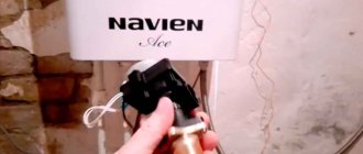
Three-way valves "Navien"
The manufacturer "Navien" is known in the production of boiler equipment. Three-way valves are manufactured to regulate the flow of solid fuel equipment. The production of three-way valves and boilers in one place is a significant plus. This guarantees the efficient operation of the entire heating system.
Three-way valve "Navien"
Danfoss three-way valves
A fairly popular German company produces three-way valves with electric drive, which are easy to operate, durable and reliable. The taps are quite compact. The most important thing is to choose the right model, then the result will be achieved.
In addition to the above advantages, we can note:
- accuracy of temperature control;
- sustainability;
- simple maintenance;
- the work is fully automated.
Danfoss three-way valve
Choosing a three-way valve: features of models from different companies
To select a suitable valve, it is necessary to compare all the characteristics of different models, namely the type of actuator, type of drive, presence and type of thermostat, as well as the manufacturer and price of a three-way heating valve. It is worth paying attention to models from leading manufacturers.
Esbe 3-way valves: installation instructions and features
Among the main advantages of Esbe models are simplicity and affordable cost.
Three-way valve for heating manufactured by Esbe
Helpful advice! If you need to adjust the tap, avoid simple models, the main disadvantage of which is the inability to stabilize the outlet temperature.
When installing the valve, a number of features should be taken into account:
- The mixing unit allows you to create an additional circuit in the system, connected to the distribution manifold at two points, which guarantees continuous circulation of water at the outlet.
- The inlet flow is provided in case of need for additional heat.
- A valve with a thermostat is connected to the mixing unit.
- To increase the flow rate of pumping equipment, which is often insufficient due to the narrowness of the valves converging at one point, it is necessary to create an additional line that reduces the power consumption of the pump. However, such measures are not relevant for all Esbee models.
- If there is a need for a second line, it is assumed that a balancing valve is installed or a pump is connected to this additional line, which leads to equalization of the temperatures of the inlet and outlet flows.
Esbe valve integrated into the heating system
Navien three-way valves: features and advantages
The Navien company specializes in the production of heating boilers. The three-way valves of this equipment are designed to change priorities between heating water for water supply and the heating system. These valves are worth purchasing if you have Navien equipment, because components and equipment from the same manufacturer are the key to long and efficient operation of the system.
Danfoss three-way valves: features and benefits
Danfoss valves are used in heating and water supply systems. Among the advantages of this type of equipment:
- stability and accuracy of adjustment;
- ideal compatibility with other Danfoss thermostatic elements;
- reliability and long service life without loss of performance characteristics;
- ease of installation, maintenance and operation;
- fully automatic operation;
- Possibility of installation on the pipeline in any position except with the valve down.
Danfoss three-way valve
By carefully studying the technical characteristics and tips for choosing a three-way valve for heating systems, you can select the appropriate device for a specific room and operating conditions.
Price overview
Before you go to a retail outlet to purchase a three-way tap, you need to clarify all the technical points regarding the mixer and heating line. In addition, you can use our advice and look at reviews of manufacturers.
We offer an overview of trusted manufacturers and the estimated cost of fittings:
- Swedish offers faucets from RUB 3,900;
- "Honeywell" offers convenient and simple three-way valves for heating with a thermostat at a price of 5,500 rubles;
- Valtec entered the market not so long ago, but the products have proven themselves only on the positive side. Cranes can be purchased at a price of 3,500 rubles;
- offers mixers at prices starting from 3,550 rubles;
- Heimer products can be called leaders in the budget line. They can be bought from 2,000 rubles.
Three-way valve "Heimer"
Prices for three-way valves
| Photo | Models | Characteristics | price, rub. |
| ESBE VRG131-25 | Connection diameter 25 mm Drive ARA661 with torque 6 Hm | 12500 | |
| ESBE VRG131-25 | |||
| ESBE VRG131-20 | Connection diameter 20 mm (threaded) Device without drive with thermal head Temperature range – 10÷110°С | 4500 | |
| ESBE VRG131-20 | |||
| Danfoss VF3-15 | Bore diameter 15 mm Temperature range 10÷130°С Flange connection Capacity 0.63 m³/h | 47000 | |
| Danfoss VF3-15 | |||
| Danfoss VRB3-32 | Bore diameter 32 mm Withstands pressure up to 16 atm. Maximum temperature +130°C Capacity 16 m³/h Material - bronze | 42000 | |
| Danfoss VRB3-32 | |||
| Navien | A universal device that is used in all types of heating boilers produced by the manufacturer. | 3000 | |
Danfoss VRB3-32
Prices for three-way valves for heating with a thermostat and actuator vary greatly. Basically, the whole point is in which heating systems they should be installed. This applies to the pressure inside the network and the temperature of the coolant. Of course, devices with a drive are more expensive.
The variety of three-way valves can sometimes make choosing them confusing. Not everyone can immediately determine which device needs to be purchased for a specific heating system. Therefore, contact us in the comments, and our specialists will answer all your questions.
The nuances of installing a three-way valve in a heating system
In order to correctly install a three-way mixer, it is important to know some of the nuances on which the uninterrupted and efficient operation of the heating system will depend.
Each product comes with instructions; strict adherence to them is necessary to avoid troubles:
- Follow the instructions on the body to set the valve to the correct position.
The symbols on the body mean:
- A – straight forward.
- B – perpendicular or bypass stroke.
- AB – input and output are combined.
Marking on the mixer body
- It is important to determine the crane model. This determines where the coolant will come from to the tap;
- In a symmetrical (T-shaped) scheme, the liquid enters the holes from the end and exits after mixing through the center;
- in an asymmetrical (L-shaped) scheme, the warm flow enters through the end hole, and the cooled flow enters from below. After mixing, the coolant exits through the second end hole.
It is important! The drive or thermostat should not be located at the bottom.
After this, it is necessary to prepare the heating system. First, turn off the water, then check for sediment in the line, which can damage the mixer. For installation, you need to choose a convenient place with open access.
Mixer installation features
Connection diagram for distribution and mixing valve
Types of valves
According to functionality, this fittings are divided into 2 types:
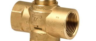
- Mixing valve. It has 2 inlet pipe sections and 1 outlet. Hot coolant from the boiler is supplied to one of the pipes, and the inlet of the second pipe section is combined with the “return”. Similarly, by mixing these two flows in the required proportions, the set temperature of the coolant is achieved at the outlet.
Working principle of three way mixing valve
- Dividing valve. It does the exact opposite job, zoning one flow into 2 circuits. Based on this, it only has 1 input, but 2 outputs. These taps are in demand in water heater piping systems. If you need to divide the flow of the coolant into 2 parts, then it is simply unrealistic to do without such fittings. Moreover, you can adjust the amount of liquid entering various circuits.
The design inside the two types of valves is noticeably different. A mixing-type valve has a rod with one closing element, which moves between 2 supply pipes. In the dividing valve, there are 2 similar elements on one rod. When one valve opens the first passage, the second valve automatically closes the second section of pipe.