Regardless of the type of communications, whether it is an autonomous or centralized system, it is important to correctly determine the physical parameters of individual elements of the service network in advance. Let's consider how you can independently calculate the diameter of the pipeline based on water flow or the required heat transfer of the coolant liquid. Let's get acquainted with the basic formulas without taking into account engineering subtleties that may be missed in the private sector.
Autonomous system of different pipes Source promtu.ru
Calculation methods
When developing projects for large-scale facilities, professionals use special engineering programs to draw up diagrams and drawings of future heating networks and hot/cold water supply. For simpler problems at the private sector level, solutions can be found using calculators that are published on the websites of manufacturers and sellers. The third option is to carry out calculations using ready-made formulas and tabular data, for example, about the speed of water in pipes.
You can do it even simpler - start from common solutions that have been tested at different sites, there is evidence of their effectiveness. However, the recommended schemes in individual construction do not always work properly. So, if you allow the diameter of the pipeline to be exceeded during selection, then the heating will have low heat transfer, and water will flow with low pressure. On the contrary, the use of narrowed channels increases pressure and the heating system will warm the house well. But at the same time, a large load is placed on the pipes and fittings, which shortens the service life of communications due to accelerated wear.
Using fittings to optimize the location of different channels Source kanaliza.ru
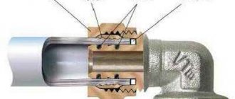
Finned tubes
Such products are manufactured using the helical rolling method. Ribs are applied to them, increasing the surface area that gives off heat. The use of such pipes makes it possible to reduce the weight of heat exchangers, because heat will also be given off by the finned pipe through which the liquid circulates.
Finned tube
Such a pipe, when compared with a regular smooth one, has a heat exchange area 2-3 times larger. The popularity of finned pipes is hampered by their high cost. Products are made of aluminum, brass and copper. Organizing a heating system using this type of pipeline requires significant financial costs, so we will not consider their calculation in this article.
If the system is not very branched and complex, the pipe diameter can be calculated independently. To do this, you need to have data on the heat losses of the room and the power of each radiator. Then, by looking at the table, you can determine the cross-section of the pipe corresponding to the supply of the required amount of heat. The calculation of complex multi-element circuits is best left to professionals. As a last resort, calculate it yourself, but try to at least get advice.
What to consider when calculating water supply
Engineering programs and calculators already contain all the necessary data that must be used to obtain the desired results. Therefore, let us consider in more detail the third method of calculations using ready-made formulas. Thus, the diameter of the pipe is calculated taking into account the throughput of the pipeline and the speed of fluid flow in the pipe:
Here the symbols mean:
- d – the desired cross-sectional size of the channel relative to the internal walls;
- q – flow rate of transported liquid in liters or kg per second or per hour;
- v – flow velocity in m/s;
- π is a constant value (the ratio of the circumference to the diameter).
To determine water flow or pipeline capacity, the following formula is used: q = 5 × q(0) × k .
Here, q(0) means a normative value that can be found in the current SNiP. For example, for a bathroom it is 0.25, for a faucet in the kitchen - 0.12, and for a flush cistern on a toilet, 0.1 units are enough. Coefficient k is needed when several consumption points are connected to the main line under study.
Multichannel network for servicing various points of consumption Source planlook.ru
It can be defined as follows: k = N × P. Here:
- f – volume of water consumed;
- N – number of liquid consumption points;
- P – the probability value of the simultaneous operation of several plumbing fixtures.
In turn, to determine the probability there is a formula: P = qhrμ × u/(q(0) × 3600 × N) . Without going into details, the product qhrμ is the maximum water consumption per hour. This indicator is normative, information is available in SNiP. As an example: The volume of cold water consumption should be within 5.6 liters, and the total with hot water should be about 15.6 l/s. By u in the formula we mean the number of people who constantly use the water supply.
An example of the location of water consumption points in a house for a small family Source jaxtr.com
Pipe patency
According to sanitary standards, which are taken into account by organizations when drawing up receipts without meters, there is about 360 liters of water per person per day. However, the flow rate, depending on the installed channels with a round cross-section, may differ from the standard. The actual result is influenced by several factors, among which the following are considered basic:
- Line length. Throughout the entire path, the moving liquid is subject to resistance from the inner walls of the pipe. Otherwise, this phenomenon is called pressure loss. That is, as you move, the speed of water in the pipeline decreases. As a result, the greater the difference between the pressure at the beginning and the end of a particular straight section, the more time will pass before a new portion of liquid enters the water supply. This is especially noticeable in old systems, where rust and growths gradually appear on the inside of the metal surface.
An example of different straight segments in the system Source septik-centr76.ru
- Diameter. The moment of resistance also matters here. On the one hand, in pipes with a small cross-section, the braking effect turns out to be a small surface area. On the other hand, the indicators are higher than in wider channels due to the proportionally different volume of transported liquid. That is, in the second case, with similar consumption, a person will receive the required displacement faster than through a thin pipeline.
- Compound. The modern market is represented by products for communication systems for water transportation, which are made of various materials. Thus, polypropylene walls have a noticeably less effect on reducing the flow rate than steel ones.
- Durability. There is a significant difference in the duration of maintaining the initially specified operating conditions. Corrosion and growths may appear on rough metal, which helps to reduce the cross-section of the line. That is, the initial calculations of the pipe diameter based on flow rate will ultimately turn out to be unfair. There are no such phenomena on smooth polymer walls. Their service life can exceed older analogues by up to 200 times.
Example of a clogged metal pipe Source ytimg.com
- Nodal connections. Any areas with fittings, regardless of installation method, rotations and separations provide additional resistance.
The summary tables indicate the throughput of water supply channels depending on the cross-section of the pipe (DN - nominal or nominal diameter) and the speed of fluid movement in the pipeline under one or another pressure.
| Pressure | Throughput or water flow (kg/h) at flow speed below 0.15 m/s | |||
| Pa/m | Mbar/m | 15 mm | 20 mm | 25 mm |
| 90 | 0,9 | 173 | 403 | 745 |
| 92,5 | 0,925 | 176 | 407 | 756 |
| 95 | 0,95 | 176 | 414 | 767 |
| 97,5 | 0,975 | 180 | 421 | 778 |
| 100 | 1 | 184 | 425 | 788 |
| 120 | 1,2 | 202 | 511 | 943 |
| 140 | 1,4 | 220 | 511 | 943 |
| 160 | 1,6 | 234 | 547 | 1015 |
| 180 | 1,8 | 252 | 583 | 1080 |
| 200 | 2 | 266 | 619 | 1151 |
| 220 | 2,2 | 281 | 652 | 1202 |
| 240 | 2,4 | 288 | 660 | 1256 |
| 260 | 2,6 | 306 | 713 | 1310 |
| 280 | 2,8 | 317 | 742 | 1364 |
| 300 | 3 | 331 | 767 | 1415 |
See also: Catalog of companies that specialize in engineering systems (heating, water supply, sewerage and others) and related work
| Pressure | Throughput or water flow (kg/h) at a flow speed within 0.15 m/s | |||||
| Pa/m | Mbar/m | 32 mm | 40 mm | 50 mm | 65 mm | 80 mm |
| 90 | 0,9 | 1627 | 2488 | 4716 | 9612 | 14940 |
| 92,5 | 0,925 | 1652 | 2524 | 4788 | 9756 | 15156 |
| 95 | 0,95 | 1678 | 2560 | 4860 | 9900 | 15372 |
| 97,5 | 0,975 | 1699 | 2596 | 4932 | 10044 | 15552 |
| 100 | 1 | 1724 | 2632 | 5004 | 10152 | 15768 |
| 120 | 1,2 | 1897 | 2898 | 5508 | 11196 | 17352 |
| 140 | 1,4 | 2059 | 3143 | 5976 | 12132 | 18792 |
| 160 | 1,6 | 2210 | 3373 | 6408 | 12996 | 20160 |
| 180 | 1,8 | 2354 | 3589 | 6804 | 13824 | 21420 |
| 200 | 2 | 2486 | 3780 | 7200 | 14580 | 22644 |
| 220 | 2,2 | 2617 | 3996 | 7560 | 15336 | 23760 |
| 240 | 2,4 | 2740 | 4176 | 7920 | 16056 | 24876 |
| 260 | 2,6 | 2855 | 4356 | 8244 | 16740 | 25920 |
| 280 | 2,8 | 2970 | 4356 | 8566 | 17338 | 26928 |
| 300 | 3 | 3076 | 4680 | 8992 | 18000 | 27900 |
| Pressure | Throughput or water flow (kg/h) at flow speeds above 0.3 m/s | |
| Pa/m | Mbar/m | 100 mm |
| 90 | 0,9 | 30240 |
| 92,5 | 0,925 | 30672 |
| 95 | 0,95 | 31104 |
| 97,5 | 0,975 | 31500 |
| 100 | 1 | 31932 |
| 120 | 1,2 | 35100 |
| 140 | 1,4 | 38160 |
| 160 | 1,6 | 40680 |
| 180 | 1,8 | 43200 |
| 200 | 2 | 45720 |
| 220 | 2,2 | 47880 |
| 240 | 2,4 | 50400 |
| 260 | 2,6 | 52200 |
| 280 | 2,8 | 54360 |
| 300 | 3 | |
The flow rate in channels with a circular cross-section depends, among other things, on the nature of the transported liquid. For example, for a viscous gravity medium, 0.1-0.5 m/s is considered optimal, and for a more liquid medium, 0.5-1 m/s. Indicators increase if devices for forced transportation are used. Thus, under discharge conditions, the speed can reach 0.8-2 m/s, and during suction - 1.5-3 m/s.
Relationship between characteristics
Of all the listed factors, pressure is the fundamental point: the lower it is, the larger the diameter of the pipes for water supply in a private house should be.
If this condition is not provided for, in the presence of an open water supply circuit, noise is possible that occurs with high pressure and small diameter pipes.
You should not greatly underestimate the pressure, since water will flow out of the tap in a weak stream, which is inconvenient to use.
An example of performing independent calculations
Let's look at how to calculate the diameter of a pipe for a cottage inhabited by 4 people. The list of consumption points includes a bathtub, shower stall and toilet; the kitchen has a washing machine and dishwashing equipment. Since there are several users and the fact that different equipment is operating simultaneously, we first need to determine the probability. Based on the available data, this would result in P = 5.6 × 4/(0.25 × 3600 × 6) = 0.00415 .
The water consumption in each room will be as follows:
- bathroom – q = 5 × 0.25 × 0.00415 = 0.00519 l/s;
- kitchen – q = 5 × 0.12 × 0.00415 = 0.00249 l/s;
- toilet – q = 5 × 0.1 × 0.00415 = 0.00208 l/s.
The next step is to determine the required pipeline diameter.
You can check the pipe cross-section with a regular ruler Source kipmu.ru
The flow rate in the pipe can be accurately calculated with parallel calculation of losses, coefficient of hydraulic friction and other required values. It is easier, despite the errors, to take information from ready-made tables. After all, there are no blanks on the construction market that differ from standardized sections.
If we take pressure water supply and the movement of liquid at a speed of 3 m/s as a guide, then according to calculations we will get the following options for optimal pipe diameters.
Bathroom - approximately 45 mm:
Kitchen - approximately 33 mm:
Toilet – approximately 30 mm:
Calculation of pipe diameter based on water flow
Determining the correct water flow
To determine the diameter of the pipe based on the flow rate of the passing liquid, you will need the values of the true water consumption, taking into account all plumbing fixtures: bathtub, kitchen faucet, washing machine, toilet. Each individual section of the water pipeline is calculated using the formula:
qc = 5× q0 × α, l/s
where qc is the value of water consumed by each device;
q0 is a standardized value, which is determined according to SNiP. We take for a bath - 0.25, for a kitchen faucet 0.12, for a toilet -0.1;
a is a coefficient that takes into account the possibility of simultaneous operation of plumbing fixtures in the room. Depends on the probability value and the number of consumers.
a = f (N × P)
In sections of the main line where water flows for the kitchen and bath, for the toilet and bath, etc. are combined, a probability value is added to the formula. That is, the possibility of simultaneous operation of a kitchen faucet, bathroom faucet, toilet and other appliances.
The probability is determined by the formula:
Р = qhr µ × u/q0 × 3600 × N,
where N is the number of water consumers (appliances);
qhr µ is the maximum hourly water flow that can be accepted according to SNiP. For cold water we select qhr µ =5.6 l/s, total flow rate 15.6 l/s;
u – number of people using plumbing fixtures.
Example of calculating water consumption:
The two-story house has 1 bathroom, 1 kitchen with installed washing machine and dishwasher, shower, 1 toilet. A family of 5 lives in the house. Calculation algorithm:
- We calculate the probability P = 5.6 × 5/0.25 × 3600 × 6 = 0.00518.
- Then the water consumption for the bathroom will be qc = 5 × 0.25 × 0.00518 = 0.006475 l/s.
- For the kitchen qc = 5 × 0.12 × 0.00518 = 0.0031 l/s.
- For a toilet, qc = 5 × 0.1 × 0.00518 = 0.00259 l/s.
Calculate the pipe diameter
There is a direct relationship between the diameter and the volume of flowing liquid, which is expressed by the formula:
Q = (πd²/4)•w
where Q is water flow, m3/s;
d – pipeline diameter, m;
w – flow velocity, m/s.
By transforming the formula, you can select the value of the pipeline diameter, which will correspond to the consumed volume of water:
Yulia Petrichenko, expert
d = √(4Q/πw), m
The water flow rate can be taken from Table 2. There is a more complex method for calculating the flow rate - taking into account losses and the coefficient of hydraulic friction.
This is a rather voluminous calculation, but in the end it allows you to get an accurate value, unlike the tabular method. Table 2. Liquid flow rate in the pipeline depending on its characteristics
| Pumped medium | Optimal speed in the pipeline, m/s | |
| LIQUIDS | Gravity movement: | |
| Viscous liquids | 0,1-0,5 | |
| Low viscosity liquids | 0,5-1 | |
| Pumpable: | ||
| Suction line | 0,8-2 | |
| Discharge pipeline | 1,5-3 | |
| GASES | Natural craving | 2-4 |
| Low pressure (fans) | 4-15 | |
| High pressure (compressor) | 15-25 | |
| COUPLES | Overheated | 30-50 |
| Saturated vapor at pressure | ||
| More than 105 Pa | 15-25 | |
| (1-0.5)*105 Pa | 20-40 | |
| (0.5-0.2)*105 Pa | 40-60 | |
| (0.2-0.05)*105 Pa | 60-75 | |
Example: Let's calculate the diameter of the pipe for the bathroom, kitchen and toilet based on the obtained water consumption values. We select from Table 2 the value of the water flow speed in the pressure water supply pipe – 3 m/s.
Then the diameter of the pipeline is determined:
for the bathroom d = √(4*0.006475/3.14*3)=0.052 m
for toilet d = √(4*0.00259/3.14*3)=0.033 m
for the kitchen d = √(4*0.0031/3.14*3)=0.036 m
Heating system
Here the main task that needs to be solved with the help of a coolant liquid is to provide the heating devices with the required amount of heat. Before calculating the diameter of the pipe, you will need to determine the heat loss of the house and select radiators with optimal power. You will also need data on the length of the pipeline and the design of the working system (method of water circulation, with one or two channels).
Two-pipe autonomous heating scheme Source kupisantehniky.ru
To calculate the diameter of heating pipes, you can use the following formula:
Here:
- d – the required value of the internal diameter;
- Q – load on a specific section of the system relative to the required amount of supplied heat;
- Δt° – difference between supply and return temperatures;
- V – coolant flow rate in the serviced area.
In autonomous heating systems, liquid can move at a speed of 0.2 to 1.5 m/s. In this case, the optimal values in practice are 0.3-0.7 m/s. At lower speeds, the likelihood of airing the system increases; at higher speeds, the system operates noisier.
Below is a table with the optimal values of hot water speed in polypropylene pipes depending on the amount of heat up to 20 kW (in kW) and the outer diameter of the channel (in mm). This takes into account the 80/60 operating mode and a temperature difference of 20 degrees Celsius.
| Warm | 20 | 25 | 23 | 40 | 50 | 63 | 75 |
| 3 | 0,2 | 0,1 | 0 | ||||
| 4 | 0,3 | 0,2 | 0,1 | 0 | |||
| 5 | 0,4 | 0,2 | 0,1 | 0 | |||
| 6 | 0,4 | 0,3 | 0,2 | 0,1 | 0 | ||
| 7 | 0,5 | 0,3 | 0,2 | 0,1 | 0 | ||
| 8 | 0,6 | 0,4 | 0,2 | 0,1 | 0 | ||
| 9 | 0,7 | 0,4 | 0,3 | 0,2 | 0,1 | 0 | |
| 10 | 0,7 | 0,5 | 0,3 | 0,2 | 0,1 | ||
| 11 | 0,8 | 0,5 | 0,3 | 0,2 | 0,1 | ||
| 12 | 0,9 | 0,6 | 0,3 | 0,2 | 0,1 | ||
| 13 | 1 | 0,6 | 0,4 | 0,2 | 0,1 | ||
| 14 | 1 | 0,7 | 0,4 | 0,3 | 0,2 | 0,1 | |
| 15 | 1,1 | 0,7 | 0,4 | 0,3 | 0,2 | 0,1 | |
| 16 | 1,2 | 0,8 | 0,5 | 0,3 | 0,2 | 0,1 | |
| 17 | 1,2 | 0,8 | 0,5 | 0,3 | 0,2 | 0,1 | |
| 18 | 1,3 | 0,8 | 0,5 | 0,3 | 0,2 | 0,1 | |
| 19 | 1,4 | 0,9 | 0,5 | 0,3 | 0,2 | 0,1 | |
| 20 | 1,5 | 0,9 | 0,6 | 0,4 | 0,2 | 0,1 | |
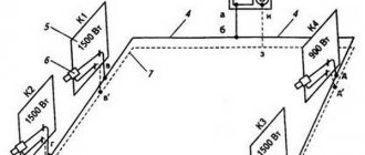
The task
The flow rate in the section of the intra-quarter domestic sewage system is Q=3 l/s. Select a reinforced concrete pipe.
Calculation of a sewer pipe (network section) consists of assigning a diameter and selecting a slope , see the calculation diagram below:
Design diagram of the sewer network section
In accordance with SP32.13330, the minimum possible diameter of the intra-block sewer system is 150 mm. This refers to the internal diameter .
Briefly about the main thing
The diameter of the pipeline determines the rate of supply of contents over the reporting period of time and the service life of communications.
You can calculate the optimal cross-section size for a particular section of the system using special engineering programs, calculators on the Internet, or using several formulas yourself.
When calculating the diameter of channels for water supply, the flow speed, pressure, required water consumption for servicing plumbing equipment and people living in the house, watering the garden or flower garden are taken into account.
When determining the diameter of the pipes for assembling the heating system, it is necessary to find out the load or the amount of heat needed to compensate for heat loss, the temperature difference between the supply and return, and the speed of movement of the coolant.
Determining the optimal cross-section of water supply systems
A professional calculation of the pipe diameter is made taking into account water consumption, the number of turns and joints, and the length of the water pipeline. For intra-apartment wiring, special calculation formulas are rarely used, but the internal cross-sectional dimensions are chosen:
- for risers – 20-25 mm;
- for supply to water points - 10-15 mm.
For complex wiring schemes, with a large number of joints, turns, a significant length of the system, or a decrease in pressure compared to the standard value, pipes with an increased cross-sectional size are used.