In the article we will consider systems with forced circulation. In them, the movement of the coolant is ensured by a constantly running circulation pump. When choosing the diameter of heating pipes, it is assumed that their main task is to ensure the delivery of the required amount of heat to heating devices - radiators or registers. For the calculation you will need the following data:
- General heat loss of a house or apartment.
- The power of heating devices (radiators) in each room.
- Pipeline length.
- Method of wiring the system (one-pipe, two-pipe, with forced or natural circulation).
That is, before you start calculating the diameters of the pipes, you first calculate the total heat loss, determine the power of the boiler and calculate the power of the radiators for each room. You will also need to decide on the wiring method. Using these data, you draw up a diagram and then just start calculating.
To determine the diameter of the heating pipes, you will need a diagram with the thermal load values assigned to each element.
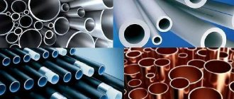
What else do you need to pay attention to? The fact is that the outer diameter of polypropylene and copper pipes is marked, and the inner diameter is calculated (subtract the wall thickness). For steel and metal-plastic ones, the internal size is indicated when marking. So don't forget this little thing.
How to choose the diameter of a heating pipe
It will not be possible to calculate exactly what cross-section of pipes you need. You will have to choose from several options. And all because the same effect can be achieved in different ways.
Let me explain. It is important for us to deliver the right amount of heat to the radiators and at the same time achieve uniform heating of the radiators. In systems with forced circulation, we do this using pipes, coolant and a pump. In principle, all we need is to “drive” a certain amount of coolant over a certain period of time. There are two options: install pipes of a smaller diameter and supply coolant at a higher speed, or make a system of a larger cross-section, but with less traffic. Usually the first option is chosen. And that's why:
- the cost of products with a smaller diameter is lower;
- they are easier to work with;
- when laid open, they do not attract so much attention, and when laid in the floor or walls, smaller grooves are required;
- with a small diameter, there is less coolant in the system, which reduces its inertia and leads to fuel savings.
Calculation of the diameter of copper heating pipes depending on the power of the radiators
Since there is a certain set of diameters and a certain amount of heat that needs to be delivered through them, it is unreasonable to calculate the same thing every time. Therefore, special tables have been developed, according to which, depending on the required amount of heat, the speed of movement of the coolant and the temperature indicators of the system, the possible size is determined. That is, to determine the cross-section of pipes in the heating system, find the required table and select the appropriate cross-section from it.
The diameter of the heating pipes was calculated using the following formula (you can calculate it if you wish). Then the calculated values were recorded in a table.
Formula for calculating the diameter of a heating pipe
Where:
D - required pipeline diameter, mm ∆t° - temperature delta (difference between supply and return), °C Q - load on a given section of the system, kW - determined amount of heat required to heat the room V - coolant velocity, m/s - selected from a certain range.
In individual heating systems, the coolant movement speed can be from 0.2 m/s to 1.5 m/s. Based on operating experience, it is known that the optimal speed is in the range of 0.3 m/s - 0.7 m/s. If the coolant moves more slowly, air jams occur; if it moves faster, the noise level increases significantly. The optimal speed range is selected in the table. The tables are designed for different types of pipes: metal, polypropylene, metal-plastic, copper. The values are calculated for standard operating modes: high and medium temperatures. To make the selection process more clear, let’s look at specific examples.
Reinforced PPRC polypropylene pipes - overview and characteristics
Every modern room, regardless of its purpose, needs to be provided with water resources. The instrument for providing any building or premises has been and remains water supply. A water supply network is a network of various types of pipes through which water flows to the place of its use.
Advantages of using pprc pipe
This article will focus on pprc pipe, which is reinforced internally with reinforcement. So, pprc reinforced polypropylene pipes are pipe products made from Poly Propylene Random Copolymer. This material is a static random copolymer, which is produced by adding an ethylene molecule to a network of polypropylene molecules. This material belongs to the category of polyolefins, which are highly environmentally friendly.
Random copolymer pipe products, in addition to the long name, are distinguished by a fairly large number of positive characteristics.
- They have low thermal conductivity.
- They have a high coefficient of resistance to various chemicals.
- This type of product is not exposed to processes such as corrosion and rusting.
- Characterized by high sound insulation.
- During the operation of the pprc pipe, the formation of sedimentary materials, such as salt or lime, does not occur on the inner surface of the material.
- They have high impact strength.
- This type of material has high resistance to repeated bending, after which it retains the integrity of the skin and primary mechanical properties.
- When exposed to high temperatures, polypropylene products do not undergo deformation and remain in their original shape.
- As mentioned above, this type of pipe fittings is highly environmentally friendly. This is manifested in the fact that after the end of their service life and subsequent disposal, they do not emit toxic substances that can harm humans and nature as a whole.
- With proper installation and operation they have a long service life.
Reinforced PPRC polypropylene pipes: specifics of reinforcement
Reinforced pprc pipe products are pipes made from polypropylene water fittings, the design of which, in addition to the original material, includes a thin additional layer of aluminum or fiberglass. This type of pipe fittings can be used in cold or hot water supply systems, as well as for other pipe communications, the chemical composition of which will not harm polypropylene. This type of pipe materials can also be used in fire extinguishing systems. So, in more detail about the types of reinforcement of pprc pipe fittings and their features:
Reinforcement with a layer of aluminum foil. The metal layer can be located inside or outside the product. This treatment gives the pipe additional properties, which are manifested in increasing its strength and resistance to temperatures.
Reinforcement with glass fiber gives pipe materials strength and increases resistance to mechanical stress. This type of reinforcement eliminates the formation of delamination of the structure of the lining of the pipe product, which can occur in the case of aluminum reinforcement.
Reinforced PPRC polypropylene pipes: installation methods
Installation of pipe communications made of polypropylene is relatively easy compared to a similar process in the case of steel or copper pipes. To work with this type of material you will need specific tools. Firstly, this is a special welding machine for soldering pipe parts together. This device is a tool with holes for mounting materials. During the work, the necessary pieces of pipe are placed in these holes, and after heating, they are connected to each other using specialized fittings.
To cut pipe fittings into the necessary parts, special scissors and pipe cutters for polypropylene pipes are used. With the help of these tools, pipes are easily divided into the necessary pieces. The system easily attaches to almost any surface using any holders that are attached with screws or glue.
Thus, the article described all the main characteristics of pipes made of static random copolymer (pprc), as well as their advantages over metal ones. Their typological features and installation specifics were also characterized and shown.
Reinforced PPRC polypropylene pipes
Application of pprc pipe in various indoor pipe systems. The article describes the main characteristics of pipe communications in the installation of which pprc pipes were used.
Calculation for a two-pipe system
There is a two-story house with a two-pipe heating system, two wings on each floor. Polypropylene products will be used, operating mode 80/60 with a temperature delta of 20°C. The heat loss of the house is 38 kW of thermal energy. The first floor has 20 kW, the second 18 kW. The diagram is shown below.
Two-pipe heating scheme for a two-story house. Right wing (click to enlarge)
Two-pipe heating scheme for a two-story house. Left wing (click to enlarge)
On the right is a table from which we will determine the diameter. The pinkish area is the zone of optimal coolant movement speed.
Table for calculating the diameter of polypropylene heating pipes. Operating mode 80/60 with a temperature delta of 20°C (click to enlarge)
Let's start the calculation.
- We determine which pipe needs to be used in the area from the boiler to the first branch. The entire coolant passes through this section, therefore the entire heat volume of 38 kW passes through. In the table we find the corresponding line, follow it to the pink-tinted area and go up. We see that two diameters are suitable: 40 mm, 50 mm. For obvious reasons, we choose the smaller one - 40 mm.
- Let's look at the diagram again. Where the flow is divided, 20 kW goes to the 1st floor, 18 kW goes to the 2nd floor. In the table we find the corresponding lines and determine the cross-section of the pipes. It turns out that we are dividing both branches with a diameter of 32 mm.
- Each of the circuits is divided into two branches with equal load. On the first floor there is 10 kW each to the right and left (20 kW/2=10 kW), on the second floor 9 kW each (18 kW/2)=9 kW). Using the table, we find the corresponding values for these areas: 25 mm. This size is continued to be used until the heat load drops to 5 kW (as seen in the table). Next comes a section of 20 mm. On the first floor we go 20 mm after the second radiator (look at the load), on the second - after the third. At this point there is one amendment made by accumulated experience - it is better to switch to 20 mm at a load of 3 kW.
All. The diameters of polypropylene pipes for a two-pipe system are calculated. For the return, the cross-section is not calculated, and the wiring is made with the same pipes as the supply. We hope the methodology is clear. It will not be difficult to carry out a similar calculation if all the initial data is available. If you decide to use other pipes, you will need other tables calculated for the material you need. You can practice on this system, but for an average temperature mode of 75/60 and a delta of 15°C (the table is located below).
Table for calculating the diameter of polypropylene heating pipes. Operating mode 75/60 and delta 15 °C (click to enlarge)
Rules and useful installation tips
- The easiest structures to install are single-layer ones. To install them, first cut the product with a pipe cutter, grind the edges and connect the structure using fittings or glue.
- Multilayer ones are mounted in the same way, the only difference is that when working with them you cannot use cold welding, it will not ensure the connection of all layers. Typically, multilayer parts are connected by hot welding or using special fittings.
- Reinforced pipes require special preparation before installation. The thing is that aluminum foil is attached to the fiber with glue, which means there is a certain risk of peeling. To avoid this, before welding a product reinforced with aluminum foil, you need to sort of solder the ends - remove part of the foil from the edge, and then solder the fiber on both sides. Water will not penetrate through such protection, which means the pipeline will remain intact.
Determination of pipe diameter for a single-pipe system with forced circulation
The principle remains the same, the methodology changes. Let's use another table to determine the diameter of pipes with a different principle for entering data. In it, the optimal zone of coolant movement speeds is colored blue, the power values are not in the side column, but are entered in the field. That's why the process itself is a little different.
Table for calculating the diameter of heating pipes
Using this table, we calculate the internal diameter of the pipes for a simple one-pipe heating circuit for one floor and six radiators connected in series. Let's start the calculation:
- 15 kW is supplied to the system input from the boiler. We find values close to 15 kW in the optimal speed zone (blue). There are two of them: in a line measuring 25 mm and 20 mm. For obvious reasons, we choose 20 mm.
- On the first radiator, the thermal load is reduced to 12 kW. We find this value in the table. It turns out that it goes further from it of the same size - 20 mm.
- On the third radiator the load is already 10.5 kW. We determine the cross section - still the same 20 mm.
- Judging by the table, the fourth radiator is already 15 mm: 10.5 kW-2 kW = 8.5 kW.
- On the fifth there is another 15mm, and after that you can already put 12mm.
Scheme of a one-pipe system with six radiators
Please note again that the table above defines internal diameters. Using them you can then find the markings of pipes made of the desired material.
It seems that there should be no problems with how to calculate the diameter of the heating pipe. Everything is quite clear. But this is true for polypropylene and metal-plastic products - their thermal conductivity is low and losses through the walls are insignificant, therefore they are not taken into account when calculating. Another thing is metals - steel, stainless steel and aluminum. If the length of the pipeline is significant, then the losses through their surface will be significant.
Types of fittings used
The pipe line consists of linear elements and connecting elements - fittings, which are installed at connections, transitions from one diameter to another, corner turns and bends of the system.
List of polypropylene fittings used for installation of utilities:
- Connecting couplings. Used for joining two linear segments.
- Angular turns. The wiring at the entrance to an apartment or floor rarely retains its linear configuration. In practice, due to the limited dimensions of the premises, the network is turned by 45° or 90° with bent corner bends.
- Transitions from one size to another. The ends of the adapters are made with different internal diameters, allowing you to create a pipeline from polypropylene pipes with different cross sections.
- Tees and cruciform bends. When several pipes are simultaneously joined in one unit, it becomes necessary to install a connecting tee or cross.
- Contours. When installing a water supply or heating line, it is necessary to route the pipeline around protruding building structures. Contours are installed in breaks in the linear main.
Do-it-yourself stripping for polypropylene pipes without special tools To increase reliability and maximum pressure, polypropylene pipes have a reinforced layer. But it interferes with the formation of a high-quality welded joint. The solution is stripping for polypropylene...
The design of the heating system cannot be completed without the use of an American combination coupling. This threaded part consists of a metal base on one side and a plastic end for welding on the other side. The result is a dismountable connection, convenient for installation work.
Features of calculating the cross-section of metal pipes
For large heating systems with metal pipes, heat loss through the walls must be taken into account. The losses are not that great, but over a long distance they can lead to the fact that the temperature on the last radiators will be very low due to the wrong choice of diameter.
Let's calculate the losses for a 40 mm steel pipe with a wall thickness of 1.4 mm. Losses are calculated using the formula:
q = k*3.14*(tв-tп)
Where:
q is the heat loss per meter of pipe,
k is the linear heat transfer coefficient (for this pipe it is 0.272 W*m/s);
tw — water temperature in the pipe — 80°C;
tп — room air temperature — 22°С.
Substituting the values we get:
q = 0.272*3.15*(80-22)=49 W/s
It turns out that almost 50 W of heat is lost per meter. If the length is significant, this can become critical. It is clear that the larger the cross-section, the greater the losses will be. If you need to take these losses into account, then when calculating losses, add losses in the pipeline to reduce the thermal load on the radiator, and then, using the total value, find the required diameter.
Determining the diameter of heating system pipes is not an easy task
But for individual heating systems these values are usually not critical. Moreover, when calculating heat loss and equipment power, the calculated values are most often rounded upward. This gives a certain margin, which allows you not to make such complex calculations.
An important question: where to get tables? Almost all manufacturers' websites have such tables. You can read it directly from the site, or you can download it for yourself. But what to do if you still haven’t found the necessary tables for the calculation. You can use the diameter selection system described below, or you can do it differently.
Despite the fact that different values (internal or external) are indicated when marking different pipes, they can be equated with a certain error. Using the table below you can find the type and marking for a known internal diameter. You can immediately find a corresponding pipe size made of a different material. For example, you need to calculate the diameter of metal-plastic heating pipes. You did not find a table for MP. But there is one for polypropylene. Select sizes for PPR, and then use this table to find analogues in MP. Naturally, there will be an error, but for systems with forced circulation it is acceptable.
Correspondence table for different types of pipes (click to enlarge size)
Using this table, you can easily determine the internal diameters of the heating system pipes and their markings.
Pressure classification
Polypropylene pipes vary in resistance to the pressure of the medium flowing through it.
Classification of polypropylene pipes.
According to this parameter, there is the following classification of products:
- N10 or PN10. This type is suitable for creating heating systems or water heated floors, where the heating temperature of the liquid is not higher than +45°C and the load on the walls does not exceed 10 atm.
- N16 or PN16. The products are operated at a temperature of the passing medium of no more than +60°C and loads on the walls up to 16 atm. This type of pipe is rare due to low demand.
- N20 or PN20. The products can be operated at pressures up to 20 atm. and temperatures up to +80°C. Heating and plumbing systems are installed from them.
- N25 or PN25. This type can withstand wall loads of up to 25 atm. and temperatures up to +95°C. Increased strength characteristics are due to the presence of an additional foil layer. Products are used in systems in which the flowing liquid is characterized by high temperature and pressure.
Selection of pipe diameter for heating
This method is not based on calculations, but on a pattern that can be traced when analyzing a fairly large number of heating systems. This rule was developed by installers and is used by them on small systems for private houses and apartments.
The diameter of the pipes can be simply selected following a certain rule (click to enlarge size)
Most heating boilers have two sizes of supply and return pipes: ¾ and ½ inches. It is with this pipe that the pipe is routed until the first branch, and then at each branch the size is reduced by one step. In this way you can determine the diameter of the heating pipes in the apartment. Systems are usually small - from three to eight radiators in the system, maximum - two or three branches with one or two radiators on each. For such a system, the proposed method is an excellent choice. The situation is practically the same for small private houses. But if there are already two floors and a more extensive system, then you have to count and work with tables.
How not to make mistakes when choosing sizes
What do you need to know when going to a hardware store to buy goods? To begin with, the operating conditions. Will this involve installing a drinking water supply? Or are you planning heating or underfloor heating? Believe me, in all these cases the diameter and dimensions of fittings for polypropylene pipes in mm will be different. That is why components are purchased for a specific construction task. In addition to the main function, it is necessary to consider whether there is heating in the room where the installation will be carried out.
Practical recommendations
The wrong choice of product diameters is fraught with many troubles: leaks (due to hydrodynamic shocks or excess pressure in the line), increased consumption of electricity (fuel) due to low efficiency of the system, and a number of others. Therefore, you should not install it according to the principle “like a neighbor (godfather, brother-in-law).”
If the circuit consists of dissimilar pipes, then special calculations will have to be made for each section (line) of the route. Separately - for plastic, metal (steel, copper), apply different coefficients and so on.
Only a specialist can solve such a problem. In such situations, you should not do the calculations yourself, as the error can be quite significant. The services of a professional will cost much less than the subsequent alteration of communications, and even during the heating season.
All devices (expansion tank, battery, etc.) of the circuit are connected using pipes of the same cross-section.
To avoid the formation of air jams (in case of some errors in the calculations), so-called air vents should be installed on each line.
