Calculation of heating pipes and the system as a whole consists of determining the thermal power, selecting the diameters of all pipe elements (hydraulic calculation), determining the dimensions of heating devices (thermal calculation) and selecting equipment.
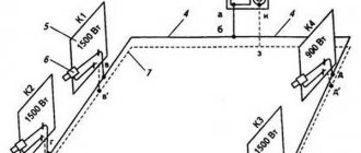
When designing a heating system, the first step is to draw up a diagram based on the house plan. The diagram shows:
- Location of boilers (or other heat generators).
- Circulation pumps.
- Places where heat pipes pass.
- Places for installing heating items.
Based on the diagram and calculating the thermal power of the system, you can calculate the diameter of the heating pipes in more detail.
What is needed for this
To calculate the diameter of the pipe, as a rule, the following factors are taken into account:
- Total heat loss of the home.
- What power do heating radiators have separately in each room.
- The total length of the circuit pipes.
- How is the system wired?
To be able to calculate the diameter of the pipes, it is necessary to determine in advance the total heat loss, the power of the boiler equipment and batteries for each room. It is also important which method will be chosen for pipe routing. Having all these parameters in hand, a future calculation scheme is drawn up.
It is also important to remember some of the specific markings of different pipes. Thus, on polypropylene pipes for heating a private house, the outer diameter is indicated (the same applies to copper products). To calculate the internal parameter, the wall thickness is subtracted from this indicator. Steel and metal-plastic pipes are marked by their internal cross-section.
Calculation by stages
Have you determined the initial data: drawn a diagram of the heating system, decided on the type, and timely calculated the amount of thermal power for all rooms? Then proceed further. Usually the calculation starts from the most remote room.
The volumetric flow rate of liquid is calculated using the formula:
G = 0.86*Q / 20 where: G – volumetric coolant flow rate, kg/h; Q – estimated amount of heat, W; 20 – temperature difference in supply and return. For calculations it is equal to 20 °C.
Using the above formula, the mass of the liquid is determined, but hot water is characterized at 80 °C by density p = 971.6 kg/m³. Therefore, the volume flow Vo is calculated by the formula:
Vo = G/r
If you know the volume and speed of movement, it is not difficult to calculate the cross-sectional area:
S = Vo / (3600 x Vt) where: S – cross-sectional area; Vo – flow rate (volume) of the coolant; Vt – selected fluid flow rate.
And at the end, the diameter is calculated:
D = square root of 4S/3.14.
Once you have calculated the diameter for the back room, calculating the size of the pipeline for the next room is not difficult. However, it is worth remembering that the total amount of heat for two rooms, etc. must be passed through this room. The calculation as a whole is not difficult, but for those who have not previously engaged in such calculations, it is quite cumbersome.
Therefore, in order to facilitate the process itself, there are tables that give the answer and solve the problem - how to determine the diameter of the heating pipe. From the tables it is clearly clear: the diameter of heating pipes with natural circulation needs to be large, since the flow speed is 0.3 m/s. It is worth choosing pipes according to the nearest larger diameter, taking into account the discrepancy in the logic of marking pipes made of different materials:
- Water and gas pipes made of steel - the internal diameter is specified.
- Electrically welded steel products - outer diameter.
- Polyethylene, metal-plastic, low-density polyethylene, polypropylene pipes for heating - outer diameter.
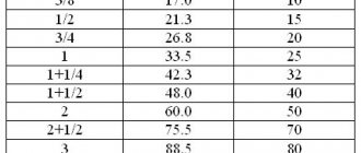
Diameters of copper and steel pipes for heating:
Pipe diameter table
Selecting the appropriate pipe diameter for heating
It is almost impossible to accurately calculate the pipeline cross-section. For these purposes, several methods are used, with approximately the same final result. As you know, the main task of the system is to deliver the required amount of heat to the batteries in order to achieve maximum uniform heating of the heating device.
In forced circuits, a pipeline, coolant and circulation pump are used for these purposes. Using this set of devices, it is necessary to supply the required portion of the coolant in a fixed time. There are two ways to achieve this task - using smaller diameter pipes in combination with a higher speed of water movement, or using a system with a larger cross-section in which the traffic intensity will be lower.
Reasons for the popularity of the first option:
- Lower price for thinner pipes.
- Great ease of installation.
- In open areas such systems are less noticeable. If they are placed on the floor or walls, smaller installation spaces are required.
- Narrow pipes contain less liquid. This leads to a decrease in system inertia and fuel savings.
Thanks to a set of standard diameters and a fixed amount of heat transported through them, there is no need to carry out the same type of calculations. For these purposes, special tables have been compiled: they allow, having on hand data on the required amount of heat, water supply speed and operating temperature of the heating circuit, to calculate the required dimensions. To determine what pipe diameters there are for heating, you need to find the necessary table.
To calculate the diameter of heating pipes, the following formula is used: D = √354x(0.86x Q/∆t)/V, where D is the desired pipeline diameter (mm), ∆t° is the temperature delta (the difference between supply and return), Q is load for a given section of the system, kW - a certain amount of heat required to heat the room, V - coolant velocity (m/s).
Autonomous systems usually have a coolant movement speed of 0.2 - 1.5 m/s. As practical experience shows, the most optimal speed in such cases is 0.3 m/s - 0.7 m/s. When this indicator decreases, there is a real threat of air jams; when it increases, the coolant begins to make a lot of noise when moving.
There are tables to select the optimal value. They contain data for pipes made of different materials - metal, polypropylene, metal-plastic, copper. When determining the diameter of heating pipes, as a rule, the emphasis was placed on standard operating conditions with high and medium temperatures. Some examples will help you understand the essence of the procedure.
general information
Basic moments
The absence of a circulation pump and generally moving elements and a closed circuit in which the amount of suspensions and mineral salts is finite makes the service life of this type of heating system very long. When using galvanized or polymer pipes and bimetallic radiators - at least half a century. Natural circulation of heating means a fairly small pressure drop. Pipes and heating devices inevitably provide a certain resistance to the movement of the coolant. That is why the recommended radius of the heating system we are interested in is estimated at approximately 30 meters. Of course, this does not mean that with a radius of 32 meters the water will freeze - the border is quite arbitrary. The inertia of the system will be quite large. Several hours may pass between lighting or starting the boiler and stabilizing the temperature in all heated rooms. The reasons are clear: the boiler has to warm up the heat exchanger, and only then the water will begin to circulate, and quite slowly. All horizontal sections of pipelines are made with a mandatory slope in the direction of water movement. It will ensure the free movement of cooling water by gravity with minimal resistance
What is equally important is that in this case all air pockets will be forced out to the top point of the heating system, where an expansion tank is mounted - sealed, with an air vent, or open.
All the air will collect at the top point.
Self-regulation
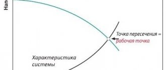
Heating a house with natural circulation is a self-regulating system. The colder the house, the faster the coolant circulates. How it works?
The fact is that the circulation pressure depends on:
Differences in height between the boiler and the lower heating device. The lower the boiler is relative to the lower radiator, the faster the water will flow into it by gravity. The principle of communicating vessels, remember? This parameter is stable and unchanged during operation of the heating system.
The diagram clearly demonstrates the principle of heating operation.
As the coolant temperature drops, its density increases, and it begins to quickly displace heated water from the lower part of the circuit.
Circulation speed
In addition to the pressure, the circulation rate of the coolant will be determined by a number of other factors.
- Diameter of distribution pipes. The smaller the internal cross-section of the pipe, the greater resistance it will provide to the movement of liquid in it. That is why, for distribution in the case of natural circulation, pipes with a deliberately oversized diameter are taken - DN32 - DN40.
- Pipe material. Steel (especially if damaged by corrosion and covered with deposits) has several times more resistance to flow than, for example, a polypropylene pipe with the same cross-section.
- Number and radius of turns. Therefore, if possible, it is better to make the main wiring as straight as possible.
- The presence, quantity and type of shut-off valves, various retaining washers and pipe diameter transitions.
Every valve, every bend causes a drop in pressure.
It is precisely because of the abundance of variables that an accurate calculation of a heating system with natural circulation is performed extremely rarely and gives very approximate results. In practice, it is enough to use the recommendations already given.
Calculation of two-pipe systems
We are talking about a two-story house with a two-pipe heating system, two wings on each floor. Polypropylene pipes are used to construct the system. Operating mode - 80/60, temperature delta - 20 degrees. The level of heat loss is 38 kW of thermal energy (first floor - 20 kW, second - 18 kW).
Calculation procedure:
- First you need to decide which pipe to decorate the area between the boiler and the first branch. The entire volume of coolant is transported here, transferring heat to 38 kW. The reference data indicates two suitable parameters - 40 and 50 mm. It is more profitable to stay at a smaller diameter of 40 mm.
- At the point of flow separation, 20 kW is sent to the first floor, and 18 kW to the second. According to the reference book, the section is determined. In this case, for each direction the optimal diameter is 32 mm.
- In turn, each circuit includes two lines with an equal load. On the first floor, 10 kW is distributed in both directions (20 kW/2 = 10 kW), on the second floor - 9 kW (18 kW/2) = 9 kW). A suitable value for these branches would be 25mm. It is more reasonable to use this parameter until the load is reduced to 5 kW. After this, they switch to a diameter of 20 mm. The first floor is translated by 20 mm immediately behind the second radiator. The second floor usually passes after the third device. As practice shows, this transition is best carried out at a load of 3 kW.
In this way, the diameter of polypropylene pipes for a two-pipe system is calculated. There is no point in determining the dimensions of the return pipe: they are taken the same as for the supply. This procedure is simple: the main thing is to have everyone’s initial data. If you plan to use a different type of pipe to organize the system, you need to use data for a specific material of manufacture. Calculating the diameter of heating pipes with natural circulation is somewhat different.
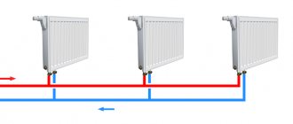
Methods for connecting a radiator to the main line
The heat transfer of radiators depends on the method of their connection to the main line.
There are three main types of connection:
- Diagonal;
- Lateral;
- Lower.
Let's look at the features of each of these methods in more detail.
Diagonal or cross connection
Diagonal, or cross, connection is the most effective. Maximum heating of the battery area is achieved, and there is practically no heat loss.
According to this scheme, the supply pipeline is connected to the upper radiator pipe, and the outlet pipe is connected to the lower pipe located on the opposite side of the device. For devices with a large number of sections, only the diagonal connection type is used.
Lateral or one-sided connection
Lateral, or one-sided, connection allows for uniform heating of all sections of the device.
For connection, the supply and discharge pipelines are connected on one side. Most often, this connection is used for heating installations with overhead wiring.
Heating heat transfer when radiators are connected sideways, with supply from top to bottom, is 97%. With the reverse movement of the coolant - from bottom to top - this figure is 78%
Bottom connection of radiator with pipeline
Bottom connection is not the most efficient heating scheme. However, it happens quite often, especially when the main pipeline is hidden under the floor.
The inlet and outlet pipes are connected to the lower pipes located on different sides of the radiator.
The heat transfer rate with bottom connection of radiators is 88%
Calculation of a single-pipe forced-type system
The principle applied is the same as in the previous case, but the algorithm of actions changes. For example, you can take the calculation of the internal diameter of a simple single-pipe heating system in a one-story house. The circuit has six radiators connected in series.
The procedure for calculating the diameter of the heating pipeline based on thermal power:
- The boiler transfers 15 kW of heat to the beginning of the system. According to the reference data, this section can be equipped with 25 mm and 20 mm pipes. As in the first example, it is better to choose 20 mm.
- Inside the first battery, the thermal load is reduced to 12 kW. This does not affect the cross-section of the outgoing pipe in any way: it remains the same value of 20 mm.
- The third radiator reduces the load to 10.5 kW. In this case, the cross-section remains the same - the same 20 mm.
- The transition to a smaller diameter of 15 mm occurs after the fourth battery, as the load is reduced to 8.5 kW.
- The coolant is transported to the fifth device through a 15 mm pipe, and after it there is a transition to 12 mm.
At first glance, it may seem that calculating pipe diameters for a heating system is easy and simple. Indeed, when polypropylene or metal-plastic products are used to organize the circuit, difficulties usually do not arise. This is explained by their low thermal conductivity and small heat leaks through the walls (they can be ignored). The situation is completely different with metal products. If the steel, copper or stainless steel pipeline is of considerable length, quite a lot of thermal energy will flow through its surface.
When you need to dot all the i’s
But a completely reasonable question arises. “How can you count something that is invisible and capable of disappearing instantly, literally out the window?” There is no need to despair of this struggle with the air; it turns out that there are quite clear mathematical calculations of the calories received for heating.
Moreover, all these calculations are hidden in official documents of state utility organizations. As usual in these institutions, there are several such documents, but the main one is the so-called “Rules for accounting of thermal energy and coolant”. It is he who will help solve the question - how to calculate Gcal for heating.
The actual problem can be solved quite simply and no calculations will be needed if you have a meter not just for water, but for hot water. The readings of such a meter are already “filled” with data on the heat received. When taking readings, you multiply it by the cost tariff and get the result.
Basic formula
The situation becomes more complicated if you do not have such a counter. Then you will have to be guided by the following formula:
- Q is the amount of thermal energy;
- V – volume of hot water consumption in cubic meters or tons;
- T1 - hot water temperature in degrees Celsius. More precisely, use temperature in the formula, but reduced to the corresponding pressure, the so-called “enthalgy”. But in the absence of a better, appropriate sensor, we simply use the temperature, which is close to enthalgy. Professional heat metering units are capable of calculating enthalgy. Often this temperature is not available for measurement, so they are guided by the constant “from the Housing Office”, which can be different, but is usually 60-65 degrees;
- T2 is the cold water temperature in degrees Celsius. This temperature is taken from the cold water pipe of the heating system. Consumers, as a rule, do not have access to this pipeline, so it is customary to take constant recommended values depending on the heating season. in season - 5 degrees; off-season – 15;
- The “1000” coefficient allows you to get rid of 10-digit numbers and get data in gigacalories (not just calories).
As follows from the formula, it is more convenient to use a closed heating system, into which the required volume of water is once poured and in the future there is no further supply. But in this case, you are prohibited from using hot water from the system.
The latest developments in the field of radiators, to some extent, may allow you to keep warm, but the desire to count everything will still not disappear.
The use of a closed system forces us to slightly improve the given formula, which already takes the form:
Q = ( (V1 * ( T1 – T ) ) – ( V2 * ( T2 – T ) ) ) / 1000
- V1 is the coolant flow rate in the supply pipeline, regardless of whether the coolant is water or steam;
- V2 - coolant flow in the return pipeline;
- T1 is the temperature of the coolant at the inlet, in the supply pipeline;
- T2 is the temperature of the coolant at the outlet, in the return pipeline;
- T - cold water temperature.
Thus, the formula consists of the difference of two factors - the first gives the value of the heat received in calories, the second - the value of the heat output.
Helpful advice! As you can see, there is not a lot of mathematics, but you still have to carry out calculations. Of course, you can immediately rush to your calculator on your mobile phone. But he advises you to create simple formulas in one of the most famous computer office programs - the so-called Microsoft Excel spreadsheet processor. included in the Microsoft Office package. In Excel, you can not only quickly calculate everything, but also “play” with the source data and simulate various situations. Moreover, Excel will help you build graphs of heat receipt and consumption, and this is an “unkillable” map for a future possible conversation with government agencies.
How to calculate metal pipes
Large heating systems equipped with metal pipes require taking into account heat loss through the walls. Although on average these figures are quite low, on very long branches the total value of lost energy is quite high. Often because of this, the last batteries in the heating circuit do not heat up well enough. There is only one reason - the diameter of the pipes was chosen incorrectly.
An example would be the determination of losses of a 40 mm steel pipe with a wall thickness of 1.4 mm. For the calculation, the formula is used q = kх3.14х(tв-tп), where q is the heat loss of a meter of pipe, k is the linear heat transfer coefficient (in this case it corresponds to 0.272 W*m/s), tв is the temperature of the water inside (+80 degrees), tп - air temperature in the room (+22 degrees).
To get the result, you need to substitute the required values into the formula:
q = 0.272x3.15x(80-22) = 49 W/s
The picture that emerges is that every meter of pipe loses heat in an amount of almost 50 W. On very long pipelines, the total losses can be simply catastrophic. In this case, the volume of leaks directly depends on the cross-section of the circuit. To take into account such losses, a similar indicator on the pipeline must be added to the indicator for reducing the thermal load on the battery. Determination of the optimal pipeline diameter is carried out taking into account the total value of leaks.
Typically, in autonomous heating systems, these indicators are not critical. In addition, during the procedure for determining heat loss and boiler power, the data obtained is usually rounded up. Thanks to this, a safety stock is created, freeing from complex calculations.
Formulas for calculations and reference data
Calculation of the heat load for heating involves determining heat losses (Tp) and boiler power (Mk). The latter is calculated by the formula:
- Mk – thermal performance of the heating system, kW;
- Тп – heat losses of the house;
- 1.2 – safety factor (20%).
A twenty percent safety factor allows you to take into account a possible drop in pressure in the gas pipeline during the cold season and unexpected heat losses (for example, a broken window, poor-quality thermal insulation of entrance doors or unprecedented frosts). It allows you to insure yourself against a number of troubles, and also makes it possible to widely regulate the temperature regime.
As can be seen from this formula, the boiler power directly depends on heat loss. They are not evenly distributed throughout the house: the external walls account for about 40% of the total value, the windows - 20%, the floor - 10%, the roof - 10%. The remaining 20% evaporates through doors and ventilation.
Poorly insulated walls and floors, cold attics, conventional glazing on windows - all this leads to large heat losses, and, consequently, to an increase in the load on the heating system
When building a house, it is important to pay attention to all elements, because even poorly thought-out ventilation in the house will release heat to the street. The materials from which a house is built have a direct impact on the amount of heat lost. Therefore, when making calculations, you need to analyze what the walls, the floor, and everything else are made of.
Therefore, when making calculations, you need to analyze what the walls, the floor, and everything else are made of.
The materials from which a house is built have a direct impact on the amount of heat lost. Therefore, when making calculations, you need to analyze what the walls, the floor, and everything else are made of.
In calculations, to take into account the influence of each of these factors, the corresponding coefficients are used:
- K1 – window type;
- K2 – wall insulation;
- K3 – ratio of floor area to windows;
- K4 – minimum temperature outside;
- K5 – the number of external walls of the house;
- K6 – number of storeys;
- K7 – room height.
For windows, the heat loss coefficient is:
- conventional glazing – 1.27;
- double-glazed window – 1;
- three-chamber double-glazed window - 0.85.
Naturally, the last option will keep the house warm much better than the previous two.
Properly performed wall insulation is the key not only to the long life of the house, but also to a comfortable temperature in the rooms. Depending on the material, the value of the coefficient also changes:
- concrete panels, blocks – 1.25-1.5;
- logs, beams – 1.25;
- brick (1.5 bricks) – 1.5;
- brick (2.5 bricks) – 1.1;
- foam concrete with increased thermal insulation – 1.
The larger the window area relative to the floor, the more heat the house loses:
Finding relevant data
As for finding the optimal reference data, almost all websites of manufacturers of heating system components provide this information. In cases where suitable values have not been found, there is a special system for selecting diameters. This technique is based on calculations, and not on average patterns based on processing data on a huge number of heating systems. Calculation of the coolant by pipe cross-section was developed by plumbers with practical experience in installation work, and is used for arranging small circuits inside homes.
In the vast majority of cases, heating boilers are equipped with two sizes of supply and return pipes: ¾ and ½ inches. This size is taken as the basis for wiring up to the first branch. In the future, each new branch serves as a reason to reduce the diameter by one position. This method allows you to calculate the cross-section of pipes in an apartment. We are talking about small systems with 3-8 radiators. Typically such circuits consist of two or three lines with 1-2 batteries. Small private cottages can be calculated in a similar way. If there are two or more floors, you have to use reference data.
Water heater: design features
A water heater for fresh air ventilation is economical compared to its electric counterparts: in order to heat the same volume of air, 3 times less energy is used, and the performance is much higher. Savings are achieved by connecting to a central heating system. Using a thermostat, it is easy to set the required temperature balance.
Automatic control improves efficiency. The supply ventilation control panel with a water heater does not require additional modules and is a mechanism for controlling and diagnosing emergency situations.
The composition of the system is as follows:
- Temperature sensors for street and return water, supply air and degree of filter contamination.
- Dampers (for recirculation and air).
- Heater valve.
- Circulation pump.
- Capillary antifreeze thermostat.
- Fans (exhaust and supply) with control mechanism.
- Exhaust fan control.
- Fire alarm.
Design of a water duct heater type 60-35-2 (size - 60 cm x 35 cm, row - 2) made of galvanized steel, intended for ventilation and air conditioning systems
Water and steam heaters are presented in three varieties:
- Smooth tube: a large number of hollow tubes are located close to each other; heat transfer is small.
- Plate: Finned tubes increase the heat transfer area.
- Bimetallic: pipes and collectors are made of copper, aluminum fins. The most effective model.
Equation method
Although pipes made of different materials are marked with different values (internal or external), in some cases they can be equated. This applies to situations where it is not possible to find data on a specific pipe: in such a situation, you can use information on a similar cross-section of a product made of a different material.
Let's say you need to calculate what diameter of a metal-plastic pipe is needed for heating, but the necessary information on this material has not been found. As an alternative, a table of coolant speed in the heating system for polypropylene products is used. Using the appropriate dimensions, the appropriate parameters for the metal-plastic pipe are selected. In this case, it is impossible to avoid inaccuracies, but in forced-type circuits they are not critical.
Conclusion
Using a not very complex and branched scheme to organize the heating of your home, you can calculate the optimal pipeline diameter on your own. To do this, you need to arm yourself with information about the heat loss of your home and the power of each battery. Next, using special tables and reference books, the optimal value of the pipe cross-section is selected, which can ensure the transportation of the required volume of thermal energy to each of the rooms.
If complex schemes with many elements are used, then it is advisable to invite a professional plumber to calculate them. If you have confidence in your own abilities, it is still recommended to consult with a specialist. There are cases when, due to mistakes made, it is necessary to undertake an expensive reconstruction of the entire circuit.