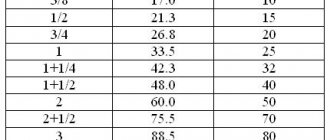
A well-made water supply system will last for many years without breakdowns. However, when installing it, the diameter of the pipes must be selected in accordance with the requirements and construction standards. Therefore, when planning to install plumbing in your home, you need to know how the throughput of a pipe is determined depending on the diameter and pressure of the water. Let's figure out why this is so important and how to take measurements correctly.
Water pipes must have a throughput capacity appropriate to their tasks Source znatoktepla.ru
What methods are available for calculating PS pipes?
PS of pipes is an important parameter, which represents the ability of the pipe to carry the appropriate amount of water in a certain period of time. The PS of the pipeline depends on such a technical indicator as diameter. The higher this parameter, the correspondingly greater amount of water passes through it in the time taken into account.
Diameter, although the main factor, is not the only one. PS also depends on the head pressure in the system, as well as on the type of liquid. The higher the pressure indicator, the greater the value of the indicator in question. To identify the parameter in question, several methods are known, which are called:
- Physical method.
- Tabular method.
- Determination using a program.
Let's take a closer look at what each option is.
How do you measure transfer time
Is the transmission complete when the sender has finished sending the last bit over the wire, or does it also include the time it takes for the last bit to travel to the receiver? Also, does this include the time it takes to receive confirmation from the recipient stating that all data was received successfully and no retransmission is required?
It really depends on what you want to measure
Note that for large transfers, in most cases one extra round trip time is negligible (unless you are communicating with, for example, a probe on Mars)
Physical version of PS determination
The physical method of determining throughput includes carrying out calculations using special formulas. Depending on what type of system is being designed, the calculation formulas will vary. To carry out an independent (physical) calculation of the pipeline PS, the following indicators are taken into account:
- Roughness.
- Inner diameter.
- Pipeline slope.
- Resistance value.
- Degree of overgrowth.
According to the outdated formula, only three main parameters were taken into account: diameter, pressure and roughness. It will be quite problematic for a person who has never encountered this to make the calculation independently.
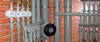
Different types of pipes
Various piping systems are used in a house or apartment. Requirements and calculation methods for them may differ.
For example, the calculation of pipeline capacity in terms of diameter and pressure for a sewer pipe is based on the following parameters:
- Pipeline diameter.
- Average flow rate.
- The hydraulic slope (l) under which the pipes move.
- The degree of filling of the pipe with contents (h/d). When determining this parameter, the concept of hydraulic radius is used.
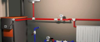
The importance of correct calculations
Calculating water consumption allows you to choose the right pipe material and diameter.
When designing a cottage with two or more bathrooms or a small hotel, you need to take into account how much water the pipes of the selected cross-section can supply. After all, if the pressure in the pipeline drops due to high consumption, this will lead to the fact that it will be impossible to take a normal shower or bath. If the problem arises in a fire, you could lose your home altogether. Therefore, the calculation of the trafficability of highways is carried out even before the start of construction.
It is also important for small business owners to know throughput rates. Indeed, in the absence of metering devices, utility services, as a rule, present an invoice for water consumption to organizations based on the volume passed through the pipe. Knowing the data on your water supply will allow you to control water consumption and not pay extra.
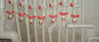
Rules for selecting the size of the main line
To determine the optimal value of the internal diameter of polypropylene pipes, calculations are performed using the initial data as a base:
- The speed at which the medium moves through the pipes;
- Water consumption rate.
If the object is a private house or mansion, then to determine the diameter of the polypropylene products on the basis of which the water supply system will be built, you should use the formula:
D=√((4)-Q-(1000/π∙v))
where v is the speed of the passing flow, m/s (taken from 0.7...2 m/s);
π – Pi number equal to 3.14.
Directly at the stage of selecting pipes for water supply, they most often focus on a diameter of 20 mm.
Calculating the diameter for polypropylene pipes has its own peculiarities when it comes to a multi-story building. Here, at each stage of construction, the parameter value is adjusted. The reason for this is due to differences in the supply of water to a separate apartment, entrance, house, block, microdistrict. The basic rule that is observed here is that as the rate of water consumption increases, the diameter of the main line also increases.
When installing water supply systems for apartment buildings, polypropylene pipes with the following dimensions are most often used:
- when installing risers in five-story buildings - 25 mm;
- when creating wiring inside residential premises - 20 mm;
- when installing risers in buildings with 9 or more floors - 32 mm.
Basic principles of hydraulic calculation
The working medium (liquid, gas, steam) carried by the pipeline being designed, due to its special physical and chemical properties, determines the nature of the flow of the medium in this pipeline. One of the main indicators characterizing the working medium is dynamic viscosity, characterized by the coefficient of dynamic viscosity - μ.
Engineer-physicist Osborne Reynolds (Ireland), who studied the flow of various media, conducted a series of tests in 1880, as a result of which the concept of the Reynolds criterion (Re) was derived - a dimensionless quantity that describes the nature of fluid flow in a pipe. This criterion is calculated using the formula:
The Reynolds criterion (Re) gives the concept of the ratio of inertial forces to viscous friction forces in a fluid flow. The value of the criterion characterizes the change in the ratio of these forces, which, in turn, affects the nature of the carrier flow in the pipeline. It is customary to distinguish the following modes of liquid carrier flow in a pipe depending on the value of this criterion:
- laminar flow (Re<2300), in which the carrier-liquid moves in thin layers that practically do not mix with each other;
- transition mode (2300
- turbulent flow (Re>4000) is a stable mode in which at each individual point of the flow there is a change in its direction and speed, which ultimately leads to equalization of the flow speed throughout the volume of the pipe.
The Reynolds criterion depends on the pressure with which the pump pumps the liquid, the viscosity of the media at operating temperature and the geometric dimensions of the pipe used (d, length). This criterion is a similarity parameter for fluid flow, therefore, using it, it is possible to simulate a real technological process on a reduced scale, which is convenient when conducting tests and experiments.
When carrying out calculations and calculations using equations, part of the given unknown quantities can be taken from special reference sources. Professor, Doctor of Technical Sciences F.A. Shevelev developed a number of tables for accurately calculating the pipe capacity. The tables include the values of parameters characterizing both the pipeline itself (dimensions, materials) and their relationship with the physical and chemical properties of the carrier. In addition, the literature provides a table of approximate values of the flow rates of liquid, steam, and gas in pipes of various sections.
Relay costs
The Internet is a best-effort network, which means that packets will be delivered if possible, but may also be dropped. Packet dropping is adjusted by the transport layer, in the case of TCP; there is no such mechanism for UDP, which means that either the application does not care if some parts of the data are not delivered, or the application itself does the retransmission over UDP.
Retransmission reduces useful performance for two reasons:
A. Some data needs to be sent again, which takes a long time. This introduces a delay that is inversely proportional to the speed of the slowest link in the network between the sender and the receiver (aka the bottleneck). b. Detecting that some data was not delivered requires feedback from the recipient to the sender. Due to propagation delays (sometimes called latency; caused by the finite speed of light in a cable), feedback may only be received by the sender with some delay, further slowing the transmission. In most practical cases, this is the most significant contribution to the additional delay caused by retransmission.
It is clear that if you use UDP instead of TCP and don't care about packet loss, you will of course get better performance. But for many applications, data loss is unacceptable, so this measurement is not meaningful.
There are some applications that use UDP to transfer data. One is BitTorrent, which can use either TCP or a protocol they developed called uTP, which emulates TCP over UDP but aims to be more efficient when using many parallel connections. Another transport protocol implemented over UDP is QUIC, which also emulates TCP and offers multiplexing of multiple parallel transmissions over a single connection and forward error correction to reduce retransmissions.
I'll discuss forward error correction a bit as it relates to your question about throughput. The naive way to implement this is to send each packet twice; in case one gets lost, the other still has a chance to be retrieved
This cuts the number of retransmissions in half, but also halves your useful performance since you are sending redundant data (note that the network or link layer bandwidth remains the same!). In some cases this is normal; especially if the delay is very high, for example on intercontinental or satellite channels
Moreover, there are some mathematical methods where you don't need to send a complete copy of the data; for example, for every n packets you send, you send another redundant packet, which is an XOR (or some other arithmetic operation) of them; if the extra one is lost, it doesn't matter; if one of the n packets is lost, you can recover it based on the redundancy of one and the other n-1. This way, you can configure the overhead introduced by forward error correction for whatever amount of bandwidth you can save.
Selection of the optimal pipeline diameter
Determining the optimal pipeline diameter is a complex production problem, the solution of which depends on a set of various interrelated conditions (technical and economic, characteristics of the working environment and pipeline material, technological parameters, etc.). For example, an increase in the speed of the pumped flow leads to a decrease in the diameter of the pipe that provides the media flow rate specified by the process conditions, which entails a reduction in material costs, cheaper installation and repair of the pipeline, etc. On the other hand, an increase in flow rate leads to a loss of pressure, which requires additional energy and financial costs for pumping a given volume of media.
The value of the optimal pipeline diameter is calculated using the transformed flow continuity equation, taking into account the given media flow:
In hydraulic calculations, the flow rate of the pumped liquid is most often specified by the conditions of the problem. The flow rate of the pumped medium is determined based on the properties of the given medium and the corresponding reference data (see table).
The transformed flow continuity equation for calculating the working diameter of the pipe has the form:
Signal transmission methods
Today, there are three main ways to transmit signals between computers:
- Transmission over radio networks.
- Data transmission via cable.
- Data transmission via fiber optic connections.
Each of these methods has individual characteristics of communication channels, which will be discussed below.
The advantages of transmitting information via radio channels include: versatility of use, ease of installation and configuration of such equipment. As a rule, a radio transmitter is used for receiving and method. It can be a modem for a computer or a Wi-Fi adapter.
The disadvantages of this transmission method include unstable and relatively low speed, high dependence on the presence of radio towers, as well as the high cost of use (mobile Internet is almost twice as expensive as “stationary” Internet).
The advantages of data transmission via cable are: reliability, ease of operation and maintenance. Information is transmitted through electric current. Relatively speaking, a current at a certain voltage moves from point A to point B. A is later converted into information. The wires can withstand temperature changes, bending and mechanical stress very well. The disadvantages include unstable speed, as well as deterioration of the connection due to rain or thunderstorms.
Perhaps the most advanced data transmission technology at the moment is the use of fiber optic cable. Millions of tiny glass tubes are used in the design of the communication channels of the communication channel network. And the signal transmitted through them is a light pulse. Since the speed of light is several times higher than the speed of current, this technology has made it possible to speed up the Internet connection several hundred times.
The disadvantages include the fragility of fiber optic cables. Firstly, they cannot withstand mechanical damage: broken tubes cannot transmit a light signal through themselves, and sudden temperature changes lead to their cracking. Well, the increased background radiation makes the tubes cloudy - because of this, the signal can deteriorate. In addition, the fiber optic cable is difficult to repair if it breaks, so it has to be completely replaced.
The above suggests that over time, communication channels and networks of communication channels are improved, which leads to an increase in data transfer rates.
Methods for calculating pipeline capacity
Before calculating the pipe capacity, you need to know the basic symbols, without which calculations will be impossible:
- External diameter . This indicator is expressed in the distance from one side of the outer wall to the other side. In calculations, this parameter is designated Day. The outer diameter of the pipes is always indicated in the markings.
- Nominal diameter . This value is defined as the diameter of the internal section, which is rounded to whole numbers. When calculating, the nominal diameter is displayed as Dn.
Calculation of pipe permeability can be carried out using one of the methods, which must be selected depending on the specific conditions of pipeline laying:
- Physical calculations . In this case, the pipe capacity formula is used, which allows taking into account each design indicator. The choice of formula is influenced by the type and purpose of the pipeline - for example, sewer systems have their own set of formulas, as do other types of structures.
- Tabular calculations . You can select the optimal cross-country ability using a table with approximate values, which is most often used for arranging wiring in an apartment. The values indicated in the table are quite vague, but this does not prevent them from being used in calculations. The only drawback of the tabular method is that it calculates the throughput of the pipe depending on the diameter, but does not take into account changes in the latter due to deposits, so for pipelines prone to build-up, such a calculation will not be the best choice. To get accurate results, you can use Shevelev’s table, which takes into account almost all factors affecting pipes. This table is perfect for installing highways on individual plots of land.
- Calculation using programs . Many companies specializing in pipeline laying use computer programs in their activities that allow them to accurately calculate not only the pipe capacity, but also a host of other indicators. For independent calculations, you can use online calculators, which, although they have a slightly larger error, are available free of charge. A good option for a large shareware program is “TAScope”, and in the domestic space the most popular is “Hydrosystem”, which also takes into account the nuances of pipeline installation depending on the region.
Factors affecting Internet speed
As you know, the final speed of the Internet depends on the bandwidth of the communication channel. The speed of information transfer is also affected by:
Connection methods.
Radio waves, cables and fiber optic cables. The properties, advantages and disadvantages of these connection methods were discussed above.
Server load.
The busier the server is, the slower it receives or transmits files and signals.
External interference.
Interference has the greatest impact on connections created using radio waves. This is caused by cell phones, radios, and other radio receivers and transmitters.
Status of network equipment.
Of course, connection methods, the state of servers and the presence of interference play an important role in ensuring high-speed Internet. However, even if the above indicators are normal, and the Internet speed is low, the problem is hidden in the computer’s network equipment. Modern network cards are capable of supporting Internet connections at speeds of up to 100 Mbit per second. Previously, cards could provide maximum throughput of 30 and 50 Mbps, respectively.
Water pipe capacity
Water pipes are the most commonly used pipes in a home. And since they are subject to a large load, calculating the throughput of the water main becomes an important condition for reliable operation.
Torricelli's Law
The formula of the Italian mathematician and physicist Torricelli uses the law of conservation of energy for ideal liquids and gases.
The scientist obtained a relationship connecting the speed of the molecule and the height of the liquid column (pressure):
U=√2gH, where U is the speed of movement of a molecule of a substance, g is the acceleration of gravity, H is pressure.
Knowing the fluid speed and standard flow rate, you can determine the required cross-sectional area S of the pipe:
S=Q /V, where Q is the flow rate determined according to SNiP 2.04.01-85*.
The area of a circle is related to the diameter by the ratio S = pD²/4, from which:
D=2√(S/p)=2√(Q/(Up)), where p — 3.14.
Torricelli's formula is valid for ideal liquids with zero viscosity or incompressible gases. In addition, the calculations do not take into account the roughness of pipes, the length of communications and other parameters that cause hydraulic losses. The result obtained is very approximate and can be used if the diameter is taken to be 20-30% larger than the calculated one.
Pipe patency depending on diameter
Diameter is not the most important parameter when calculating the patency of a pipe, but it also affects its value. The larger the internal diameter of the pipe, the higher the permeability, and also the lower the chance of blockages and plugs. However, in addition to the diameter, it is necessary to take into account the coefficient of friction of water on the pipe walls (tabular value for each material), the length of the line and the difference in liquid pressure at the inlet and outlet. In addition, the number of elbows and fittings in the pipeline will greatly influence the flow rate.
Table of pipe capacity by coolant temperature
The higher the temperature in the pipe, the lower its throughput, since the water expands and thereby creates additional friction. For plumbing this is not important, but in heating systems it is a key parameter.
There is a table for calculations of heat and coolant.
Table 5. Pipe throughput depending on the coolant and heat transfer Pipe diameter, mm Heat throughput By coolantWaterSteamWaterSteamGcal/h/h15 25 38 50 75 100 125 150 200 250 300 350 400 450 500 600 700 800 900 1000
| 0,011 | 0,005 | 0,182 | 0,009 |
| 0,039 | 0,018 | 0,650 | 0,033 |
| 0,11 | 0,05 | 1,82 | 0,091 |
| 0,24 | 0,11 | 4,00 | 0,20 |
| 0,72 | 0,33 | 12,0 | 0,60 |
| 1,51 | 0,69 | 25,0 | 1,25 |
| 2,70 | 1,24 | 45,0 | 2,25 |
| 4,36 | 2,00 | 72,8 | 3,64 |
| 9,23 | 4,24 | 154 | 7,70 |
| 16,6 | 7,60 | 276 | 13,8 |
| 26,6 | 12,2 | 444 | 22,2 |
| 40,3 | 18,5 | 672 | 33,6 |
| 56,5 | 26,0 | 940 | 47,0 |
| 68,3 | 36,0 | 1310 | 65,5 |
| 103 | 47,4 | 1730 | 86,5 |
| 167 | 76,5 | 2780 | 139 |
| 250 | 115 | 4160 | 208 |
| 354 | 162 | 5900 | 295 |
| 633 | 291 | 10500 | 525 |
| 1020 | 470 | 17100 | 855 |
Table of pipe capacity depending on coolant pressure
There is a table describing the capacity of pipes depending on pressure.
Table 6. Pipe throughput depending on the pressure of the transported liquid Flow throughput Pipe diameter 15 mm 20 mm 25 mm 32 mm 40 mm 50 mm 65 mm 80 mm 100 mm Pa/m - mbar/m less than 0.15 m/s 0.15 m/s 0.3 m/s 90 .0 - 0.900 92.5 - 0.925 95.0 - 0.950 97.5 - 0.975 100.0 - 1.000 120.0 - 1.200 140.0 - 1.400 160.0 - 1.600 180.0 - 1.800 200.0 - 2.000 220 .0 — 2.200 240.0 — 2.400 260.0 — 2.600 280.0 — 2.800 300.0 — 3.000
| 173 | 403 | 745 | 1627 | 2488 | 4716 | 9612 | 14940 | 30240 |
| 176 | 407 | 756 | 1652 | 2524 | 4788 | 9756 | 15156 | 30672 |
| 176 | 414 | 767 | 1678 | 2560 | 4860 | 9900 | 15372 | 31104 |
| 180 | 421 | 778 | 1699 | 2596 | 4932 | 10044 | 15552 | 31500 |
| 184 | 425 | 788 | 1724 | 2632 | 5004 | 10152 | 15768 | 31932 |
| 202 | 472 | 871 | 1897 | 2898 | 5508 | 11196 | 17352 | 35100 |
| 220 | 511 | 943 | 2059 | 3143 | 5976 | 12132 | 18792 | 38160 |
| 234 | 547 | 1015 | 2210 | 3373 | 6408 | 12996 | 20160 | 40680 |
| 252 | 583 | 1080 | 2354 | 3589 | 6804 | 13824 | 21420 | 43200 |
| 266 | 619 | 1151 | 2486 | 3780 | 7200 | 14580 | 22644 | 45720 |
| 281 | 652 | 1202 | 2617 | 3996 | 7560 | 15336 | 23760 | 47880 |
| 288 | 680 | 1256 | 2740 | 4176 | 7920 | 16056 | 24876 | 50400 |
| 306 | 713 | 1310 | 2855 | 4356 | 8244 | 16740 | 25920 | 52200 |
| 317 | 742 | 1364 | 2970 | 4356 | 8566 | 17338 | 26928 | 54360 |
| 331 | 767 | 1415 | 3076 | 4680 | 8892 | 18000 | 27900 | 56160 |
Table of pipe capacity depending on diameter (according to Shevelev)
The tables of F.A. and A.F. Shevelev are one of the most accurate tabular methods for calculating the throughput of a water pipeline. In addition, they contain all the necessary calculation formulas for each specific material. This is a lengthy piece of information that is most often used by hydraulic engineers.
The tables take into account:
- pipe diameters – internal and external;
- wall thickness;
- service life of the water supply system;
- line length;
- purpose of pipes.
Sewerage
When arranging pipelines for the removal of wastewater, it is necessary to pay special attention to the arrangement of a riser made of polypropylene structures.
| Angle of connection of branches to the riser (degrees) | Indicator of the outer diameter of interfloor bends (mm) | Riser diameter value (mm) | |
| 110 | 50 | ||
| 87.50 | 110.00 | 3.60 | – |
| 60.00 | 110.00 | 5.40 | – |
| 45.00 | 110.00 | 5.90 | – |
| 87.50 | 50.00 | 5.20 | 0.66 |
| 60.00 | 50.00 | 7.80 | 1.00 |
| 45.00 | 50.00 | 8.40 | 1.07 |
| 87.50 | 40.00 | 5.50 | 0.76 |
| 60.00 | 40.00 | 8.25 | 1.14 |
| 45.00 | 40.00 | 8.95 | 1.23 |
When installing unventilated risers made of polypropylene structures, it is necessary to use the data presented below.
| Throughput values (milliliters/second) | Connection angle of interfloor branches (degrees) | Riser height value (meters) | ||||
| Outer diameter of the channel / value of the internal cross-section of the interfloor outlet (mm) | ||||||
| 110/110 | 110/50 | 110/40 | 50/50 | 50/40 | ||
| 1100 | 850 | 800 | 480 | 420 | 87.50 | 9.00 |
| 1120 | 1000 | 950 | 550 | 470 | 60.00 | 9.00 |
| 1150 | 1100 | 1040 | 600 | 500 | 45.00 | 9.00 |
| 1400 | 1000 | 960 | 480 | 420 | 87.50 | 8.00 |
| 1550 | 1200 | 1150 | 550 | 470 | 60.00 | 8.00 |
| 1700 | 1300 | 1200 | 600 | 500 | 45.00 | 8.00 |
| 1600 | 1200 | 1070 | 480 | 420 | 87.50 | 7.00 |
| 1800 | 1400 | 1300 | 550 | 470 | 60.00 | 7.00 |
| 2000 | 1550 | 1420 | 600 | 500 | 45.00 | 7.00 |
| 1800 | 1500 | 1420 | 480 | 420 | 87.50 | 6.00 |
| 2100 | 1700 | 1670 | 550 | 470 | 60.00 | 6.00 |
| 2350 | 1850 | 1770 | 600 | 500 | 45.00 | 6.00 |
| 2400 | 1850 | 1770 | 480 | 420 | 87.50 | 5.00 |
| 2700 | 2050 | 1950 | 550 | 470 | 60.00 | 5.00 |
| 3000 | 2250 | 2100 | 600 | 500 | 45.00 | 5.00 |
| 3000 | 2400 | 2300 | 480 | 420 | 87.50 | 4.00 |
| 3400 | 2700 | 2600 | 550 | 470 | 60.00 | 4.00 |
| 3700 | 3000 | 2800 | 600 | 500 | 45.00 | 4.00 |
| 4100 | 3300 | 3200 | 650 | 580 | 87.50 | 3.00 |
| 4600 | 3700 | 3500 | 740 | 660 | 60.00 | 3.00 |
| 5000 | 4000 | 3800 | 800 | 720 | 45.00 | 3.00 |
| 5900 | 4950 | 4700 | 970 | 880 | 87.50 | 2.00 |
| 6400 | 5500 | 5100 | 1050 | 910 | 60.00 | 2.00 |
| 6800 | 5800 | 5400 | 1120 | 960 | 45.00 | 2.00 |
| 9500 | 8400 | 8000 | 1650 | 1440 | 87.50 | 1.00 |
| 10100 | 9100 | 8500 | 1700 | 1520 | 60.00 | 1.00 |
| 10600 | 9500 | 8800 | 1800 | 1600 | 45.00 | 1.00 |
To calculate the parameter under consideration for sewer mains, it is necessary to resort to other calculation methods. In this case, the type of channel plays a big role. If we are talking about non-pressure systems, use the Lukin tables, which can be downloaded from our website.
With their help, the coefficient in question is calculated for products of a given size.
When creating pressure circuits, the calculation will be easier. The main thing is to accurately set the maximum contour filling parameter and the average speed of the carrier.
The easiest way to do this is using a table of the capacity of polypropylene pipes.
Methods for calculating pipeline capacity
Hydraulic calculations are carried out in order to select system elements with optimal characteristics to ensure uninterrupted operation, reduce operating costs and reduce equipment wear.
Hydraulic calculation of the pipeline
Calculations are carried out using Shevelev tables according to the following algorithm:
- The required flow rate Q and the optimal speed of the medium in each section are set.
- The diameter of the pipe is selected, and the pressure loss along the length is determined.
- The procedure is repeated for all sections.
- The specific value of pressure loss per 1 linear line is found. m.
- All other losses from suction, local resistance, etc. are summed up. The resulting value must be less than or equal to the pump power.
- Based on the technical characteristics of the equipment, the flow rate Q of the pump is determined.
- Q and Qpump are compared. If the values are approximately equal, the pump is selected correctly. If not, you need to set new parameters and calculate again.
Calculation of sewer pipe capacity
The diameter and angle of inclination are set at which wastewater flows randomly, and the system constantly cleans itself (from 0.005 to 0.035 depending on the cross-section):
The degree of filling of the pipe according to the standard is 0.6-0.8 and also depends on the diameter:
Dependence of filling on pipe diameter
Using the Lukin tables, it is clarified whether the selected diameter corresponds to the specified parameters. If there are deviations, the cross section needs to be changed up/down. For more accurate calculations, graphs, formulas and correction factors are used.
Calculation of gas pipeline capacity
In accordance with the parameters of the designed network, the diameters of the pipes at the inlet and outlet of the gas distribution system are set. Then, comparing the values in the tables, they find a ratio in which the conditions are maximally met.
How to calculate chimney parameters
The main characteristics that are determined during the calculations are the length of the chimney pipe and its working cross-section. If the parameters are incorrectly selected, toxic substances are not removed from the combustion chamber and penetrate into the room.
When designing, the standards SP 7.13130.2013 and SNiP III-G.11-62 are used. Although the latest regulation is considered ineffective, it contains recommendations specifically related to chimneys.
Complex industrial devices are calculated in professional bureaus; for home ovens, a simpler method is used.
Example:
- The speed of smoke movement is set to U=2 m/s.
- In an hour, approximately B = 6 kg of wood with a humidity of 20-25% burns in the firebox.
- Temperature of heated smoke T=140°.
The volume of emanating smoke is determined by the formula:
Vgas = (B x Vfuelx (1+T/273))/3600, m3/s, where Vfuel is the volume of air required to burn 1 kg of wood. In this case it is 10 m³, for a brown corner 12 m³, for a stone corner 17 m³.
Vgas=6x10x(1+140/273))/3600=0.025 m³/s.
Knowing the volume of outgoing gas and its speed, you can find the cross-sectional area of the chimney pipe:
S=Vgas/U=0.025/2=0.0126 m².
The diameter is determined by the geometric formula:
D=2√(S/p)=2√(0.0126/3.14)=0.126 m = 126 mm.
The nearest pipe diameter, rounded up, is 150 mm.
The main characteristics that are determined during the calculations are the length of the chimney pipe and its working cross-section. If the parameters are incorrectly selected, toxic substances are not removed from the combustion chamber and penetrate into the room.
The length of the chimney to ensure normal draft is selected according to SP 7.13130.2013, which standardizes the height from the head to the stove grate, the roof ridge, as well as the distance to surrounding large objects.
Nuances of the heating circuit
To design a heating system with high quality, you need to use reinforced polypropylene pipes. It is very important that they comply with GOST R 52134-2003. Such products are best protected from deformation. In addition, they do not significantly change their linear dimensions under the influence of hot water.
To arrange the heating circuit, it is advisable to use structures reinforced with aluminum foil or fiberglass. Each version of the listed products has its own strengths and weaknesses. Channels reinforced with fiberglass are more convenient, since during installation there is no need to remove the aluminum layer.
To calculate what diameter pipes to use, you need to consider:
- temperature difference between the supply and return circuits;
- fluid velocity indicator (standard - 0.6 m/s);
- room size.
Inner and outer diameter, wall thickness, radius
Pipes are a specific product. They have an internal and external diameter, since their wall is thick, its thickness depends on the type of pipe and the material from which it is made. Technical specifications often indicate the outer diameter and wall thickness.
Pipe inner and outer diameter, wall thickness
Having these two values, it is easy to calculate the internal diameter - subtract twice the wall thickness from the external one: d = D - 2*S. If you have an outer diameter of 32 mm, a wall thickness of 3 mm, then the inner diameter will be: 32 mm - 2 * 3 mm = 26 mm.
If, on the contrary, there is an internal diameter and wall thickness, but an external one is needed, we add double the stack thickness to the existing value.
With radii (denoted by the letter R) it is even simpler - this is half the diameter: R = 1/2 D. For example, let’s find the radius of a pipe with a diameter of 32 mm. Just divide 32 by two, we get 16 mm.
Vernier caliper measurements are more accurate
What to do if there are no technical data for the pipe? To measure. If special accuracy is not needed, a regular ruler will do; for more accurate measurements, it is better to use a caliper.
Shipping charges
The Internet is a best-effort network, which means that packets will be delivered if possible, but may also be dropped. Packet droplets are corrected by the transport layer, in the case of TCP; there is no such mechanism for UDP, which means that either the application does not care if some parts of the data are not delivered, or the application implements retransmission directly on top of UDP.
Retransmission reduces consumption for two reasons:
A. Some data needs to be sent again, which takes time. This introduces a delay that is inversely proportional to the speed of the slowest link in the network between the sender and the receiver (aka the bottleneck node). b. Detecting that some data was not delivered requires feedback from the recipient to the sender. Due to propagation delays (sometimes called latency, caused by the finite speed of light in the cable), feedback can only be received by the sender with some delay, further slowing down the transmission. In most practical cases, this is the largest contribution to the additional delay caused by retransmission.
Obviously, if you use UDP instead of TCP and don't care about packet loss, you will of course get better performance. But for many applications, data loss cannot be tolerated, so this measurement is meaningless.
There are some applications that use UDP to transfer data. One of them is BitTorrent, which can use either TCP or a protocol they created called uTP, which emulates TCP over UDP but tends to use many parallel connections more efficiently. Another transport protocol implemented over UDP is QUIC, which also emulates TCP and offers multiplexing of multiple parallel transmissions over a single connection and forward error correction to reduce retransmissions.
I'll discuss forward error correction a bit, since it's related to your question about throughput. The naive way to implement it is to send each packet twice; in case someone gets lost, the other still has a chance to get
This reduces the number of retransmissions by up to half, but also halves your revenue since you are sending redundant data (note that the network or link level bandwidth remains the same!). In some cases this is normal; especially if the latency is very high, for example on intercontinental or satellite channels
Also, there are some math methods where you don't have to send a complete copy of the data; for example, for every n packets you send, you send another reduntant, which is an XOR (or some other arithmetic operation) of them; if the extra one is lost, it doesn't matter; if one of the n packets is lost, you can recover it based on the redundant one and the other n-1. This way you can tune the overhead caused by forward error correction to whatever amount of bandwidth you can spare.
Calculation of pipe surface area
The pipe is a very long cylinder, and the surface area of the pipe is calculated as the area of the cylinder. For calculations, you will need a radius (internal or external - depends on what kind of surface you need to calculate) and the length of the segment that you need.
Formula for calculating the side surface of a pipe
To find the lateral area of the cylinder, we multiply the radius and length, multiply the resulting value by two, and then by the number “Pi”, we obtain the desired value. If desired, you can calculate the surface of one meter, which can then be multiplied by the desired length.
For example, let's calculate the outer surface of a piece of pipe 5 meters long, with a diameter of 12 cm. First, let's calculate the diameter: divide the diameter by 2, we get 6 cm. Now all values must be reduced to the same units of measurement. Since the area is calculated in square meters, we convert centimeters to meters. 6 cm = 0.06 m. Next, we substitute everything into the formula: S = 2 * 3.14 * 0.06 * 5 = 1.884 m2. If you round it up, you get 1.9 m2.
What is a bit How is bit rate measured?
Bit rate is a measurement of connection speed. Calculated in bits, the smallest units of information storage, per 1 second. It was inherent in communication channels in the era of the “early development” of the Internet: at that time, text files were mainly transmitted on the global web.
Currently, the basic unit of measurement is 1 byte. It, in turn, is equal to 8 bits. Beginner users very often make a grave mistake: they confuse kilobits and kilobytes. This is where the confusion arises when a channel with a bandwidth of 512 kbps does not live up to expectations and produces a speed of only 64 KB/s. To avoid confusion, you need to remember that if bits are used to indicate speed, then the entry will be made without abbreviations: bit/s, kbit/s, kbit/s or kbps.
Weight calculation
When calculating the weight of a pipe, everything is simple: you need to know how much a linear meter weighs, then multiply this value by the length in meters. The weight of round steel pipes is in reference books, since this type of rolled metal is standardized. The weight of one linear meter depends on the diameter and wall thickness. One point: the standard weight is given for steel with a density of 7.85 g/cm2 - this is the type recommended by GOST.
Round Steel Pipe Weight Table
In table D - outer diameter, nominal diameter - inner diameter, And one more important point: the weight of ordinary rolled steel is indicated; galvanized steel is 3% heavier.
Weight table for profiled square pipe
What determines the permeability of a pipe?
The permeability of pipe sections is a metric value that characterizes the volume of liquid passed through the pipeline over a certain time interval. This indicator depends on the material used in the production of pipes.
Plastic pipelines maintain almost the same permeability throughout the entire operational period. Plastic, compared to metal, does not rust, so the lines do not become clogged for a long time.
For metal models, throughput decreases year after year. As the pipes rust, the inner surface gradually peels off and becomes rough. Because of this, much more plaque forms on the walls. Hot water pipes in particular clog quickly.
In addition to the material of manufacture, cross-country ability also depends on other characteristics:
- Pipeline lengths. The greater the length, the lower the flow velocity due to the influence of friction, and the pressure decreases accordingly.
- Pipe diameter. The walls of narrow highways create more resistance. The smaller the cross-section, the worse the ratio of flow velocity to internal area will be over a section of a fixed length. Wider pipes move water faster.
- Presence of turns, fittings, adapters, taps. Any shaped parts slow down the movement of water flows.
How to calculate cross-sectional area
Formula for finding the cross-sectional area of a round pipe
If the pipe is round, the cross-sectional area should be calculated using the formula for the area of a circle: S = π*R2. Where R is the radius (internal), π is 3.14. In total, you need to square the radius and multiply it by 3.14.
For example, the cross-sectional area of a pipe with a diameter of 90 mm. We find the radius - 90 mm / 2 = 45 mm. In centimeters this is 4.5 cm. We square it: 4.5 * 4.5 = 2.025 cm2, substitute it into the formula S = 2 * 20.25 cm2 = 40.5 cm2.
The cross-sectional area of a profiled pipe is calculated using the formula for the area of a rectangle: S = a * b, where a and b are the lengths of the sides of the rectangle. If we consider the cross-section of the profile to be 40 x 50 mm, we get S = 40 mm * 50 mm = 2000 mm2 or 20 cm2 or 0.002 m2.
Overhead due to headers
Each layer in the network adds a header to the data, which introduces some overhead due to its transmission time. Additionally, the transport layer breaks your data into segments; this is because the network layer (as in IPv4 or IPv6) has a maximum packet MTU size, typically 1500 V on Ethernet networks. This value includes the size of the network layer header (for example, the IPv4 header, which is variable length, but typically 20 B long) and the transport layer header (for TCP, it is also variable length, but typically 40 B long). This results in a maximum MSS segment size (number of bytes of data, excluding headers, in one segment) of 1500 - 40 - 20 = 1440 bytes.
Thus, if we want to send 6 KB of application layer data, we must split it into 6 segments, 5 of 1440 bytes each and one of 240 bytes. However, at the network layer, we end up sending 6 packets, 5 of 1500 bytes each and one of 300 bytes, for a total of 6.3 kB.
What I didn't consider here is the fact that the link layer (as in Ethernet) adds its own header and possibly also a suffix, which adds additional overhead. For Ethernet it is 14 bytes for the Ethernet header, optionally 4 bytes for the VLAN tag, then a CRC of 4 bytes and a space of 12 bytes, for a total of 36 bytes per packet.
If you count a fixed speed link, say 10 Mbps, depending on what you're measuring, you'll get a different throughput. Typically you want one of these:
- Good performance, that is, application layer throughput if you want to measure application performance. In this example, you divide 6 kB by the duration of the transfer.
- Communication bandwidth, if you want to measure network performance. In this example, you divide 6 kB + TCP overhead + IP overhead + Ethernet overhead = 6.3 kB + 6 * 36 B = 6516 B by transfer duration.
Defectiveness of products - how to calculate the diameter of a pipe without errors?
When installing a sewer, water or gas pipeline, it is worth considering that all pipes have a permissible deviation standard. Parameters such as length, outer diameter and wall thickness may not be accurate. All permissible deviations are regulated by GOST and, if necessary, manufacturers must provide certificates and documents. We will not dwell in detail on how to select the diameter of the pipe, taking into account all kinds of defects. We note only deviations from the norm permitted by GOST.
All pipe products at large construction sites undergo mandatory control procedures. Certificates are verified and must contain a number of parameters, such as chemical analysis of the material and test results. The presence of markings on the pipes is also monitored, which should indicate the main characteristics, date of manufacture and manufacturer. Often the marking is applied to the surface of one of the ends of the product.
For pipes used in residential construction (with a diameter of less than 200 mm), the maximum deviation can be 1.5 mm.
The permissible deviations in the diameters of large pipes are approximately 0.7%, and accurate measurements are carried out using special ultrasonic installations. The length of the product is the indicator that can deviate from the norm more than any other. According to GOST, pipe products of the second accuracy class may have a deviation of ± 100 mm. The permissible standard for first class pipes is ± 15 mm. The wall thickness may also differ from the declared one: deviations can be up to ± 5%.
In addition, there is such a defect as the curvature of the product: its permissible value is no more than 0.15% of the length. For example, for a pipe 1 m long, the permissible deviation is 1.5 mm. For pipes with an oval cross-section, dimensional inaccuracies are also acceptable. According to GOST, the permissible deviation of the ovality parameter should not exceed 1% of that declared by the manufacturer. To check this deviation, you need to know how the diameter of a pipe with an oval cross-section is measured: it is the arithmetic mean between the largest and smallest section width. The ovality index itself can be determined as follows:
- measure the largest and smallest section width;
- subtract the difference between them;
- divide the resulting value by the nominal diameter;
To accurately determine the ovality parameter, a special device is used - a bore gauge.
Features of installation work
The connection of polypropylene elements is carried out by welding on a special device. With its help, individual fragments are heated to a given temperature, and then joined together to form a solid product.
The connection of polypropylene and metal elements is carried out using fittings with threaded inserts. Sealing is ensured using Teflon tape and a number of other sealants.
Attention! Thread cutting on finished products is unacceptable! Installation should be carried out using fittings produced by the same manufacturer.
To form a quality connection you should:
- carefully inspect all connected elements to eliminate contamination and damage;
- perform work at temperatures above 5° C. Bending – above 15° C;
- maximum bending radius, depending on the diameter of the PP pipes;
- mount system elements on a fixed support only in exceptional cases, since it does not allow compensatory displacement;
- When fastening, thermal expansion must be taken into account.
You can view the details of the installation work in the following video:
What is the power in the DHW and cold water systems?
The water pressure in multi-storey buildings connected to the central water supply network is not constant.
It depends on factors such as the number of storeys in the building or the time of year - so in the summer season, especially in multi-storey buildings, the lack of cold water becomes especially noticeable, which at this time is used for watering house or garden plots.
Municipal services in practice try to keep the level at an average of 3-4 atmospheres, although not always successfully. The minimum indicators at which the pipeline of a house can function (for both cold water supply and hot water supply) are 0.3 bar per floor.
The pressure of hot and cold water supply is slightly different in favor of the latter (a difference of up to 25% is allowed).
This is explained simply - cold water is used more actively, since it is needed for the functioning of the sewage system. Therefore, the maximum indicators for cold water supply will be 6 atmospheres, and for hot water supply – 4.5 atmospheres.
Information transfer rate in a discrete communication system
In a discrete communication system, in the absence of interference, the information at the output of the communication channel (PI channel) completely coincides with the information at its input, therefore the speed of information transfer is numerically equal to the productivity of the message source:
.
(5.1)
In the presence of interference, part of the source information is lost and the information transmission speed is lower than the source performance. At the same time, information about interference is added to the message at the channel output (Fig. 12).
Therefore, in the presence of interference, it is necessary to take into account at the channel output not all the information provided by the source, but only mutual information:
bps (5.2)
Based on formula (5.1) we have
or
, (5.3)
where H ( x ) _
source performance
;
H ( xy ) _ _
unreliability of the channel (loss) per unit of time;
H ( y ) _
entropy of the output message per unit time;
H ( yx ) _ _
=
H '( n )
– entropy of interference (noise) per unit time.
Communication channel capacity
(information transmission channel)
C
is the maximum possible speed of information transmission over the channel
.
(5.4)
To achieve the maximum, all possible output sources and all possible encoding methods are taken into account.
Thus, the capacity of a communication channel is equal to the maximum performance of the source at the input of the channel, fully consistent with the characteristics of this channel, minus the loss of information in the channel due to interference.
In a channel without interference C = max H ( x )
, since
H ( x y )=0
.
When using a uniform code with base k
, consisting of
n
elements of duration
e
, in a channel without interference
,
at k
=2
bps. (5.5)
To effectively use the channel's capacity, it must be coordinated with the source of information at the input. Such coordination is possible both for communication channels without interference and for channels with interference based on two theorems proved by K. Shannon.
Theorem 1 (for a communication channel without interference):
If the message source has entropy
H (bits per symbol) and the communication channel has capacity C (bits per second), then it is possible to encode messages in such a way as to transmit information through the channel with an average speed arbitrarily close to the value of C , but not surpass it.
K. Shannon also proposed a method of such coding, which was called statistical or optimal coding. The idea of such encoding was later developed in the works of Fano and Huffman and is now widely used in practice for “message compression.”
What indicators are considered the norm (according to GOST, SNiP)?
Water supply is regulated by the following regulations:
- SNiP2.04.02-84;
- SNiP2.04.02-85;
- GOST 356-80;
- Decree of the Government of the Russian Federation No. 354.
In accordance with these documents, the free pressure in the water supply network at the entrance to the building directly depends on its number of storeys - for one-story buildings this figure is equal to 1 atmosphere, which corresponds to 10 meters of water pressure.
In multi-storey buildings this value increases by 4 meters for each floor of the building. At night, the incoming pressure can be reduced to 3 meters.
The pressure of cold water should be in the range from 0.3 to 6 atmospheres, hot - from 0.3 to 4.5.
Attention. According to clause 2.28 of SNiP 2.04.02-84, the maximum pressure at the entrance to the water supply network of a multi-storey building cannot exceed 60 meters of water column (6 atmospheres). Otherwise, you should install pressure regulators or use zoning of the water supply network.
Classification of propylene pipes according to the composition of raw materials
- PPR pipes. This category usually includes structures that are created using a static polypropylene copolymer, which is distinguished by the presence of a crystalline molecular structure. These products perfectly withstand temperatures in the range from - 170 to + 1400 degrees Celsius. At the same time, they cope well with shock loads, which is why they are widely used when carrying out work on the construction of sewerage, plumbing and heating. These products are most often used in the construction of residential buildings. If we talk about their sizes, they are about 16–110 mm. The signs of their classification may include, first of all, a parameter such as pressure.
- PPH pipes. The material used to create these structures is raw materials, which are mixed with modifying additives. The latter can be antistatic agents, fire retardants, and nucleators. The effect of introducing the latter into the composition provides an increase in the impact strength of the polymer. Using similar structures, external cold water supply systems, as well as ventilation and drainage systems are erected. At the same time, they do not seem to be the best option for creating heating systems based on them. The reason for this is due to the low melting point. The diameter of structures in this category is usually quite large, since most of them are used in the construction of industrial sewerage and drainage systems.
- PPB pipes. If we consider the structure of this material, then its basis is formed by homopolymer micromolecules having different structures, compositions and locations. It is the special molecular structure that is responsible for the property of this product, which is its high resistance to impact. For this reason, they are most often used in the installation of underfloor heating systems and cold water supply.
- PPs pipes. This category is represented by polymers of the highest class, the main feature of which is a unique molecular composition. The advantages include high resistance to loads and heat. They also have high wear resistance and strength characteristics. The diameter of structures created on the basis of such polypropylene is about 20–1200 mm. Most of them are used in the installation of ventilation systems, hot and cold water supply, and heating.
How to find out power: step-by-step instructions
The most accurate way to determine the pressure of a water supply system can be a built-in pressure gauge - it is installed at the entrance to the internal network immediately after the shut-off valves with a filter.
If such equipment is not installed, then you can make a portable analogue yourself.
For this you will need:
- pressure gauge up to 6 atmospheres;
- threaded extension;
- adapter (if necessary);
- fumlenta;
- adjustable wrench.
Work order:
- A threaded extension is attached to the pressure gauge, onto which an adapter is attached (if necessary). To ensure the accuracy of measurements, the joints are sealed using fume tape.
- Disconnect the watering can from the shower hose and screw on the previously prepared pressure gauge; the connection is sealed with fume tape.
- Fully open the shower valve and take readings from the pressure gauge.
Reference. During testing, for the accuracy of readings, you cannot use other plumbing fixtures: washing machine, sink, toilet, etc.
This method is the most accurate, however, if you urgently need to know the pressure, but there is no pressure gauge at hand, then you can use another, albeit less accurate, method: determining the pressure by water flow.
You will need:
- three-liter jar;
- stopwatch.
Measurement procedure:
- A 3-liter container is placed under the tap, which is previously opened to full capacity.
- At the same time, time is recorded on a stopwatch and how long it will take to fill the container.
- The obtained time is checked against the tabular data and the pressure is set.
Table: dependence of pressure on water flow:
The video clearly shows how you can measure water pressure yourself:
What data will be required:
- Material for making pipes.
- Pipeline length.
- and its shape.
- Number of liquid collection points.
- Slope of the structure.
- Presence of systemic pressure.
- Installation method.
For a more accurate calculation, you will have to take into account all individual nuances. There are no universal methods; for many projects it is necessary to take into account the pipe roughness coefficient, resistance to water flow, and the rate of “overgrowing”.
The diameter of the pipes can be called the most important indicator in the calculations. If the system is installed from pipes of smaller diameter than required, this leads to a number of unpleasant moments.
- Increased load and pressure in the system leads to rapid wear of the system, frequent breakthroughs and repairs.
- The “buzz” of the system is extraneous noise caused by excessive pressure on the pipe walls.
- The impossibility of simultaneous water intake from several points - in other words, when you open the tap at one point, for example, in the bathroom, the water no longer reaches.
- The maximum possible water speed in the pipe is 2 m/sec. This condition does not apply to industrial structures with installations that artificially increase intra-system pressure.
- When calculating, take into account the consumption of all water intake points simultaneously. The average throughput is 6 l/sec; the dial speed of a washing machine or dishwasher can be found in the operating instructions. If the system is not used at full intensity, then the resulting indicator is reduced by a third.
- Diameter 20 mm – for water supply systems up to 10 meters long.
- Diameter 25 mm – system from 10 to 30 meters.
- Diameter 32 mm – system over 30 meters.
- Diameter 50 mm – system over 50 meters.
- Diameter 100 mm - used in industrial or long pipeline systems with a large number of water intake points.
The next important indicator is system pressure. When installing a gravity water supply system, the use of smaller diameters is allowed. If there is constant pressure in the system, for example, city water supply, you need to take its indicator into account when calculating. If this indicator is ignored, the pipes will “hum” and vibrate, which will lead to deformation of the connecting joints and render the system unusable.
If he talks about metal, then steel pipes are also used for water pipes. For intra-apartment or intra-house wiring, formulas and special calculations are used extremely rarely.
Practice-tested diameters are most often used:
- Water pipe distribution 15 mm.
- Installation of risers 25, 32, 40 mm.
Here you need to take into account the internal diameter, which can vary by 1-3 mm depending on the manufacturer.
The new one is practically not inferior in characteristics to its plastic counterparts, but after a year its throughput drops significantly. This is explained by the appearance of growths on the inner walls, and, as a consequence, a decrease in diameter and an increase in resistance to water flow.
However, the use of metal pipes is justified when it comes to constant high system pressure, for example, during steam heating installations, industrial projects or in areas with a high risk of explosion.
Every year, progressive manufacturers bring more convenient and high-quality materials to the market, optimizing their characteristics to meet consumer requirements.
Pipes are distinguished from:
- Polyethylene and cross-linked polyethylene (PEX).
- Metal-polymers or metal-plastic - a combination of PEX with metal.
- Polyvinyl chloride (PVC).
- Polypropylene (PP) and its varieties depending on.
As for the throughput of pipes made of these materials, it is significantly higher than that of metal pipes, taking into account the service life. All of the above types of pipes have significant advantages over metal ones.
- Durability - with proper use, the service life of plastic pipes can reach 50 years, metal needs to be replaced after a maximum of 20 years of use.
- Smooth inner surface of the pipes - the original characteristics and inertness of the polymers do not allow the system to become overgrown, are not damaged in the presence of mechanical particles in the water, and are not susceptible to corrosion and aggressive chemicals.
- Simplicity of installation and repair - the light weight of the structure and the dismountable fitting allow you to handle network maintenance yourself.
- Significant savings - plastic materials and their transportation are several times cheaper than metal.
The only drawback is that they cannot withstand long-term operation at pressures of more than 10 atmospheres and extremely high temperatures.
To calculate the throughput of a new pipe, regardless of the material of manufacture, you can use the following table:
How to plug a pipe with pressurized water?
Putting a plug on a pipe is not a tricky thing if you do it without pressure.
But when the water cannot be turned off, many will think that it is impossible to do so. However, it is not.
It will not be possible to install a regular plug , since the strong pressure will not even make it possible to attach it to the thread.
But if you use a regular water tap instead, everything will work out.
The method is to switch the tap that will plug the pipe into open mode - water will pass through it and thereby make it possible to attach it to the threads of the pipe. As soon as the plug valve is attached and tightened a few turns, it can be closed.
Before work, you need to make sure that nothing will interfere with the work , and also prepare a container for collecting water and a rag for cleaning (so as not to drown your neighbors).
This method can be used even if the pipe to be plugged is without a thread - then you need to put a flexible hose on the plug valve that fits onto the pipe.
The tap, as in the first case, must be fully opened, and the hose must be placed on the pipe - it must be secured with one or two clamps. After this, you can finally turn off the water.
Important. This method cannot be used to plug hot water pipelines without completely shutting off the system.
What is this key feature in TCP that makes it much superior to UDP?
This is false, although it is a common misconception.
In addition to relaying data when necessary, TCP will also adjust the sending rate so that it does not cause packet drops by congesting the network. The tuning algorithm has been refined over decades and typically converges quickly to the maximum speed supported by the network (in effect, the bottleneck). For this reason, it is usually difficult to beat TCP in throughput.
With UDP there is no rate limit for the sender. UDP allows an application to send as much as it wants. But if you try to send more than the network can handle, some data will be deleted, which will reduce your throughput and also make the network administrator very angry at you. This means that sending UDP traffic at high speed is not practical (unless the target is a DoS network).
Some media applications use UDP, but the speed limits the sender's transmission to very little speed. This is typically used in VoIP or Internet radio applications where very little bandwidth but low latency is required. I believe this is one of the reasons for the misunderstanding that UDP is slower than TCP; this is not true, UDP can be as fast as the network allows.
As I said before, there are protocols such as uTP or QUIC implemented on top of UDP that provide similar performance to TCP.
What to consider when choosing
The first step should be orientation to products according to classification. In order not to make a mistake about what communication parameters you need to purchase, you need to have a clear idea for which systems they will be used. Wall thickness, temperature and pressure limits are the main factors on which the choice is based. The brand of material is also important.
Watch the video, selection criteria:
Undoubtedly, when a polypropylene pipe is selected, its characteristics play a role, however, for the most part, if the class of the product has been correctly determined, then all its properties will certainly correspond to the operating conditions of the communication system.
Differences between Valtec products and analogues
It is necessary to take into account a number of factors when planning to buy polypropylene pipes: their technical characteristics, price, grade of material. But it doesn’t hurt to additionally take into account the reputation of the manufacturer, for which it is enough to study reviews of the products of a particular brand. For example, Valtec pipes have several advantages over others:
- The layer of reinforcing foil in the product is located almost perfectly evenly, and high-strength glue is used to fasten the layers of reinforcement and plastic;
- A special kind of material is used from which polypropylene fittings are made; their technical characteristics are an order of magnitude higher than their analogues, since products of this brand are much stronger and, accordingly, more reliable.
If we compare these pipes with products from the same manufacturing country, but produced under a different Wesbo brand, we can note that the latter have a much less wide range of connecting elements. And this is a significant drawback, because it is known that for pipeline assembly it is recommended to use fittings and pipes from the same manufacturer. And if the range is too narrow, it will not allow you to use all the necessary elements.
It is quite difficult to find a communications brand whose customer reviews of its products are 100% positive. This is due to different operating conditions, as well as a discrepancy between the parameters of the selected products and the system itself. That is why in some cases you can sometimes hear conflicting reviews about the same brand. However, there are still manufacturers who have a high level of trust.
Users often complain about the short service life of communications. This occurs due to the fact that products of the wrong class were used. And if the buyer did not think about this possibility before purchasing the product, then it is quite natural that if troubles arise during the operation of the system, claims will appear against the manufacturer. Therefore, you should not blindly trust what others say, but you should not completely dismiss reviews. In order not to make a mistake when choosing, you just need to carefully review the information, filtering out everything unnecessary.
If the characteristics of the pipes correspond to the parameters of the system and its operating conditions, then there is no doubt that polypropylene communications will serve for quite a long time without the need for regular repairs. Most often, the assembly process can be done independently, so there should be no complaints here. Thus, PP pipes are multifunctional products that are applicable in almost any communication systems with various parameters. This explains the high popularity of such products.
Water pipes
Polypropylene pipe products are very often used for arranging water supply circuits in private homes or multi-storey buildings. To properly design the system, clearly calculate the passage capabilities of the channels. This will avoid future accidents and ensure reliable functioning of the water supply system.
When performing calculations, take into account the diameter of the products. But this parameter is not key. Remember that its value is directly proportional to cross-country ability. The larger the structure, the higher the criterion considered.
Calculation of throughput capacity can be carried out in a tabular manner. In one calculation option, the key parameter is the temperature of the liquid. When the temperature changes, the media expands, increasing friction against the channel surface.
The table below will guide you through this method.
The most accurate method for determining the throughput of a polypropylene water supply system is performed using Shevelev tables. They contain not only standard values, but also formulas that allow you to calculate the parameter in question most accurately. They can be used to solve any problems related to the determination of hydraulic parameters. Professionals prefer this technique.
To cope with the task using the mentioned plates, you must take into account:
- purpose of the pipeline;
- line length;
- duration of operation of the circuit;
- pipe wall thickness;
- the value of their internal and external diameters.
Calculation of the heating manifold and mounting sleeves
The above-described computing technology can be applied to all types of heat supply - single-pipe, two-pipe and collector.
However, for the latter it is necessary to make a correct calculation of the diameter of the heating collector. This heating element is necessary to distribute the coolant over several circuits. At the same time, calculating the correct diameter of the heating collector is inextricably linked with calculating the optimal cross-section of the pipeline. This is the next stage of designing a heating system.
Reservoir calculation diagram
To calculate the diameter of the heating manifold, you must first calculate the cross-section of the pipes according to the scheme described above. Then you can use a fairly simple formula:
When determining the height and optimal distance between nozzles, the principle of “three diameters” is applied. According to it, the distance between the pipes on the structure should be 6 radii of each. The overall diameter of the heating manifold is also equal to this value.
Sleeve for mounting heating pipes
But in addition to this component of the system, it is often necessary to use additional ones. How to find out the diameter of the sleeve for heating pipes? Only by performing a preliminary calculation of the cross-section of the highways. In addition, you need to take into account the thickness of the walls and the material they are made of. The design of the sleeve and the degree of its thermal insulation will depend on this.
The diameter of the sleeve for heating pipes is influenced by the material of the wall, as well as the pipes
It is important to consider the possible degree of expansion when the surface is heated. If the diameters of plastic heating pipes are 20 mm, then the same parameter for the sleeve must be at least 24 mm
Installation of the sleeve must be done on cement mortar or a similar non-combustible material.