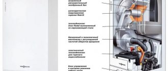
Many gas stoves are equipped with an electric ignition system. To control the flame of a gas stove, there is a special device - a thermocouple.
What it is?
Thanks to the thermocouple, the gas supply stops if the flame on the gas burner suddenly goes out. The thermocouple is installed not only on gas stoves, but also on other gas devices, such as boilers. This device is used not only for domestic purposes, but also in the energy industry, gas and oil production, and is also often used by pharmacists and biotechnicians.
The operating principle of this device is that it can measure the temperature of the device in which it is installed. The principle of operation is a sensor that determines whether the burner has gone out or is still working.
In order for it to function properly, it is necessary to carry out proper and timely care of the device.
Device
A universal thermocouple has several components.
- The base of the device consists of completely different types of metal, they are connected to each other by soldering. Metals can be of two types, often using pairs such as alloys of chromel and constantan, iron and constantan, aluminum and chromel, nichrome and nisil, as well as copper and constantan. It is worth noting that the simplest and cheapest metals used for a gas stove are aluminum and chrome.
- The device has a screen with digital symbols; if the temperature changes, it receives indicators in the form of numbers.
- The device has the power to open the magnetic valve at the moment when it is needed.
- The electric current coming from the device prevents the magnetic valve from closing. This makes it possible to stop the gas supply to the equipment if the flame goes out.
In addition, the thermocouple sensor is divided into two types.
- The sensor can be grounded. This is the most common type of device. It is produced by welding two metal ends, forming a common unit; at the end it has a special rod. This type of device responds very quickly. The fact is that the sleeve device is in direct contact with the outer shell. Despite most of the advantages, a device of this type has one disadvantage - the increased sensitivity of the device. If electrical interference occurs, the device immediately reacts to it.
- The thermocouple may also be ungrounded. In this case, the two metal ends are also welded, but they are not connected to each other. An example of such a device is a multimeter with a thermocouple. The advantage of this type of device is that it is not as sensitive as the first type, because it is equipped with a special cover - mineral insulation that separates the two elements of the device.
Let's move on to cleaning the column
Turn off the gas supply valve to the boiler. Using wrench No. 10, unscrew the fastening screw under the boiler door and remove the door.
Disconnect the wire connecting the piezoelectric element and the ignition electrode.
Using key No. 10, unscrew the thermocouple clamp. Using wrench No. 9, unscrew the thermocouple from the valve.
Note: it is necessary to ensure that the thermocouple does not rotate while unscrewing.
We note the depth of insertion of the nozzle into the main burner so as not to disturb the boiler settings.
Using wrench No. 17, unscrew the nut securing the copper tube from the burner to the valve. Using wrench No. 10, unscrew the ignition electrode from the pilot burner and the copper tube from the pilot burner and valve. Using a flat-head screwdriver, unscrew the two screws securing the pilot burner.
The gasket installed under the pilot burner has become unusable. It will need to be replaced.
Remove the nozzle from the pilot burner.
Tip: if the nozzle is stuck, you can lightly tap the burner with a key.
We unscrew the four screws securing the main burner to the boiler body and the screw securing the housing to be able to remove the main burner.
Lowering the main burner down, remove the copper tube from the valve.
Remove the main burner.
Remove the thermometer sleeve from the boiler body.
Using wrench No. 10, unscrew the four screws securing the top cover of the boiler and remove it and the insulation sheet under it.
Unscrew the two nuts securing the flue to the boiler body.
Remove the terminals from the draft sensor.
We remove the gas duct.
We remove the swirlers from the boiler heat exchanger. We clean them with a brush. If necessary, use a metal brush.
Clean the outer part of the heat exchanger with a metal brush. We clean the heat exchanger channels with a brush to the full depth. Clean the bottom of the heat exchanger with a brush. We also clean the gap between the boiler body and the floor. We clean the loose debris using a vacuum cleaner.
Using wrench No. 13, loosen the screw that fixes the depth of insertion of the nozzle into the main burner and remove it.
We clean the burner with a brush and a brush, and clean its holes with a vacuum cleaner. We clean the flue of dust from the outside and inside.
We clean the outer surface of the nozzle with a brush, then clean the nozzle holes with a needle or wire.
Note: The needle should be smaller in diameter than the nozzle hole. Even a slight increase in the diameter of the nozzle hole can affect the combustion mode.
We install the main burner in place.
We install a copper tube with a nozzle and attach its nut to the gas valve.
Only after this do we secure the nozzle to the burner at the mark using wrench No. 13.
Note: this sequence is necessary to avoid stripping the threads in the valve body.
Finally tighten the nut of the copper tube with wrench No. 17.
Clean the pilot burner with a metal brush.
This is how the thermocouple should be installed in the pilot burner (the tip of the thermocouple opposite the flame).
We install the pilot burner on a new gasket.
Before installing the nozzle into the pilot burner, it must be slightly rubbed against the tip of the copper tube for better sealing. The nozzle should also be cleaned or purged.
We connect the copper tube to the pilot burner and to the valve using a number 10 wrench.
The remaining parts of the boiler are assembled in the reverse order. When connecting, the ignition electrode should not be clamped with a key; it is enough to do it by hand, since it is made of ceramic and can easily crack.
We carry out control washing of all compounds. It will be possible to check the tightness of the connections of the copper tubes to the main and pilot burners only when the boiler is turned on.
Principle of operation
Many foreign-made gas stoves have a thermocouple component such as a gas control sensor. This device often acts up and cuts off the gas supply when it is completely inappropriate. For example, if a little water gets on the gas stove or there is a draft in the kitchen, the sensor will work and shut off the gas supply. The thermocouple in a gas stove is installed near the gas burners and in the oven.
First you need to determine what is the reason for the poor performance of the sensor. It may either not work at all, or work intermittently, or turn off the gas supply for no reason.
Often the cause can be outgoing contacts.
Sometimes the thermocouple just needs to be corrected or dirt removed. To clean the thermocouple, take a piece of sandpaper and rub it under the flame breaker structure several times.
There are two simple ways to check whether your sensor needs cleaning.
- Press the button and activate the electric ignition. If the burner is on, but as soon as you release the button it goes out, it means the contacts are not working. They need to be cleaned or corrected.
- After you lit the burner and released your hand, after a few seconds the flame went out - you need to check the contacts.
Water leaks
Inside the flow-through heater, water tubes are connected to various components using union nuts and rubber O-rings. Homeowners who have not maintained their units for years may find water dripping under the unit. If this is discovered, then repairing the gas water heater consists of checking all connections and replacing the seals.
There are other places where water can leak, for example, through the operating rod of the water unit. This suggests that, at a minimum, the seal on the frog rod needs to be replaced, which will require its removal and disassembly. In models equipped with a safety valve, the latter may also leak, especially if it has been released several times. Finally, the most unpleasant situation is a damaged heat exchanger in which a fistula has formed. Buying a new one is very expensive; it’s easier to repair the old one, which is discussed in the next section.
How to change a thermocouple?
Only a specialist should replace the device, as this is very dangerous. If the fastening is not airtight, then any breakdown of the device will give a spark, which will cause the gas stove to explode. To avoid a fire in your home, do not replace the thermocouple yourself, but ask a specialist to do it.
To replace the device, you will need to buy a new thermocouple from a specialized store. When choosing this device, choose only a high-quality device that will serve you for many years. Before buying a new device, consult with a specialist who will recommend exactly the sensor that is suitable for your gas stove or water heater.
Replacing a thermocouple sensor on a gas boiler is a little more complicated. In a gas boiler, a thermocouple made of chromium and aluminum or chromel and copel is most often used; an iron constant is less often used. All of these metals are designed to withstand high temperatures, and such sensors are often used in the foundry industry.
The gas boiler control system consists of an electromagnetic valve and a thermocouple.
To replace a device, you need to follow a series of sequential steps.
- Using a wrench, unscrew the nuts that secure the thermocouple to the solenoid valve, then you need to remove one of the ends of the thermocouple.
- Inspect the connectors. If they contain various contaminants or oxidation, they must be cleaned. For this you will need fine-grained sandpaper.
- Check the thermocouple sensor using a multimeter. To do this, attach one of the metal ends of the device to the multimeter, and heat the other with a lighter or torch. The multimeter reading should be within 50 mV.
- After that, if the indicator matches the data, you need to collect it in the same sequence. If not, then most likely it will have to be replaced.
If the thermocouple is in order, then the cause of the breakdown may lie in a malfunction of the solenoid valve. Clean the contacts that connect the two devices, then you need to check the operation of the sensor.
Replacing the thermocouple in the oven of a kitchen gas stove is carried out differently. First you need to remove the lid of the gas stove; it is located on the opposite side from where the oven tap handle is located.
Gas control repair manual
If the gas on the stove goes out, then the problem may lie not only in the thermocouple. However, most often this is precisely the problem.
The main sign of problems with gas control is that after igniting the burner and releasing the handle or button to open the “blue fuel”, the flame immediately goes out. This occurs due to the valve closing, since the thermo-EMF to keep it open is absent or insufficient.
The reasons for the noise of gas stove burners are described in detail in the article, the useful information of which is worth reading.
Before purchasing a new thermocouple, you need to determine the reason for the poor operation of the existing device - perhaps the problem is loose contacts on the valve, then you just need to tighten them
You should independently check, repair and replace the thermocouple in a gas stove with your own hands only when the gas is completely shut off. First you need to close the valve on the cylinder with the gas mixture or the methane pipe, and only then begin any work. Also, do not forget about turning off the power supply if the design contains volatile devices.
The thermocouple tip is located directly next to the burner and gas fire. And in the oven you can find it near the flame divider in the upper part of the oven. This tip should be free of carbon deposits, mineral deposits and any damage.
If the working tip of the thermocouple sensor is covered with scale, it must be cleaned off with sandpaper. The more carbon deposits, the less heat reaches the thermocouple, and the less it accordingly creates an EMF. The resulting millivolts may simply not be enough to open the solenoid valve.
How to check before replacing?
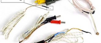
The thermocouple usually has one tip for installation near the fire. But there are also options with two or three temperature control tips. They are usually used in ovens, but it all depends on the specific model of the stove.
Thermocouples with several working tips have a peculiarity - if only one of them is not heated or fails, the solenoid valve will be closed. Therefore, in order to accurately find the cause of the problems, such thermocouple devices will have to be checked especially carefully. Only one of the sensors may be faulty.
A working thermocouple for a gas stove, when heated over a candle, produces an EMF of the order of 15–20 mV after 20–30 seconds - if less, then the sensor must be changed
Another point is that the thermocouple conductors in the area up to the valve must be tensioned or dangling in the body of the plate. At the same time, their connection to the electromagnet must be rigid; a connector hanging “on my word of honor” is unacceptable here.
The devices in question are produced with lengths from 40 to 130 cm. You should choose a thermocouple gas monitoring device based on this indicator very carefully. On the one hand, the conductor wire should not be over-tensioned, and on the other hand, it should not lie on heated surfaces or dangle freely.
How to change the device?
Before replacing a damaged thermocouple in a gas stove, you should inspect the device for:
- the presence of carbon deposits on the working tip (if there is any, it must be cleaned off with sandpaper);
- no burnout of this tip (in this case, only complete replacement);
- the rigidity of the connection between the contacts of the thermocouple sensor and the valve (if necessary, tighten);
- serviceability of the thermocouple itself with the output of an EMF at a level of at least 15 mV when heating.
The device in question should only be replaced when it is definitely faulty. In many cases, to get a gas stove to work again, you can get by by cleaning the tip from carbon deposits and checking the contacts.
To replace the thermocouple, you will have to remove the front panel from the gas stove, and also lift the top cover with the burners on it
The working tip of the thermocouple is rigidly fixed near the burner or burner using a nut. If it cannot be unscrewed due to scale, then you should not put too much pressure on the key. This can only break the fastening. It is better to use a solvent first.
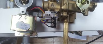
The second end of the thermocouple is attached to the solenoid valve using a threaded connector or two crimp contacts. Removing them doesn't seem difficult. The new thermocouple sensor is installed in a similar sequence - one end of it is attached near the burner, and the other to the electromagnet.
How can I check it?
Keeping your home safe is a working thermocouple sensor. Several times a year, the thermocouple requires mandatory checks and adjustments. To do this, invite a specialist who will perform a safe and accurate analysis of the device.
When checking thermocouple readings, consider the measurement quality of the device itself by systematically checking its operation.
Reasons for incorrect operation of the thermocouple:
- incorrect soldering of two metal rods;
- presence of electrical noise;
- you smell gas, there is a leak;
- thermoelectricity is inhomogeneous.
To resolve these issues, during device installation you should:
- choose a thermocouple with thick and large wire;
- avoid temperature changes;
- do not allow tension and vibration of the metal wire;
- use a sensor that has a working temperature spread.
You need to check the serviceability of the thermocouple by following the step-by-step instructions.
- The thermocouple has two ends. When checking, one of them must be heated with a flame from the igniter, and the second must be secured to the thread of the valve (electromagnetic) using a nut.
- The next step is to separate it from the boiler. Then you need to ensure a stable flame. A gas burner is also used for this purpose. But experts advise using a candle flame.
- The tip of the device is immersed in the flame, it should be approximately 1 cm above the flame. Here you need to remember that the fire heats the device to almost half, so it is better to hold it by the tip.
- Next, a tester is used that determines millivolts. It is connected to the output contact and to the body of the thermocouple itself.
- If the thermocouple is working properly, then 30 seconds after heating the result will be from 17 to 25 mV. But if this indicator does not exceed the minimum threshold, then this means that it is faulty.
You can find out more about how to replace a thermocouple on a gas stove.
The thermocouple for a gas boiler is a thermoelectric converter for automatic control and monitoring systems of gas equipment. The device serves as the main element of gas control protection and is designed to ensure the fastest possible shutdown of the gas supply in the event the flame goes out.
Comments
I especially liked “try to revive your gas control or “kill” it completely by turning the stove into a USSR device that works just fine without gas control”
- Login to reply
Either no one is reading this, or one of two things. Interesting article. It's a pity, it's hard to read... The font is small and blurry. And in the pictures the text (in the explanatory frames) is completely unreadable. Apparently the material was ripped off from somewhere and copied poorly. I'd like to see the original.
- Login to reply
reset your @ . I'll send it to you by email. article. if there is the same effect, I will correct it, I am the “aftar” of this creation. I don't do plagiarism. ). poked around personally..
- Login to reply
It is not clear why the quality was lost. The original Word document looks flawless.
- Login to reply
- Login to reply
Good afternoon. I wanted to get an opinion or get advice from experts. The valve “stopped” working: I checked the thermocouple separately - it produces 40 mV from a regular burner; I checked the valve - it works exactly starting from 700 mV (dead AAA battery). I don’t understand what the problem is yet, because... It seems like the emf of the thermocouple is within normal limits (I’m very surprised by the reading of your thermocouple. Maybe there’s a problem there.). Because the valve operates from external power, I wanted to know whether the winding on the valve will not be covered when used in this way?
- Login to reply
Good afternoon, I don’t know the indicators of the thermocouple, because... it failed, but the valve was triggered somewhere around 1V, “pulled” 400mA. My entire “kitchen” in the post, when powered by an external power supply, is relevant as a temporary solution to the problem during the period of purchasing (purchasing) a valve or thermocouple, or a kit in general. If you don’t think about buying them, unscrew the valve, remove the rubber gasket, remove the spring - the headache will disappear. ) The stove will turn into the USSR - a device. )Good luck.
- Login to reply
PS. Try repairing the contact connections by removing the thermocouple, cleaning the seat, etc. connections between the terminal and the housing. It seems to me that your thermocouple is bad. Don’t worry about the valve winding. Increase the voltage until the valve operates - it will not take extra current.
- Login to reply
Thank you for such a quick response! I have already cleaned the thermocouple contacts as much as possible, but, alas, or fortunately, there was nothing to clean there except carbon deposits. I have already taken measurements on a test bench without unnecessary details. Considering the gluttony of the valve, it also seems to me that the problem is in the thermocouple, but in contrast to this there is a table of TEDS of standard thermocouples (https://kipiya.ru/2008/04/04/tablica-termo-eds-standartnyx-termopar/, https:/ /temperatures.ru/pages/graduirovochnye_tablicy), where the maximum readings do not exceed 70 mV. That is why I began to look for help, because at the moment I have two impressions: the valve winding has deteriorated since it requires so much to hold and the thermocouple has deteriorated since it produces so little. But neither of these stand up to criticism. Or am I missing something. In general, there are two options left: either remove the valve or buy a kit. For now, I’ll just bypass the thermocouple using external power.
- Login to reply
in terms of standards - the table focuses on industrial thermocouples, low-current (USSR-CIS standards), as for gas control - these thermocouples are “tailored” for bourgeois stoves. In fact, industrial thermocouples produce a LOW-CURRENT SIGNAL to electronic devices (with further amplification thereof) for control thermal processes. As for the t/p gas control, it (it was specially developed for the valve) produces a significant current to the valve, and the valve needs to overcome the resistance of the spring and also press down the gasket. In production there are hardening transformers (soldering of cutters). They produce 2 volts from the step-down winding between the contacts. The cutter is clamped and heated. The current is 400 - 600A. Approximately the gas control thermocouple is rated for a current of up to 500mA. Gas control cuts off the gas from the oven faucets, burners... It won’t go anywhere else until you open the faucet. If you look at the comments on the Internet about gas control, you can conclude that it is not perfect and is short-lived. = flush cistern with electronics unit. ) They install it to “make money” (IMHO). and there are no spare parts. There is a place for do-it-yourselfers to practice.
The design and principle of operation of a thermocouple in a gas boiler
The thermocouple consists of two conductors made of different types of metal, resistant to maximum temperatures, which are connected in a ring. One of the soldering points is installed in the measurement area, the second is connected to the converter device. The physical phenomenon in the form of the thermoelectric effect (Seebeck effect) forms the basis of the operating principle of the thermocouple:
- two elements from different metal bases are firmly connected at one point. The difference in the composition of the conductors is a fundamental factor in the operation of the device;
- when the junction is placed in an open fire, a potential difference appears at the other ends of the soldered conductor.
What does a thermocouple look like for a gas boiler?
Next, a voltmeter is connected to the cold ends of the device, the circuit is closed and the measuring device shows the voltage.
High Temperature Measurement
If you measure in the medium (400-1500 °C) or high (1600-2500 °C) temperature range, then in this case protection is used in the form of a cover made of fire-resistant materials. High density and heat resistance are the requirements that apply to protection.
Advantages:
- — reliability;
- — no self-heating;
- - cheapness;
- - high accuracy;
- - wide temperature range.
Flaws:
- -complexity of signal processing;
- — susceptibility to corrosion;
- — susceptibility to interference;
- — low sensitivity (about 0.1 mV/°K);
- - high initial resistance;
- - need for support.
How does a flame sensor work in a gas boiler?
A flame ionization sensor is a device that is designed to ensure the safe operation of gas boiler equipment. The device monitors the presence of fire, and if it detects a lack of flame, it automatically turns off the boiler. The operating principle of the gas boiler flame sensor provides the following:
- the functionality is based on the formation of ions and electrons when the flame is ignited. The formation of an ionic current causes the process of attracting ions to the ionization electrode. The device is connected to a combustion control sensor;
- If, when checking with a combustion control sensor, the formation of a sufficient level of ions is detected, this means that the boiler is operating normally. If the ion level decreases, the sensor blocks the operation of the boiler equipment.
The key reasons for the operation of the ionization sensor include contamination of the valve and incorrect gas-air level ratio. This also happens when a large amount of dust settles on the ignition device.
Main types of thermocouples for a gas boiler
In the manufacture of thermoelectric converters, alloys of noble and base metals are used. For specific operating temperature ranges, certain groups of alloys are used. Depending on the metal pairs used in manufacturing, devices are divided into several types. The following types of devices are most often used to operate boiler equipment using gas fuel:
- thermocouple type E. Factory marking ТХКн, consists of plates made of chromel and constantan. The device is designed for a temperature range from 0°C to +600°C;
- type J. Provides a composition of iron and constantan, TFA marking. Used for operating temperatures ranging from -100°C to +1200°C;
- type K with TXA marking, made on the basis of plates of chromel and alumel. The temperature range of application of the K-type thermocouple is significant – from -200°C to +1350°C;
- type L with THC marking. The structural elements are chromel and copel. The device is designed for temperatures from -200°C to +850°C.
Thermocouple for gas boiler type J
The following product samples are used in heavy industry:
- type S with TPP10 marking is a platinum-rhodium-platinum composition. Used in installations at temperatures up to +1700°C;
- type B with TPR marking consists of a composition of platinum-rhodium-platinum-rhodium plates. The product is intended for the temperature range from -100°C to +1800°C.
Other versions of similar devices are also manufactured from precious metal alloys, which are relevant in heavy industry and foundries.
Types of temperature sensors for gas
Thermocouples of gas stoves differ in the alloy of conductors and the type of connection to the valve. And the main thing here is that each manufacturer of gas-powered equipment uses its own versions of electromagnets with different connection connectors.
We recommend: Commissioning of a heating system: how to set up a heating system in an honest home, pressure testing and adjustment
In most cases, it is impossible to move the thermocouple gas control sensor from one tile to another.
The thermocouple must correspond to the model of the gas stove; installing a “left” control device is prohibited for safety reasons
The following alloys and metals are used to create thermocouples:
- constantan + chromel;
- copper + constantan;
- copper+copel;
- nisil + nichrosil;
- alumel+chromel;
- constantan+iron;
- chromel+copel;
- platinum+platinum;
- tungsten+rhenium.
The accuracy of the device and its operating temperature range depend on the alloys used. For example, a chromel-alumel thermocouple is designed to operate at 0–1100 0C, an iron-constant thermocouple at 0–700 0C, and a platinum-platinum-rhodium thermocouple can withstand heating up to +1700 0C.
Household gas stoves usually use thermocouple sensors made of alumel and chromel or constantan and iron. They are inexpensive and quite suitable for the temperature conditions of a gas cooktop.
Thermocouple in a gas control system
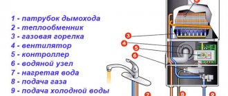
When operating gas equipment, non-volatile automation is required, which helps to quickly shut off the gas supply in case the flame suddenly goes out. Modern heating boilers with a gas burner are equipped with a gas control system, which includes an electromagnetic valve and a thermocouple. The components of the electrovalve include:
- core with winding;
- cap;
- return spring;
- anchor;
- rubber band blocking the gas supply.
When you press the gas supply button, the rod is buried inside the coil and the spring is charged. According to the regulations, the supply valve should be held for about 30 seconds so that the thermocouple warms up and voltage is generated at the ends to hold the valve inside the coil. The thermocouple begins to cool if the burner goes out. What happens next:
- this is accompanied by a decrease in voltage at the ends of the thermocouple;
- the return force of the spring exceeds the electromagnetic force that holds the rod inside the coil;
- the valve returns to its original position and the gas supply is shut off.
This is the job of a thermocouple in a gas boiler. The gas control system based on a thermocouple is highly reliable, including due to the fact that it can function without being connected to the power grid.
Connection nuances and verification
Connect the thermoelectric converter to the measuring device using a compensation cable. In order to minimize the measurement error as much as possible, the cores of this wire are made of the same material as the sensor itself.
Check the functionality of the thermocouple as follows:
- one end of the device is connected to a multimeter;
- the other end is manually heated using a lighter or gas torch.
To check the functionality of the thermocouple, connect one end of the device to a multimeter
If the device is in good condition, this is indicated by the presence of a voltage in the region of 50 mV.
Possible malfunctions and methods for eliminating them
If, when you press the gas supply button, the burner turns on and immediately goes out, this indicates a malfunction of the thermocouple. It may also be the result of poor contact between the converter and the solenoid valve.
Repairing a gas boiler thermocouple malfunction is as follows:
- remove the end of the thermocouple by unscrewing the clamping nut with a wrench, with which the transducer is attached to the valve;
- if upon inspection the presence of contaminants or oxides is detected, clean the contact area with fine sandpaper;
- Next, use a multimeter to check the functionality of the device.
If the valve is in working condition, it is necessary to ensure the correct connection of the converter to the valve: find the appropriate position of the clamping nut for optimal contact.
You should know that if the gas boiler converter fails, the device cannot be restored. Here it is necessary to replace the thermocouple by installing a new sample in its place. Products in this category are offered by many domestic and foreign manufacturers, including Arbat, Zhukovsky AOGV plant, Honeywell concern and other industrial companies. The price range for this device varies between 600-2000 rubles.
The main areas of application of thermocouples are automation of gas equipment, foundry industry installations and many other areas of production. Based on this device, a whole range of thermostats and thermometers for household and industrial use has been developed. In the hands of folk craftsmen, a thermoelectric converter can become the basis for a mini power station; it is used to create chargers with which you can charge low-power devices from an open fire, including from a fire.
From this article you will learn what problems can arise in the automation of gas boilers, why it is impossible to ignite the igniter, which is why the boiler can turn off for no reason, and most importantly, we will figure out what actions need to be taken to diagnose and eliminate this malfunction.
Owners of non-volatile gas boilers are probably familiar with the situation when, for some reason, it is not possible to ignite the boiler, or a lot of time is spent on ignition. In this case, the problem lies in the boiler automation.
Today, the gas valve EUROSIT 630 is most often used in domestic and imported gas equipment. It is this valve that performs the function of maintaining the set coolant temperature and, in the event of an emergency, completely shuts off the gas supply to the burners. Further starting of boilers with such automation is only possible manually. However, the cause of a boiler emergency shutdown is not always a real accident.
Let's try to understand this using the example of the Zhitomir-3 boiler. Automatically, it provides protection against loss of flame on the igniter and loss of traction.
Note: All gas-hazardous work must be carried out exclusively by representatives of specialized organizations that have the appropriate permits. Therefore, this article is provided for informational purposes only. This article will also help you monitor the work of the technician and, perhaps, save you from the need to purchase unnecessary spare parts.
Let's decide what we will call igniting the igniter. The EUROSIT 630 valve control knob allows you to switch the boiler to three main modes:
- disabled;
- ignition;
- temperature adjustment (1–7).
To ignite the pilot burner (igniter), you must move the control knob to the “ignition” (spark) position, press it and use the piezo ignition button to ignite the pilot burner. Next, the handle is held for several seconds (no more than 30) and released. The pilot light should continue to burn. This is what we will call igniting the igniter. If the pilot light goes out, you need to repeat the procedure several more times. If this does not help, you need to look for the problem.
At the moment the igniter is ignited, the flame heats the thermocouple, which in turn generates an EMF (approximately 25 mV for working SIT thermocouples), which is supplied through the automation sensor(s) circuit to the solenoid valve.
Problems with ignition
There are two types of ignition systems for atmospheric heaters; we will analyze them separately:
- manual, with a spark from a piezoelectric element;
- automatic, battery powered.
For reference. The most modern models of dispensers are ignited automatically from the energy generated by a hydrogenerator. Everything here is relatively simple: if the ignition does not work, then the reason for this is low pressure in the water supply, or the generator itself has failed.
With the manual ignition method, sometimes a malfunction of the gas water heater is observed, such as failure of the thermocouple. Then, when the regulator or button is released during ignition, the wick that was just burning goes out again. The fact is that the temperature-sensitive element must heat up from the igniter while you hold the handle and apply current to the solenoid valve. The latter will hold the mechanism for you when you release it. If this does not happen, then the contact in the circuit is broken or the thermocouple must be replaced. To perform this operation, it is better to invite a specialist.
As for automatic ignition systems, malfunctions of geysers during the ignition process are not limited to low batteries, as is written on many Internet resources. In addition, any more or less modern model of heater, even Russian-made, is equipped with an electronic low battery indicator. So the user knows when it is time to change them.
The device will not even begin the process of igniting the igniter until the hot water tap opens and the required pressure appears in the network. When there is not enough of it, the column will not show any signs of life. The same thing will happen if there is insufficient gas pressure or after a shutdown as a result of the draft sensor being triggered (until it cools down). It is better for a specialist from the relevant service to deal with poor gas pressure; you will not be able to do this yourself.
Since we are considering internal malfunctions of the column, we can name a clogged mesh at the entrance to the water unit as the culprit of low water pressure. If the charge of the batteries is normal, the water and gas pressure is sufficient, and the heater makes clicks of a spark discharge, but the matter does not go further, then move on to the next section.

