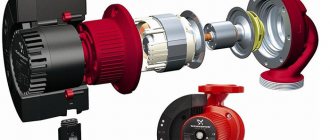
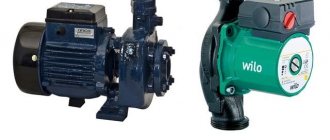
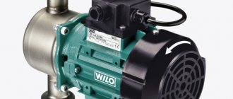
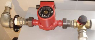
Uniform distribution of the coolant inside the pipeline and radiators is ensured by using a pump for the heating boiler. The device maintains the required pressure in the system, helping the fluid overcome a difficult path. You can install the circulation pump yourself if you read the instructions and technical design of the device.
Circulation pump in a gas boiler
The circulation pump in the design of a gas boiler accelerates the coolant through the heating system, due to which the coolant cools in the system more slowly and returns to the boiler in a “heated” form. Since heating in the boiler occurs to a certain temperature, the next heating cycle of the coolant will be shorter. This results in lower gas consumption and faster water heating cycles (higher efficiency).
It is believed that hydraulic heating systems do not require the installation of circulation pumps, however, it will not interfere at all in old heating systems with large diameter pipes.
By purchasing a gas boiler with a circulation pump in the design, you no longer need to install a separate circulation pump in the heating system.
conclusions
- The circulation pump in the design of a gas boiler improves the operation of heating systems, both single-circuit and double-circuit heating boilers.
- The circulation pump is especially relevant in the design of a wall-mounted boiler.
©Obotoplenii.ru
Other articles in the section: Gas boiler
- Advantages of a condensing heating boiler
- Types of gas boiler burners
- Circulation pump in the design of a gas boiler
- Installation of a wall-mounted gas boiler: canopy of a gas boiler and preparation for connection
- Various pipes for piping a wall-mounted gas boiler
- Installation of a gas boiler: preparatory work for installing a gas heating boiler on the wall
- How to flush the heat exchanger of a gas boiler
Types of pumps
To ensure that the energy carrier circulates efficiently, dry and wet pumps are used.
Dry
In equipment of the first type, contact of the rotor with the coolant is not provided. The seal used in such a device hermetically separates the pump itself from the motor. The efficiency of this equipment is 80%, so it is advisable to use it when constantly pumping large amounts of liquid.
The area of application of dry pumps is shopping centers, factories, factories. In private homes, such structures are not used due to the high level of noise generation.
Wet
The rotor of wet pumps is located in the coolant, which they pump. Water cools the engine. The stator included in the design serves to supply electricity. Pumps with a “wet” rotor have a lot of advantages: long service life, rare maintenance, low noise generation, small size, ease of replacing blocks.
Disadvantages - low efficiency (about 30-50%), limited scope of application (private houses and city apartments), inability to use pumps for drinking water and for anything related to food.
Network pump design and principle of operation
SE type pumps have a horizontal design. These are units that operate thanks to centrifugal force. For this purpose, an impeller with two-way motion is installed in a spiral casing with a horizontal split. The rotor rests on external-type rolling bearings with forced or ring lubrication. The drawing of the network pump forces you to pay attention to the mechanical seals of the shaft seal. They are supplied with a locking and cooling fluid; this “jacket” is mandatory for units of any power.
The working shaft of the network unit is located horizontally, this is typical for all SE models. The casing connector is also located in a horizontal plane, which provides easy access to pump parts and their quick replacement in the event of an accident or scheduled repair. These pumps are available in single-stage and multi-stage types.
The slot seals of the units are made of corrosive alloys; chromium steel is used for the impeller. The body and covers are cast from gray cast iron, which allows the equipment to be used in the climatic conditions of the Far North.
Structure of the network pump symbol
SEN 1250-140 UHL3
Where,
- C – network;
- E – electric;
- N – pump;
- 1250 – nominal flow, m3>;
- 140 – nominal pressure, m;
- UHL3 – climatic version.
How to install an additional pump in a heating system - theory and practice
Content:
Arranging and operating the heating system of a private home can sometimes be problematic. So, the following problem often arises - the coolant moves unevenly through the pipeline, which is why heating the house is not effective enough.
An additional circulation pump built into the heating system will help solve the problem. Such a device can be connected to structures operating on any type of fuel. This article will discuss how to install an additional pump in the heating system.
Advantages of circulation pumps
An additional pump in the home heating system allows for a number of advantages, including:
- Significant increase in heating efficiency;
- Increasing the rate of heating of rooms and increasing the heated area;
- The temperature regime in the heating circuit becomes more uniform;
- The pipes do not become airy;
- Energy consumption for heating is reduced;
- It becomes possible to connect various dryers and thermostats to the system;
- The size of the pipes used for heating can be reduced.
In addition to the qualities described above, circulation pumps can boast a relatively low cost, so their installation will not require any special expenses. An additional pump in the heating system will increase heating efficiency without making significant changes to the design of the system.
Pump characteristics
All circulation pumps have two main parameters:
- N – pressure value, i.e. the height to which the pump can lift liquid (measured in meters);
- Q is the fluid consumption over a certain time period (measured in cubic meters), which is directly dependent on the power of the heating boiler and the diameter of the pipes used.
Schemes for different types of systems
Initially, it is necessary to determine the insertion area of the circulation device. With its help, the process of active movement of liquid is carried out - the flow passes through the boiler and is forcibly directed to the heating radiators.
To locate a household pump, it is necessary to determine the most convenient area so that it can be easily serviced. On the supply side, it is installed after the safety block and shut-off valves of the boiler.
On the return pipeline, the pump is placed after the expansion tank in front of the heat generator.
Due to the presence of various mechanical impurities in the water, for example, sand, problems may arise in the operation of the pumping mechanism. Particles contribute to jamming of the impeller, and in the worst case, stopping the motor. Therefore, you will need to install a strainer strainer directly in front of the unit.
Separately, it is worth mentioning the issue of an open-type heating system. It is capable of operating in two modes - with forced and gravity coolant circulation.
The second option is more suitable for areas with frequent power outages. This is much more economical than purchasing an uninterruptible power supply or generator. In this case, the unit with shut-off valves must be installed on the bypass, and a tap must be inserted into the direct line.
In stores you can find ready-made units with a bypass. In place of the flow tap, there is a spring-loaded non-return valve. This solution is not recommended - the valve produces a resistance force of 0.1 Bar, which is considered a large indicator for a gravity-type circulation system.
It is better to use a reed valve instead. However, its installation is carried out strictly horizontally.
Step-by-step instructions for assembling and installing the pump
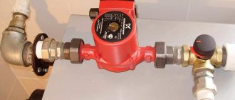
After purchasing the device and choosing the location for its installation, it is necessary to carry out assembly and installation. It is first necessary to install ball valves on both sides of the pump, and install a mud trap in front of the unit to retain scale, dirt, and abrasive particles. The upper part of the bypass must be equipped with an air valve.
Assembling and connecting the pump to the heating boiler is carried out in the following sequence:
- Before installation, drain the liquid from the system. For complete cleaning, you need to fill it with coolant and drain it, then repeat this procedure a couple more times.
- Install the pump into the system.
- After installation, all connections must be carefully sealed.
- Fill the system with liquid. Remove excess air.
- Connect the device to the electrical network.
The number of circulation devices required in the system depends on the length of the pipeline.
Where to install
There are different opinions among experts regarding the installation of the unit in the system. Some suggest installing the pump on the supply pipeline, others on the return line.
In a home system, the temperature rarely rises above 70 °C, and the liquid does not heat up more than 90 °C. Therefore, the unit can be embedded in both the supply and return pipelines, while the difference in statistical fluid pressures between them is not significant, but it is better to focus on the second option. If there are two separate branches in the heating system, then it makes sense to install a separate device on each.
The pump must be installed immediately after the boiler, before the first branch in the circuit. Then it will be possible to set the required thermal conditions in each part of the house.
Forced circulation
In houses with a large area, air pockets may form in the system, which leads to disruption of circulation, overheating of the coolant in the boiler and damage. Therefore, a pump is installed in the return pipe before entering the boiler heat exchanger, which carries out forced circulation. This allows you to maintain the desired fluid speed and pressure.
The coolant often contains mechanical impurities that can damage the engine or cause the impeller to jam, so a dirt filter is installed in front of the device. Ball valves installed on both sides of the device allow you to repair or replace the unit without draining the liquid from the system.
Natural circulation
The process got its name based on the laws of physics. Thanks to the strictly maintained slope of the supply and return pipes, the heated liquid rises to the top point of the system, then, as it cools, it falls down, returning to the boiler. When operating in this mode, heat transfer will be low, in addition, a power outage is possible, so a pump is installed into the system. This gives high heating efficiency and reliability.
Additionally, a bypass line for the pump is installed - a jumper, which makes the system operational when the boiler is turned off. A ball shut-off valve is installed in the jumper. It opens when the power goes out or the appliance fails. The tap leading to the pump is closed, and the system begins to operate on the principle of gravity.
Where circulation units should not be installed
It is not advisable to install circulation pumps on the supply line. There are cases when air accumulates in the upper part of the boiler, the device cannot draw it in, as a result, a vacuum is formed, which leads to boiling of the coolant.
The resulting steam-water mixture begins to move into the system. The pump stops because it can only pump water. If measures are not taken in time, an explosion is possible.
Hydraulic separator
If there is a need to install an additional pump, then another device must be included in such a heating system - a hydraulic separator. In the list of terms used, a hydraulic separator can also be called an anuloid or a hydraulic arrow.
Operating principle of hydraulic separator
Such devices are recommended for use in heating systems where the coolant is heated using long-burning boilers. The fact is that the heating devices in question can operate in several phases (fuel ignition, combustion process and attenuation), and for each of these phases it is necessary to maintain a certain combustion mode.
Installing a hydraulic needle in the heating system allows you to create a certain balance in the operation of heat and warming up the system. The anuloid itself is made in the form of a pipe with four outlet pipes. The main functions of such a device include:
- Automatic removal of accumulated air;
- Collecting sludge particles (works as a dirt trap).
Note! From these characteristics it can be understood that the hydraulic separator is considered an important device in the heating system, so it must be installed without fail if there is a pump.
Hydraulic separator in the heating system
Heating in a private house performs many functions that must be implemented regardless of coolant flow and possible pressure drops in the pipelines. It is quite difficult to achieve efficient operation of the system, because the liquid enters the pipeline circuits from one source of thermal energy - the boiler, which will ultimately lead to unbalanced heating. To prevent such situations, the hydraulic separator serves; it performs the function of decoupling.
Scope and characteristics
Characteristic features of network pumping devices are ease of installation and low maintenance. Materials such as high-quality steel and gray cast iron, from which such equipment is made, help to increase the safety margin and durability of the pump. The technical characteristics of network pumps allow them to work with predominantly clean water, which should not contain solid parts with a diameter greater than 0.2 mm, as well as more than 5 mg/l of mechanical impurities.
Most often, network pumping devices are used to create water circulation in heating networks, as well as to service a boiler (heating) network installation. Such units are manufactured both with one gear and in a 2-stage version. The drive operates using electric power units (motors). They look like horizontal pumps.
The units also include in their device:
- housing with horizontal connector;
- impeller with double-sided water inlet;
- bearings, shaft and end sealing elements;
- chambers for end seals and flanges for mounting bearings installed in the housing;
- rolling bearings that support the rotor;
- roller or ball support bearing for drive;
- bearing for the radial axis.
In boiler houses, several identical pumps are installed in parallel.
The average water supply of devices for boiler houses is 450-500 cubic meters per hour, the pressure is in the region of 50-70 m, and such a parameter as inlet pressure varies within 16 kilograms per square centimeter. Pumps whose purpose is to circulate hot water in small heating systems have lower power and performance indicators, but they also cost an order of magnitude cheaper.
The scope of application of network products is not limited only to heating systems, in particular boiler rooms. This equipment is successfully used for supplying fuels and lubricants to bases, warehouses and industrial enterprises, for pumping reagents into water treatment plants, as well as in water treatment systems designed for pumping water into water supply systems when the pressure level in pipes drops. At the same time, such equipment is also used for cleaning tanks contaminated with sludge, as well as storage facilities for substances such as fuel oil.
Technical characteristics of the product “Network pumps”
| Capacity (feed) | 500…5000) m³/hour |
| Pressure | 55…180 m |
| Efficiency no less | 87 % |
| Designated service life is not less than | 20 years |
| Motor speed | 1500, 3000 rpm |
| Electric motor power, no more | 3150 kW |
Dimensions and weight
The lineup
| Name | Productivity, m3/hour | Head, m | Temperature of the pumped medium, C° | Seal type: M-lip, T-face, DT-double face | Nutrition | Engine power, kW | Rotation speed, rpm |
| Network pumps | 55…180 | 3150 | 1500, 3000 |
Temperature of the pumped medium of UODN pumping units, °C: -20…+90
Main Applications
In municipal services and industry, a network water pump has the following applications:
- is part of high-power boiler installations;
- for water recirculation for boilers;
- as part of waste heat boilers;
- supply and pumping of coolant in heating networks;
- water supply to technological lines of large enterprises.
Installation diagram
In practice, two schemes for installing a circulation pump are used in a single-pipe and two-pipe heating system. Before carrying out installation work, you must carefully study the attached instructions. At the preparatory stage of work, water is drained from the system and the pipes are cleaned of contamination by additional pumping of liquid. The pump is installed according to the attached diagram, then coolant is poured into the circuit and the unit is turned on.
As we have already said, it is best to install the pump on the return side using a tap or, as it is also called, a bypass. Such a device is necessary to shut off the water and replace the pump in case of breakdown. The diameter of the outlet pipe should be smaller than that of the central pipeline.
Installation diagram of an additional pump in the heating system
At each edge of the bypass, before entering and after exiting the pump, taps are installed for emergency shut-off of the coolant. Another valve is installed on the central line to direct the flow of liquid through the pump. Before entering the pumping equipment, a special filter is attached that will accumulate harmful particles in the water.
Network pumps type SE
| Pump unit size | Pump parameters | Motor parameters | Dimensions of the pump unit, mm | Ma, kg | |||||
| Q, m3/h | H, m | Type | Nd kW | n, min-1 | L | B | H | ||
| SE 500-70-16 | 500 | 70 | 5AN280A2 | 160 | 2950 | 2300 | 1050 | 1065 | 2328 |
| SE 800-55-11 | 800 | 55 | 5AN315A4 | 200 | 1450 | 2485 | 1155 | 1102 | 2710 |
| SE 800-100-8 | 800 | 100 | 5AN355A2 | 315 | 2950 | 3720 | 1695 | 1500 | 4840 |
| SE 800-100-11 | 800 | 100 | 5AN355A4 | 315 | 1450 | 3995 | 1370 | 1840 | 5250 |
| SE 1250-70-11 | 1250 | 70 | 5AN355A4 | 315 | 1450 | 3080 | 1236 | 1235 | 4200 |
| SE 1250-140-8 | 1250 | 140 | n/a | 800 | 2950 | 4073 | 1695 | 1515 | 5860 |
| SE 1250-140-11 | 1250 | 140 | A4-400U4 | 630 | 1450 | 4375 | 1530 | 2220 | 7365 |
| SE 2500-60-8 | 2500 | 60 | A4-400U4 | 630 | 1450 | 3995 | 2345 | 2070 | 7980 |
| SE 2500-60-11-1 | 2500 | 60 | A4-400U4 | 630 | 1450 | 3995 | 2305 | 2070 | 7210 |
| SE 2500-180-8 | 2500 | 180 | 4АЗМ1600/6000 | 1600 | 2950 | 4770 | 1975 | 1710 | 8580 |
| SE 2500-180-10 | 2500 | 180 | 4АЗМ1600/6000 | 1600 | 2950 | 4410 | 1770 | 1610 | 6800 |
| SE 5000-70-5 | 5000 | 70 | 4АЗМ1250/6000 | 1250 | 2950 | 4365 | 1940 | 1720 | 10400 |
| SE 5000-160-8 | 5000 | 160 | 4АЗМ3150/6000 | 3150 | 2950 | 5450 | 1900 | 1590 | 13900 |
| SE 5000-160-10 | 5000 | 160 | 4АЗМ3150/6000 | 3150 | 2950 | 5450 | 2175 | 2210 | 13200 |
Design of SE type pumps
- centrifugal, network pumps of the spiral type, with double-entry wheels;
- the pumps are made with a horizontal housing split.
Design of SE type pumps
- The main design is horizontal, single-stage pumps;
- Pumps types SE800-100-11, SE1250-140-11 - horizontal, two-stage;
- The pumps are equipped with a water jacket for cooling the seal units.
SE type pumps are used to power heating networks of fuel and energy complex enterprises. The pumped medium is industrial water.
Characteristics of the pumped medium
- The content of solid inclusions is no more than 5 mg/l.
- Particle size is no more than 0.2 mm.
- The temperature of the pumped medium is up to 453K (up to +180°C).
Pump shaft seal
- stuffing box seal - at a temperature of the pumped medium up to 373K (up to +100°C);
- mechanical seal - at a temperature of the pumped medium up to 453K (up to +180°C).
Material of the wet part of SE type pumps
- Body - modified cast iron;
- impeller - steel 20X1ZL.
Limitations on the use of pumps and pumping units of the SE type
- backwater in front of the impeller entrance - no more than 100 m w.c.;
- permissible vacuum suction height - from 3.0 m to 5.5 m.
With warm floor
Note! In the “Warm Floor” system, the circulation pump is installed in a horizontal position after the mixing unit in the supply pipeline section. In some wiring schemes, several such devices are installed, each of which will pump liquid within one floor.
Installation diagram of the pump in the “Warm Floor” system
How to choose a pump: calculation
To select a unit, take into account the performance, pumping medium and calculate the required pressure. It shows the difference in the medium difference when the unit is turned off and on, measured in m.v.s., it is calculated using the formula:
H=(L xR xZ)/(ρ xg),
L – total length of the pipeline in two directions, m. R – losses in pipes per 1 m are 150 Pa; ρ – specific water density 1000.0 kg/m3; g – 9.80 m/s2. Z – correction factor.
Calculation: 2000Х150Х1.3/1000Х9.8 = 39.79 m or 4 atm.
Cost of different types of pumps
There are many companies on the market specializing in the production of circulation units. Consumers are advised to buy models from reputable European manufacturers. The products of some Russian enterprises are also in demand.
| Model | Manufacturer country | price, rub. |
| Prima UPS 25/60 180 | Russia | 1570 |
| Wester WCP 25-40G | Russia | 2127 |
| LRP 32-50/180 | China | 2598 |
| Hoffmann UPC 25-40 180 | Germany | 5256 |
| Yonos PICO 15/1-4 | Germany | 6051 |
| A 56/180 XM | Italy | 10953 |
You can find both budget and expensive models on sale. Which pump to buy for a heating boiler is an individual decision for the home owner. When choosing, some are guided by the level of popularity of the manufacturer, others - by cost, and still others - by the availability of the service. Learn how to choose a heating radiator by following the link.
Rules for connecting to power supply
The circulation pump is powered. The connection is standard. It is recommended to install a separate power supply line with a surge protector.
To connect, you need to prepare 3 wires - phase, neutral and ground.
You can choose any of the connection methods:
- through a differential machine device;
- connection to the network together with an uninterruptible power supply;
- power supply to the pump from the boiler automation system;
- with thermostat regulation.
Many people wonder why complicate things, because connecting the pump can be done by connecting a plug to a wire. This is how the pumping device is plugged into a regular outlet.
However, experts do not recommend using this method due to the risk of unforeseen situations: there is no grounding and a safety device.
The first option is not difficult to assemble yourself. It is necessary to install an 8 A differential circuit breaker. The wire cross-section is selected based on the device rating.
In the standard scheme, the power supply is carried out to the upper sockets - they are marked with odd numbers, the load - to the lower ones (even numbers). Both phase and neutral will be connected to the machine, so the connectors for the latter are designated by the letter N.
To automate the process of stopping the circulation of the coolant when cooling to a certain temperature, an electrical circuit is used to connect the pump and thermostat. The second is mounted in the supply line.
At the moment when the water temperature drops to the specified value, the device disconnects the electrical supply circuit.
There are no difficulties in supplying electricity through an uninterruptible power supply; it has special connectors for this. A heat generator is also connected to them when there is a need to provide electricity.
If you choose the method of connecting the pump to the boiler control panel or automation, you will need good knowledge of the power supply system or the help of a professional.
The feasibility of using automatic and manual switching between two boilers
Let's consider the following five options with various units in conjunction with an electric boiler, which is in reserve and must turn on at the right time:
- Gas + Electric
- Firewood + Electric
- Liquefied gas + Electro
- Solar + Electro
- Pellet (granular) + Electro
Pellet and electric boiler
The combination of connecting two boilers - a pellet and an electric boiler - is best suited for automatic switching on and manual switching is also allowed.
A pellet boiler may stop because it has run out of fuel pellets. It got dirty and wasn't cleaned. The electric one must be ready to turn on to replace the stopped boiler. This is only possible with automatic connection. Manual connection in this option is only suitable when you permanently live in a house where such a heating system is installed.
Diesel boilers fuel and electricity
If you live in a house with such a system for connecting two heating boilers, a manual connection is quite suitable for you. The electric boiler will operate as an emergency boiler in case the boilers fail for some reason. They didn’t just stop, they broke down and require repairs. Automatic switching is also possible as a function of time. An electric boiler can operate in tandem with liquefied gas and a solar boiler at a night rate. Due to the fact that the night tariff is cheaper per 1 kW/hour than 1 liter of diesel fuel.
Combination of electric boiler and wood boiler
This combination of connecting two boilers is more suitable for automatic connection and less suitable for manual connection. A wood boiler is used as the main one. It heats the room during the day, and turns on the electricity to add heat at night. Or if you are not living in the house for a long time, an electric boiler maintains the temperature so as not to freeze the house. Manual operation is also possible to save electricity. The electric boiler will turn on manually when you leave and turn off when you return and start heating the house using a wood-fired boiler.
Combination of gas and electric boilers
In this combination of connecting two boilers, the electric boiler can act as both a backup and a main one. In this situation, a manual connection scheme is more suitable compared to an automatic one. The gas boiler is a proven and reliable unit that can operate for a long time without breakdowns. At the same time, connecting an electric boiler to the system for backup in automatic mode is impractical. If the gas boiler fails, you can always manually turn on the second unit.
What pumps are used for boiler rooms?
Network pumps for boiler houses are most often centrifugal, equipped with an electric motor. By type they can be divided into: condensate, network, make-up, intended for raw water. You can also find this type of pump as a nutrient pump.
In water supply boiler systems, it is customary to install several devices at once that have the same characteristics . The pumps are connected in parallel, with one of them being the main one, and the second being a backup and starting as needed when the first one fails. However, it is also possible to operate two devices at once. In this case, the water pressure in the pipes remains the same as when operating one installation, but the water supply increases, the level of which becomes equal to the sum of the supply of each of the devices.
Pumps for boiler rooms can have enormous weight and dimensions
For boiler houses, the best option would be to install a centrifugal 1-stage pump type KM, a 1-stage unit type D with 2-way suction, or a multi-stage product type TsNSG. In addition, many professionals recommend installing condensate type KS units in the boiler room. In this case, the final choice depends on the specific requirements of the buyer, which, as a rule, are determined by the operating conditions of the future equipment.
Network pump and its purpose
This unit must pump the heating fluid in the supply pipeline at the optimal speed and pressure according to a temperature schedule of 150-70 C, depending on the outside air temperature. Their feature is the proximity of the cooling system circuit to its seals.
They are also distinguished by their productivity and high efficiency. Unit parts, for example, the casing and impeller, are made of durable cast iron alloy, which ensures wear resistance of the entire structure.
The reliability of the design development is confirmed by many years of experience in operating units in areas of high temperatures and water hammer. The circulation unit is unpretentious and does not require labor-intensive maintenance.
They are easily installed in a thermal system, have a simple design and a long guaranteed period of operation. Conditions for selecting a network unit - operating pressure, maximum temperature of heated water, quality of the working environment. They are intended for water with a concentration of mechanical impurities not exceeding 5 mg/l.
Feed pump and its purpose
This group of units works only with steam boilers with a pressure above 0.7 ati; they serve to fill the boiler with water to replace the amount that was spent on generating steam and purging salt water from the boiler.
This is a very important unit; the boiler’s performance depends on its reliability, and if it is not fed with water, overheating of the pipe heating surfaces will occur, followed by an explosion of the steam generator.
Therefore, the requirements of Kotlonadzor require the mandatory installation of at least two feeding units, with different movements of the working surface - one with a steam converter, and one with an electric source.
There are also requirements for the minimum performance of devices; each must provide 150% of the load of simultaneously operating boilers, that is, work with a significant margin.
If, according to the scheme, 3 or more units are installed in the boiler room, the type is selected in such a way that when the most powerful one comes out, the total performance of the pumps remaining in operation provides 120% of the rated load of the boilers. Electric centrifugal and piston steam pumps are used.
Raw water pump
This group of pumps is used in a chemical water treatment system. Their task is to take the environment from the raw water tank and direct the water for chemical purification from hardness salts and suspended solids; after processing, it enters the chemically purified water tank or deaerator to remove excess oxygen.
Typically, these are units of low power and operating pressure, since they operate in a closed circuit of a pipeline system that does not have large hydraulic losses.
Its operation can be carried out by the HVO operator manually, through the “Start” button, or by an automation system using water level sensors in the tank. The selection is made according to the design capacity of the chemical water treatment system, taking into account 100% reserve.
If the raw water unit fails, the deaerator will not be fed, the reserves of which are usually enough for several hours of boiler operation; subsequently, the boiler will be stopped by the safety automatics due to the low water level in the deaerator.
Condensate
Condensate pumps are used at large thermal facilities, for example, at thermal power plants, where they are used to pump condensate obtained from waste steam and supply it through a group of low-pressure heaters to deaerators, and in steam heating circuits of industrial enterprises, when it is necessary to pump waste condensate from consumers to the boiler room.
They are characterized by low operating pressures, since they are limited by the pressure of the medium in the condensate collectors; therefore, when designed, they require high anti-cavitation protection, since even a slight decrease in the pressure of the medium at the time of pumping causes it to boil.
Condensate pumps in the circuits are installed with a reserve of 2 to 4 units. Productivity is calculated based on the maximum volume of condensate, and the pressure must be sufficient to extinguish the resistance in the system between the condensate pipeline and the deaerator, taking into account the hydrostatic pressure due to the difference in levels of the equipment installation sites: condensate collector - lower installation at the “zero” level, deaerator - upper , approximately on the second or third floor of the boiler room building.
Charge pump
This device serves the heating installation in the thermal circuit of the boiler house and is designed to replenish water leaks from the main network.
Its performance is calculated based on the volume of the heat supply network, based on the standards of certain SNIPs and is carried out when calculating the thermal scheme. In this case, the resulting performance is equal to double the margin for standard leaks in the network, amounting to 0.75% of the total volume of water in the system.
The number of units must be at least two, equal to productivity, one of which must be a backup. The pumps are installed on the return line, so their operating pressure must exceed the pressure in it by at least 50%. Control is performed manually by boiler room operators, based on the pressure drop in the return network water, and automatically when the low pressure sensor in the network is triggered.
Options for sediment selection
Flow and pressure
Circulation models are selected according to parameters traditionally important for pumps of all types - flow (performance, usually measured in liters per minute or cubic meters per hour of the pumped liquid) and pressure (measured in meters).
Both flow and pressure are determined during the hydraulic calculation of the heating system, which must be done by a specialist. Among other parameters, we note such as geometric dimensions, placement method, temperature and type of pumped liquid. All this is also determined during system design.
Dimensions
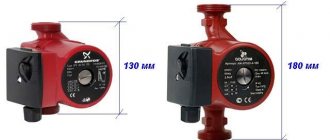
Of the geometric dimensions, the cross-section of the pipes (and, accordingly, the inlet and outlet pipes of the pump) and the distance between the pipes (installation length) are important. Depending on these parameters, a pump with a nominal pipe bore is selected, usually equal to 15, 20, 25 and 32 mm. Also, as a rule, there is a choice of two standard sizes with an installation length of 130 and 180 mm. At the same time, do not forget that a compact pump can always be installed instead of a model with a larger installation length, but installation, on the contrary, may cause difficulties.
Vertical or horizontal installation
Many modern pump models have a universal design and can be installed in any position.
But for some models it is important how the main axis of the pump is located - vertically or horizontally (check the type you need in advance, before purchasing)
ShutterStock
"Gilex"
Circulation pump, model “Tsirkul 25-40” (“Dzhileks”).
Leroy Merlin
Circulation pump, model Oasis 25/8 180 mm (RUB 2,911).
Leroy Merlin
Circulation pump, model Grundfos UPS 25/40 180 mm (RUB 5,044).
Wilo
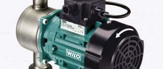
Circulation pump, Wilo-Stratos PICO-SmartHome series.
Coolant temperature
Approximately half of the models are designed for pumping clean water, usually with a temperature of at least 2°C. If you plan to use a coolant based on ethylene or propylene glycol, choose a model designed for the corresponding liquids, whose minimum temperature can be -10-15 ° C (this is indicated in the equipment description).
In addition, other requirements are imposed on the circulation pump. It is also desirable that it be economical and low noise. Economical - because even a small difference in the level of energy consumption (50-70 W) due to the length of the heating season gives savings on average up to 15-20 thousand rubles. per season. And a low noise level is necessary when placing pumping equipment near residential premises.
Based on cost, circulation pumps can be divided into two groups. The first is products from market leaders with a long-standing reputation, such as Grundfos, Wilo or DAB. The second group is Russian or Belarusian equipment, such as Gilex or Kalibr, or products from Chinese brands such as Oasis. The choice between the two groups depends on the needs of the buyer. Leaders' products are preferable when it is necessary to create a reliable and durable system that will work for a long time. Pumps of the second group are suitable for building a basic economical solution.
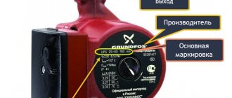
Features of equipment marking
Unfortunately, there are no standardized requirements for the labeling of circulation pumps. Manufacturers independently choose a list of technical characteristics that are indicated on the device body.
When purchasing a pump, you should not rely only on the markings. It is better to open the instruction manual and read the technical specifications there
The front panel typically displays the following information:
- direction of coolant movement;
- diameter of connected pipes;
- maximum permissible pressure;
- manufacturer and model;
- maximum operating temperature;
- degree of protection;
- operating parameters of the electrical network;
- marks of compliance with national technical regulations.
Manufacturers may provide other information at their discretion. Detailed technical characteristics of the devices are indicated in the operating instructions.
Units of measurement vary from country to country, so the numbers on the case can be deceiving. It is better to once again open the instructions, where, along with the characteristics, their units of measurement are also indicated.
