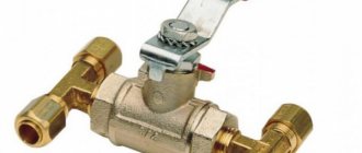
In heating systems, where heaters and coolers are used in the piping units, a characteristic type of fittings is found - a two-way valve. The device quickly and accurately regulates the volume of water supply and withdrawal. It is in demand in heating, ventilation and air conditioning systems. Nowadays, two-way valves equipped with an electric drive and controlled by special sensors are in great demand. These are reliable and easy-to-install devices, the design features and differences of which we will learn below.
Two way valve
Purpose and design
The classic configuration of the device is as follows:
- thermostatic valve;
- thermal head with remote sensor;
- thermal head valve;
- limit sensor that takes into account temperature;
- meter;
- circulation pump;
- water filter;
- check valve
Two-way adjusters are used everywhere, but a lot depends on what material they are made of. Considering the design features, we will immediately make a reservation that valves come with one or two seats. Using the second type, the flow of the working medium is regulated and blocked, and significant pressure drops are allowed, which a valve with a single seat cannot cope with. The valve itself looks like a separate part with a mechanical or electronic drive. It happens that an additional energy source is not provided, so it is installed after installation of the device.
*
Advantages of a two-way valve:
- simple design;
- easy to install;
- does not require human involvement to work effectively;
- repairable;
- reliable;
- lasts a long time;
- hermetically sealed;
- characterized by low hydraulic resistance;
- available.
Paying attention to the design of the element, it will seem that it is similar to a standard valve, but the mechanisms differ significantly. For example, the main closing element of a valve is a stem or ball. That is, a rod located in a horizontal or vertical position, or a ball rotated around its axis by 90 degrees, is responsible for limiting the flow of water. The device operates according to a simple scheme - a special hole opens and liquid is transported through it. In order for these structural elements to function, an actuator is connected to the valve, which requires electricity or compressed air. The drive itself is combined with separate instruments that take into account pressure in the system, temperature and other characteristics.
Valve design
Operating principle of a two-way valve
The main feature of the two-way fitting is that the supply volumes can be adjusted only in the direction of flow along the arrow indicated on the body. The flow is not adjusted in the reverse direction; such a connection may lead to failure of the device.
The flow rate is changed by turning or lifting the shut-off element, which is done by the valve handle, or using an electromagnetic drive.
Diagram of a two-way valve
When the shut-off element is completely closed, the flow of the working medium stops, and the system behind the valve is completely sealed. To prevent various abrasive particles from damaging the mirror surface of the lock, it is recommended to install a filter in front of the entrance.
Areas of use
*
As noted above, this type of control valve is used in heating, ventilation and air conditioning systems. We will separately consider the features of its use in a circuit with a “warm floor”.
If a boiler is installed in the house, then its task is to heat water and, as a rule, its temperature is quite high, suitable for radiators (from +75 to +95 degrees Celsius). For a “warm floor” system, such heating is not needed, since sanitary standards regulate a maximum of +35 degrees Celsius. This indicator is enough to comfortably walk on the floor covering. If the temperature is higher, this will not only cause inconvenience to residents, but will also negatively affect the finishing floor covering. For example, linoleum or laminate are easily deformed.
The “warm floor” is installed under the screed; in addition, different flooring materials are used. To do this, the coolant is heated to +50 degrees Celsius. When a heated floor is directly connected to a boiler or centralized heating system, the resulting temperature is too high. To reduce it at the entrance to the circuit, install a mixing valve for a warm floor, with a two-way or three-way tap already provided. Based on the name, the purpose of such fittings is to mix hot and cold water circulating along the circuit. That is, the process of fluid passage changes - for the radiator, the water remains hot, but the already mixed water, which has a lower temperature, is supplied to the warm floor.
Installed valve
Dividing type
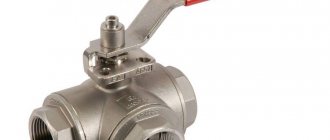
The dividing type of three-way valve is designed to separate the main flow into two parts. For this purpose, the device has two outlets and one inlet. This option is required to distribute the coolant flows into two flows. If you include boilers and convectors in the system, then you cannot do without such a valve. A separation type valve functions in a hot water supply system to separate the liquid. Quite often it is used in air heater piping.
What materials is it made from?
*
Cast iron, brass and steel products are now common. For example, fittings made of cast iron and steel are installed in pipeline systems with large flows of water or steam. Brass valves are often found in ventilation systems. Their main advantage is their compact size, so the element can be installed even in small rooms with limited water consumption.
It is recommended to use a steel or cast iron control valve. Steel products are common, which are just as strong as their cast iron counterparts, but are much cheaper. When choosing a material, the pressure characteristics in the system and the dimensions of the fittings themselves are taken into account.
Steel valve
Types of control valves
*
Reinforcement differs in several ways.
Depending on the design features, there are 2 types:
- walk-through - in them the pipes have the opposite arrangement;
- angular - located at an angle of 90 degrees.
Pay attention to how the valve is controlled.
According to this parameter, there are 3 types:
- pneumatic;
- hydraulic;
- equipped with electric drive.
The electrical drive device is a low-power electric motor or retractor solenoids. Of course, there are products with manual control, but they are more difficult to operate, since they do not allow you to set precise parameters. The devices operate from an electrical network with alternating current 220 V or direct current 24 V.
Certain pass-through units operate in autonomous mode, without power supply. Such fittings are controlled and regulated by means of a membrane and a counteracting spring. As feedback, a circuit is used along which the coolant moves - it also directs the membrane in the desired direction.
What does a two-way valve provide:
- consumption is regulated, resources (water) are distributed and saved;
- more economical heat consumption;
- equipment and networks are protected from pressure surges;
- If used correctly, the valve extends the life of the connected equipment and the network itself.
The devices are mounted using flanges, threads or welding. One of the subtypes of a threaded connection is a pin-type fastening, in which the valve is screwed into another device. When the installation is welded, special pipes are used.
We will separately highlight the valve with remote control, which is the easiest to operate. Such devices are complemented by electric drives or remote controls. It is the control rooms that accept all the current characteristics and parameters of the system. The pressure decreases remotely, the pressure increases, or certain branches of the heating network are blocked.
A type of two-way valve
Design differences between devices
Depending on the shape of the device body, there are:
- straight, installed on straight sections of pipelines;
- angular, with a rotation of 90 degrees;
- two-valve, in the event that it is necessary to sum two flows into one, then during assembly a tap with two valves is installed.
Two-valve device
Two-way fittings by type of control:
- Adjustment is made using the handle. For large pipeline diameters, a flywheel with a gearbox is used to smoothly regulate the flow.
- With remote electrical control. There are two types with a solenoid valve or with an electric motor. The solenoid valve is installed on small-diameter taps, and the electric motor on main pipelines. Smooth flow control and closing in an emergency are possible.
- Adjustment using a pneumatic drive. A pneumatic cylinder is installed on the fitting, with the help of which, when air is supplied, closing or opening occurs. The disadvantage of such a system is the need to wire an air line.
Connection diagram
*
For water heated floors, the valve is most often installed in a parallel circuit. To implement it, 2 or 3 heating circuits with circulating coolant must be used. The water supply and pressure is regulated by one or more valves installed in parallel. When mixing the coolant in parallel, you should disconnect the heated floor lines in advance.
As a rule, control taps are adjusted independently, manually, where the required volume of water flow is set.
Important! If a parallel circuit is used, it is recommended to replace the bypass with a bypass valve. This is done in order to reduce the operating load and save electricity supplied to the pump.
The circuit has a minus - the coolant entering the circuit will be the same temperature as the water leaving the return circuit to the boiler. Because of this, hot water is distributed unevenly along the circuits.
Installation diagram for heated floors
Installation Features
The procedure itself boils down to connecting the valve to the necessary pipelines. In order for the fittings to work for a long time and without problems, the connection should be implemented correctly, taking into account all the tips and recommendations. If you lack experience, it is recommended to contact specialists. Otherwise, the heating system will not be as efficient and economical as it should be.
Before starting installation work, pay attention to the two-way valve - its body has an external or internal thread onto which the union nut (or fitting) of the pipeline is screwed. For a reliable connection, experts advise wrapping the thread with a sealant, which can be used as FUM tape.
The fittings are supplied with special gaskets that ensure the proper level of tightness. If these are not available, then you will have to purchase them separately, of the appropriate thickness and diameter. The main task is to ensure a tight connection, without distortions on the threads, which will prevent possible leaks. No special tools or devices are required.
Note! Two-way valves do not operate under the simplest conditions, namely under the influence of high temperatures. Because of this, threaded connections may lose their tightness, so the connection procedure must be carried out responsibly.
Expert advice:
- During installation, ensure that there is no force in the piping.
- Before installing the element on the water supply system, the latter should be thoroughly cleaned, removing all impurities. They negatively affect the condition of the sealing materials, which leads to the valve’s tightness being compromised.
- Over time, the device may need to be repaired or dismantled, so it is necessary to leave enough free space around it.
- It is important to carry out careful installation. If a flange connection is used, it is recommended to tighten the corresponding screws alternately to avoid internal stress. With the threaded installation method, adjustment links are used, which will allow the valve to be dismantled in the future.
- If you need to blow out or flush the entire pipeline system, the valve is removed and an adapter is installed in its place.
Installation is a complex process and largely depends on the chosen scheme. To avoid mistakes, we recommend ordering valve installation services from specialists.
Valve in the heating system
How to choose
When choosing a three-way valve, it is very important to understand several indicators.
When choosing, it is advisable to enlist the help of a skilled plumbing engineer. First of all, it is necessary to evaluate the purpose of the device - separating or mixing. The next step is to determine the installation location on the system diagram, as well as the method of controlling the device. If automated heat supply control is intended, you need to decide how this faucet will be controlled - by an electric drive, a thermostat, or manually.
The following technical properties are subject to further analysis:
- Highway capacity. This is the volume of liquid passing per unit of time. The capacity of the crane must be no less. A very small clearance will create unwanted flow resistance and complicate the operation of the entire system.
- Maximum and working pressure. It must also meet the design values for the heating system.
- Connecting dimensions. If an exact match of the diameters cannot be achieved, then adapter fittings are used.
- Operating temperature adjustment range.
Guided by the listed parameters, it is necessary to select from dozens of offers on the market several models that meet the specified requirements.
At this step, it is time to compare the price, warranty period, availability of service and, of course, the reputation of the manufacturer. Guaranteed quality is provided by such market leaders as:
- Honeywell. The American company has been creating, supplying, installing and operating a wide range of elements and entire control systems for heat supply, ventilation, and security for the second century.
- Esbe. The Swedish company has also been supplying precise and extremely reliable valves, fittings and system components for over a hundred years, specializing in heating technology. Scandinavian traditions of diligent and high-quality work are combined with technological approaches to design.
- Valtec is a Russian-Italian company that positively combines great Italian quality with a seven-year guarantee and good prices. Completely localized production with a European quality control system has not long appeared on the market, but has already managed to gain popularity.
There are also many suppliers on the market that have not yet achieved such an impeccable reputation. Saving on the price of the valve can subsequently lead to its unstable operation, very high costs, or even failure of the entire system.
In most cases, when installing three-way valves, one of the standard, well-developed schemes is selected.
Gravity manifold or hydraulic separator
In such a scheme, a pump is provided in circuit No. 2 to ensure circulation of the coolant. Its designation is two blue equilateral triangles connected at the vertices.
Figure 10. Installation diagram with gravity manifold
Direct connection to the heat source
Important! If the tap is connected specifically to an indirect heating water heater on the bypass, connected to pipe section B, in front of the device to determine the pressure value, you will have to assemble a valve with a hydraulic resistance equal to the resistance of the heat source
Figure 11. Direct connection to source
In another case, fluctuations in the coolant flow rate in section AB will begin. They will be caused by stem vibrations.
Differential pressure regulator
In case of high pressure from the heat source, a manometric throttling regulator is installed between the pressure manifold and the valve, compensating for the excess pressure of the coolant.
Figure 12. Circuit with throttling regulator
Professionals also use other connection schemes, based on the purpose of the system and the relationship between the indicators of the heat source, pipeline system, valve and consumer.
