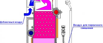
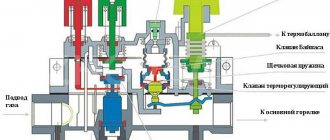
Draft is a characteristic that displays the rate of air exchange in the boiler. The gas combustion process requires a continuous supply of air and removal of combustion products (carbon monoxide, carbon dioxide, soot and water evaporation) into the atmosphere.
Types of traction:
- natural;
When burning, the air rushes upward according to the laws of physics and has a high temperature. This ensures the removal of combustion products and the natural flow of air due to its vacuum at the combustion site.
Boilers with natural draft are simple in design, less noisy and do not require additional electricity consumption.
- forced.
This type of draft is carried out due to the forced flow of air into the burner from a blowing device.
It is also controlled by an electronic control system.
Air is taken from the room or from the atmosphere. In the second case, a coxial pipe is often used.
Its design includes outer and inner pipes of different diameters. Through the outer pipe, air is sucked in for its forced supply, and through the inner pipe, carbon monoxide is released.
Boilers with forced draft and coxial tube necessarily have a sealed type of combustion chamber. Their advantages:
- safety, unlike an open combustion chamber;
- high boiler efficiency;
- does not consume oxygen in the room;
- For the boiler to operate, only one hole in the wall is required.
However, there are a number of disadvantages:
- complexity of the design, and, consequently, more complex maintenance and repair;
- noise due to the operation of the electric motor of the inflatable device;
- the need for continuous power supply.
Traction sensor
Definition
The autonomous operation of the gas boiler is carried out thanks to an electronic control system. It provides control using sensors, collecting technical indicators from different parts of the structure. If these indicators deviate from the norm, the control system changes the boiler operating mode or stops its operation.
A gas boiler draft sensor is a monitoring device that determines the presence and degree of draft in the chimney, and also transmits the corresponding signals to the electronic boiler control system.
It is the main device that protects the health and lives of people from the accumulation of carbon dioxide indoors.
What is it needed for
The main functions of the draft sensor are to determine the draft force and completeness of gas combustion, as well as ensure safety during operation of the gas boiler by sending a signal to the control system about insufficient draft.
If the process of removing carbon monoxide is disrupted, it accumulates in the room, which negatively affects human health, and, with a large volume of accumulated combustion products, poses a serious threat to human life.
The draft sensor detects and prevents incorrect operation of heating equipment.
Where is it located?
Installing a draft sensor in gas boilers is a prerequisite for their operation. This is approved by the relevant legislative act.
As a rule, the installation location of the sensor is the smoke hood or a section of the boiler body near the ventilation duct.
The draft sensor is not installed by the manufacturer directly into the flue or is separated from it by a special thermal insulating material. This type of installation eliminates overheating of the draft sensor due to direct contact with a hot surface.
The draft sensor, like the chimney, requires periodic inspection and cleaning.
Where to install
DT is set extremely close to the controlled parameter. So in double-circuit boilers they are placed on the return line before entering the boiler, at the outlet from it in the supply pipeline, at the outlet from the unit in the DHW circuit.
DT for monitoring the outgoing temperature of flue gases is installed at the outlet of the boiler in front of the mouth of the chimney. Wireless diesel engines for the boiler unit are placed directly on the controller or on the gas shut-off valve. Wired - connected by the option designated by the equipment manufacturer.
Device and principle of operation
The main principle of operation of a gas boiler draft sensor is the closing and opening of contacts.
It works according to the laws of physics, thereby controlling the temperature of the burned fuel. When the temperature indicator shifts into an unacceptable zone, the draft sensor transmits a corresponding signal to the electronic control unit of the boiler.
The type of sensor directly depends on the type and design of the gas boiler in which it is installed.
Boiler with natural draft and open combustion chamber
The main element is a plate consisting of two metals that have different deformation characteristics due to heating, as well as two contacts that are brought together and separated by these plates. As a rule, one of these plates is fixedly fixed to the sensor body, and the second is deformed due to thermal effects.
The sensor must match the fuel type. If the boiler operates on compressed natural gas, the sensor must operate in the temperature range from 95 to 950 °C, if on liquefied gas - from 75 to 1500 °C.
If the traction force becomes less, burnt gases accumulate. Due to this malfunction, the temperature of the measuring device increases. The bimetallic plate opens the contacts and the gas supply to the burner stops, that is, the boiler control unit performs an emergency shutdown.
Work will resume when the sensor cools down and its temperature drops within the appropriate range. This means that it also acts as a thermostat.
With forced draft and closed combustion chamber
In this case, the draft sensor has a pneumatic relay design with a very sensitive membrane. The blowing device creates strong draft and movement of burnt gases. Under their influence, the membrane is deformed and closes the sensor contacts. At this time, the control unit detects normal operation of the boiler with sufficient draft.
But, with insufficient traction, there is not enough force to displace the membrane and it returns to its original position. The contacts open and the heating device stops operating.
With condensing heating type
The sensors, as on boilers with natural draft, operate on the principle of deforming a bimetallic plate, but are set by the manufacturer to a lower temperature regime.
Where can I buy
Electronics for heating boilers are available for purchase in specialized stores in your city. But there is another option that has recently received significant improvements. You no longer need to wait a long time for a parcel from China: the AliExpress online store now offers the opportunity to ship from transshipment warehouses located in various countries. For example, when ordering, you can specify the “Delivery from the Russian Federation” option.
Follow the links and choose:
| Thermostat for gas boiler with Wi-Fi and remote control, 3A | Smart Wi-Fi thermostat Tuya for boiler | Smart Wi-Fi Touch Thermostat, Wireless |
| Digital LCD Thermometer with Water Temperature Gauge | Thermostat for gas boiler TUYA, wireless | Intelligent Thermostat, Temperature Controller |
When and why it works
There are a number of reasons why the draft in a gas boiler is disrupted and the sensor is triggered:
- improper design of heating equipment;
The reason that you first need to pay attention to. It implies an incorrect design of the chimney, the presence of bends, or poor-quality installation.
- chimney obstruction;
Gas boilers leave much less soot, unlike solid fuel boilers. Despite this, over a longer period of time, soot tends to accumulate in gas boilers, which is the reason for poor chimney permeability.
The next reason for a clogged chimney can be foreign objects, such as leaves, tree branches, and flying debris.
It is extremely rare for animals to get into the chimney. Often these are birds that make nests on the chimney during the non-heating period or during the absence of people and the boiler has not been working for a long time.
The chimney requires periodic inspection and, depending on the degree of contamination, mechanical cleaning.
- weather;
Moscow is a city of frequent changes in weather conditions.
The cause of shutdowns may be dense fog, heavy precipitation, or simply high humidity. This creates high atmospheric pressure, which is an obstacle to air exchange.
Strong winds also create high pressure in the atmosphere. It can harm natural draft and contribute to the reverse movement of combustion products (backdraft).
Bad weather conditions can only harm the operation of boilers with natural draft and an open combustion chamber.
It is advisable to install a protective cap on the chimney. Its name is traction stabilizer.
It prevents wind from blowing into the air duct and prevents the burner from extinguishing.
- airlock;
Smoke removal requires continuous movement of air masses. An air lock in the chimney can interfere with air exchange and cause combustion products to flow back.
An air lock occurs due to poor-quality thermal insulation of the chimney and a large temperature difference in its lower and upper parts. At the top it is usually cold, heavier and thicker.
- insufficient height and incorrect installation location of the chimney;
It depends on the distance of installation of the pipe from the highest point of the roof - the ridge of the roof. The ideal location is the middle of the roof side and the height above the ridge is about 50 cm.
- Unstable voltage level in the electrical circuit.
Power surges can negatively affect the operation of all electronic components of heating equipment.
If the sensor is triggered and the boiler is turned off, it is not recommended to force it to start again. This will damage the heating equipment and increase the danger to human health and life. In such cases, diagnostics, identification and elimination of the causes of the malfunction are necessary.
Features of the use of the most common thermocouples
Technical characteristics depend directly on the materials from which they are made.
Type J (Iron Constantan Thermocouple)
- It is not recommended to use below 0°C, because Moisture condensation on the iron terminal leads to the formation of rust.
- The most suitable type for rarefied atmospheres.
- The maximum temperature of use is 500°C, because Above this temperature, rapid oxidation of the leads occurs. Both terminals are quickly destroyed in a sulfur atmosphere.
- The readings increase after thermal aging.
- Low cost is also an advantage.
Type E (chromel-constantan thermocouple)
- The advantage is high sensitivity.
- Thermoelectric homogeneity of electrode materials.
- Suitable for use at low temperatures.
Type T (copper-constantan thermocouple)
- Can be used below 0°C.
- Can be used in atmospheres with slight excess or deficiency of oxygen.
- Use at temperatures above 400°C is not recommended.
- Not sensitive to high humidity.
- Both leads can be annealed to remove materials causing thermoelectric inhomogeneity.
Type K (chromel-alumel thermocouple)
- Widely used in various areas from -100°C to +1000°C (recommended limit depending on the diameter of the thermoelectrode).
- In the range from 200 to 500°C, a hysteresis effect occurs, i.e., readings during heating and cooling may differ. Sometimes the difference reaches 5°C.
- Used in a neutral atmosphere or an atmosphere with excess oxygen.
- After thermal aging, the readings decrease.
- It is not recommended to use in a rarefied atmosphere, because... chromium can be released from the Ni-Cr terminal (so-called migration), and the thermocouple changes the thermoelectric force and shows a low temperature.
- A sulfur atmosphere is harmful to a thermocouple because affects both electrodes.
Type K thermocouple.
Type N (nicrosil-nisil thermocouple)
- This is a relatively new type of thermocouple, developed from the K-type thermocouple. The K-type thermocouple can be easily contaminated by impurities at high temperatures. By fusing both electrodes with silicon, the thermocouple can be precontaminated and thus reduce the risk of further contamination during operation.
- Recommended operating temperature up to 1200°C (depending on wire diameter).
- Short-term operation is possible at 1250°C.
- High stability at temperatures from 200 to 500°C (significantly less hysteresis than for a type K thermocouple).
- Considered to be the most accurate base metal thermocouple.
General Tips for Selecting Base Metal Thermocouples
- Application temperature below zero – type E, T
- Room temperatures for use – type K, E, T
- Application temperature up to 300°C – type K
- Application temperature from 300 to 600°C – type N
- Application temperature above 600°C – type K or N
Precious metal thermocouples
Recommended maximum operating temperature 1350°C. Short-term use is possible at 1600°C. It becomes contaminated at temperatures above 900°C with hydrogen, carbon, and metallic impurities of copper and iron. When the iron content in the platinum electrode is 0.1%, TEMF changes by more than 1 mV (100°C) at 1200°C and 1.5 mV (160°C) at 1600°C. The same picture is observed with copper contamination. Thus, thermocouples should not be reinforced with steel tube, or the electrodes should be insulated from the tube with gas-tight ceramics. Can be used in oxidizing atmosphere. At temperatures above 1000°C, the thermocouple may become contaminated with silicon, which is present in some types of protective ceramic materials
It is important to use ceramic tubes consisting of high purity aluminum oxide. It is not recommended to use below 400°C, since the thermoelectric force in this region is small and extremely nonlinear.
Precious metal thermocouples
The properties are the same as those of type S thermocouples.
It will be interesting What is a short circuit
Type B (platinum-platinum-rhodium)
Recommended maximum operating temperature is 1500°C (depending on wire diameter). Short-term use is possible up to 1750°C. Can be contaminated at temperatures above 900°C by hydrogen, silicon, copper and iron vapor, but the effect is less than for S and R thermocouples. At temperatures above 1000°C the thermocouple can be contaminated by silicon, which is present in some types of protective ceramic materials
It is important to use ceramic tubes consisting of high purity aluminum oxide. Can be used in oxidizing environments. Application is not recommended at temperatures below 600°C, where the emf is very small and nonlinear. Summary table of thermocouple types
Summary table of thermocouple types.
Diagnostics
Before you check the draft sensor of a gas boiler, you should know: boilers equipped with an electronic control system independently diagnose the faulty unit and report an error.
However, if the model is not equipped with a control system, it is possible to independently check the condition of the boiler and identify a malfunction of the draft sensor based on the following signs:
- constant independent shutdown of the boiler during the operating cycle with normal combustion, no overheating and normal draft;
- no automatic restart after one cycle of operation (10–30 minutes).
- In order to perform independent diagnostics of the air exchange control system and identify its possible malfunction, you must:
- install a mirror to the location where the draft sensor is installed and start the boiler. There should be no traces of fogging on it;
- covering the damper in the chimney. If the smoke removal control system is working properly, the boiler will turn off on its own due to smoke accumulation and overheating;
- in case of automatic stop of the boiler operating in hot water supply mode and when the hot water tap is open. This is a sign of a faulty traction sensor.
Traction regulator functions
The main task will become clear if you look at the name of the device.
If you do not regulate the temperature of the coolant (water jacket), it will simply boil. Without an automatic regulator, you will either have to constantly add liquid or manually control the flow of air entering the firebox. The traction regulator greatly simplifies the life of private home owners. In addition to control, it performs two more useful functions:
- setting and maintaining the maximum permissible water temperature without boiling (up to 90° C; this is especially true in autumn or early spring);
- fuel economy (when the damper is closed, the intensity (speed) of firewood combustion decreases (albeit due to a decrease in boiler efficiency)).
Installing a draft regulator on a solid fuel boiler involves certain costs. To save money, some use a safety valve for similar purposes. For some reason it is considered an analogue of a regulator.
The solution is not the most rational, since after only 3-4 operations (turning off the boiler if there is a risk of overheating and reactivating it if there is excessive cooling), the accessory begins to leak.
Checking with a multimeter
This diagnosis requires some experience, knowledge of the electrical circuit of the boiler, as well as an understanding of how the draft sensor works in a gas boiler.
The reason for a malfunctioning air exchange control system, or if there are all signs of its malfunction, may be a violation of the integrity of the electrical wiring. In this case, the sensor may be working properly.
In this situation, it is necessary to inspect the wiring and connection points for integrity and absence of oxidation, as well as diagnostics with a multimeter. With its help, the electrical wiring is “ringed” and its faulty section is identified.
The tester can also diagnose an internal malfunction of the sensor itself. Normally, its resistance is 1–2 ohms. If the readings are 0 or infinity, the traction sensor is faulty.
The manufacturer does not recommend disassembling or repairing this device. The only way out is to replace it.
Repair
Self-repair of damaged boiler automation is not only unpleasant, but most often almost hopeless, since boiler passports are not written for these purposes. And without an exact knowledge of the circuit and all the intricacies of the automatic system design, it is better for a common person (not an electronics engineer) not to even start. Of course, I will not be opening America if I say that the best solution would be to initially buy a boiler with reliable automation from a reputable manufacturer, so you risk running into trouble less.
To control pumps, stations and other water supply devices, it is necessary to use special devices. A differential water pressure switch for the pump allows you to automatically turn off or turn on the pump when the pressure in the system changes.
How to disable
The instruction manual does not contain information on how to disable the draft sensor in a gas boiler. It does not recommend disabling this security system yourself. This can lead to negative consequences both for the device and for human health, since the activation of the sensor is a clear sign of danger.
Disabling the draft sensor is a direct violation of the safety rules established by the heating equipment manufacturer!
Carbon monoxide poisoning has the following symptoms:
- mild degree - headache, dizziness, chest pain, pounding in the temples, cough, lacrimation, nausea, vomiting, possible hallucinations, redness of the skin and mucous surface, rapid heartbeat, hypertension;
- moderate - tinnitus, drowsiness, paralysis;
- severe - loss of consciousness, convulsions, involuntary defecation or loss of urine, abnormal breathing rhythm, blue skin color, death.
The consequences of carbon monoxide poisoning can negatively affect a person’s future life activities.
At the same time, the boiler design allows for the possibility of turning off this system. To do this, it is necessary to disconnect the thermocouple breaker and the electrical wiring of the draft sensor from the solenoid valve, as well as from the electronic control unit of the boiler.
Thus, the control unit will continue to autonomously control the operation of the boiler, without taking into account the temperature of the burned gas and the force of its release into the atmosphere.
Principle of operation
The sensor alloy changes conductivity at different temperatures. Resistance decreases as it increases, and increases as it decreases. Electrical parameters change, which is recorded by the circuit.
The microcontroller of the serviced device, based on the received data, taking into account the specifications of the detector, calculates the t° shifts. Then it sends a signal to the executive unit (relay, heater, cooling system) to act at a particular t° level.
Example: taking into account the described algorithm, the voltage is controlled at the input of the thermostat comparator, adjusted according to the temperature characteristic, and it undergoes changes.
The NTC sensor itself is not an electronic device, it only records. It is based on a nonlinear dependence of resistivity. resistor depending on the temperature of the environment. The operating scheme may be simpler: a simple output on a value display or a relay can react immediately.
Sensors are sensitive to electromagnetic radiation and fields, so they are shielded or mounted at a distance from the sources of such phenomena (power wires).
How to troubleshoot
If a fault is detected in the gas boiler draft sensor itself, it is replaced with a new one. If a break or fault in the electrical wiring was detected using the tester, the corresponding section of the wire must be replaced or repaired.
After performing the above steps, it is necessary to re-check the operation of the boiler and the draft sensor by forcing it.
It is important to note that during the operation of any type of boiler, its periodic maintenance is mandatory and recommended by the manufacturer. It includes checking the electronic control unit, control devices, as well as the mechanical parts of the boiler. In addition, the components of the boiler and chimney are cleaned from accumulated combustion products.
For this purpose, qualified workers with appropriate education and diagnostic equipment corresponding to the characteristics of a particular type of boiler are involved.
Criterias of choice
The selection of a temperature sensor should be carried out taking into account the following criteria:
- range of measured temperatures, the sensor must be as sensitive as possible and respond to heating changes with minimal delay,
- technical features of the installation: submersible or fixed, is there enough space for installation, etc.,
- measurement conditions under which it is possible to minimize negative influencing factors,
- characteristics of the sensor: the need for voltage supply, the speed of the transmitted signal, the measurement error, the admissibility of operation in specific conditions,
- service life, maintenance periods, need for calibrations,
- output signal value.
Immersion temperature sensor for boiler
Schemes, connection
Schemes are used for homemade products and assemblies. This question, like calculations during selection, is a separate large topic, so we will describe only the basics to orient the reader.
Circuit diagram for ATmega and Arduino (programming will also be required):
The assembly below uses a TH10K thermistor and a 10k ohm resistor as R (balance):
Another diagram:
Standard sizes
Standard sizes of thermistors themselves: rods, tubes, disks, beads, plates, drops, tablets. Sizes 1–10 µm to several mm and 1 cm.
There are also SMD formats and micro-rectangles.
We can immediately distinguish between the sensors as ready-to-use products and the “bare” thermistors themselves.
Sensors as devices can be made in any form, housing according to the manufacturer’s decision, for example, probes, probes, “chips” with connectors, in a waterproof housing, with threads, on a long cable.
Sensors as ready-made devices
Automotive:
Invoices. On the surface of structures. Examples: T2C-NTC 10K for −50…+150° C; ALTF02 S+S for collecting data from solid objects (pipes).
Channel, submersible. For cavities. T3-NTC 10K with 30 cm cable, for +50…−50° C; T2I-NTC 10K, 6.5 cm, −50…+150° C; TF43T and TM54 for liquids in pipes and containers.
External. For weather-sensitive complexes, on external walls (ATF01 S+S Regeltechnic).
Rooms. For interior spaces, apartments, offices.
Multifunctional. They combine other sensors to study not only temperature, but also pressure, density, etc.
Beaded
Beads, ball, drop, Ø 0.075 to 5 mm. Made of lead wires, an alloy with platinum, sintered in a ceramic, glass-ceramic shell. Better response and stability, their operating temperatures are higher than those of disk variants and chips.
Disadvantages: higher fragility, no interchangeability, require individual calibrations. There are no exact standards for their R/T ratings.
Discs, records, chips, tubes
Disc-shaped products with surface contacts. The shape is larger, the reaction is slower than that of balls. But due to their increased dimensions, they have good dissipation (power to increase temperature by 1 degree). Since the energy dissipated is proportional to the square of the current, they work better with high currents than balls.
Disc ones are made by pressing powder-like oxides into a round matrix, then sintered. Chips are injection molded, the suspension is distributed into a thick ball, then dried and cut. Dimensions Ø 0.25…25 mm.
Interchangeable, but there are errors, the minimum permissible deviation is considered to be at least 0.05 ° C within 0...+70 ° C. A standard 10 kOhm thermistor within the range of 0…+100 has coefficients close to the following:
Tube thermistor:
Encapsulated
Encapsulated ones resemble wafers, tablets, and may be similar to other types. The peculiarity of their coating is that it is especially sealed, airtight (bubble, capsule, container), made of fiberglass. For high temperatures, from +150° C, for boards where special strength is required. This design increases stability, protection, Ø 0.4…10 mm.
Types of NTC thermistors
According to the range of values of the serviced NTC environment there are:
- low temperature. For below 170 K (Kelvin, maybe in Celsius);
- average, 170...510 K;
- high, from 510 K;
- ultra-high, 900…1300 K.
A separate type is combined, with indirect heating. They combine a resistor and a heating element “galvanically isolated” from it, which sets the temperature and, accordingly, the resistance. They are used as variable resistors controlled by the voltage supplied to their heating part.
Calculation, selection of NTC thermistors
They determine which thermistor is suitable by using the R/T curves, by creating graphs and tables of RT values, and by formulas. The procedure is complex, there are entire brochures and separate articles, so we will only indicate the basics.
The best, albeit complex, calculation formula is that of “Steinhart (Steinhart) - Hart”:
Calculations are usually done by radio electronics fans and specialists, especially for homemade products. It will be easier to select an element with a similar specification, and also use ready-made recommendations from specialists; the information is available online on special sites. There are hundreds of modifications of thermistors; accordingly, the specification tables are very large. Often a specific batch of similar series of thermistors has its own data.
There are hundreds of NTC thermistor specifications:
But still, calculations in most cases are extremely desirable, even if there is data from the manufacturer on the parameters and recommendations, since thermistors have highly nonlinear properties. Different copies of the same specification, even, for example, with the same values of B25/100 (sensitivity, we will consider below), may have different shifts R. Therefore, the formulas for this parameter provide only an approximate estimate. Accurate results require complex calculations.
Sensors for household or other appliances in factory standard sizes are devices in a housing that are completely ready for use, and so on, all the necessary calculations are made by the manufacturers.
Parameters for selection (usually displayed as graphs, diagrams):
- CVC;
- temperature/resistance ratio curve;
- heat capacity, dissipation constant;
- R values;
- tolerances;
- temperature Range. It is within their boundaries that NTC sensors can perform better than all similar products;
- time constant: the period for transition from one t° value to another. This is the period in seconds required to achieve 63.2% difference in t° from the initial reading to the final reading;
- sensitivity: level of response to temperature changes;
- stability of the controller while maintaining a constant temperature through feedback from the sensor.
First order approximation
The t°/Ohm dependence (RT graph) has significant nonlinearity, therefore, for practical circuits, so-called approximations are used for calculations. An example of such a “first order”:
The equation is valid only for a small temperature range and for t°, when k is almost constant at its different values.
Beta formula
There is also a beta equation (contains a constant "beta", β). This is the simplest formula that exists, often for homemade products, for example, this is what is used on Arduino. Gives results with an accuracy of ±1 °C. Covers the range 0…+100° C. The latter is dependent on a single material constant β, obtained by measurements (indicated in the thermistor specification).
There is no need to linearize the sensor response. The formula requires a 2-point calibration, typically no more than ±5 over the entire useful range.
Steinhart-Hart equation
The Steinhart-Hart algorithm is a better but more complex equation. To avoid complications, the previous method is usually used, but for users with algebra knowledge and calculation experience, this is the best method. This is the general formula to fit a thermistor curve:
The A, B, C constants are usually published by manufacturers and suppliers as part of thermistor specification tables. The deviation according to the described formula is about ±0.15° C within −50…+150° C, which is an excellent indicator. If high correctness is required, then the boundaries must be narrowed. The accuracy is ±0.01° C and is better observed within the range of 0…+100° C.
Which formula to choose
The selection of a suitable calculus for determining temperature from resistance measurements is based on the availability of computing power, and most importantly, on tolerance requirements. For some applications the 1st order approximation is sufficient, for other cases the Steinhart-Hart method is required and the sensor must be calibrated over a large number of measurements against a generated lookup table.
Adjusting parameters
When purchasing a sensor, the owner can proceed in various ways. It can leave the factory settings. This makes sense in cases where the pump operates under standard conditions.
If the design used has its own characteristics, then it is better to configure it yourself. How to do this is described in detail below.
After installation, it is necessary to adjust the minimum and maximum pressure values. It is important that the difference between them is approximately 1 atm. Before making adjustments, perform the following steps:
- All pump elements are disconnected from the network. Now you need to completely drain the water from the pump.
- You need to check the pressure level in the boiler. To do this, you can use any available pressure gauge.
- It is necessary that the pressure be equal to 1.5 atm. If it is less, you need to pump up water.
- If it is exceeded, you need to lower it by pressing the nipple.
Electronic pressure switch Source kty.com.ua
After the boiler has been prepared, it is necessary to begin the adjustment procedure. Here, as an example, we consider a mechanical type sensor. The adjustment is carried out as follows:
- To begin the adjustment procedure. The pump must be turned off. Then drain the water completely. Check the pressure gauge readings. It should show zero value.
- Start filling the boiler with water. When the process is completed, it is necessary to measure the pressure again. This value must be fixed.
- Now you need to drain the water to get the minimum pressure value. It is also fixed.
- Using a nut, the springs are approximately adjusted so that they correspond to the desired value. Weaken a spring with a smaller diameter. Using a nut, the compression of a larger diameter spring is adjusted. It must be remembered that when tightening it increases the minimum response pressure, and when unscrewing it decreases it.
- Fill the system with water, then drain it. It is necessary to determine the moment when the pump will automatically turn on. If it is more or less than required, additional adjustment of the spring is carried out.
- Start adjusting the spring with a smaller diameter. It is tightened to set the value at which the pump will turn off. Compression will lead to a decrease in the difference between the maximum and minimum pressure values, and weakening will lead to an increase in this parameter.
- Check the set values. To do this, start the pump and determine at what pressure value the shutdown will occur.
- If the maximum value is not set accurately, then by tightening or unscrewing the nut, adjust the degree of compression of a small diameter spring until the parameter is set accurately.
When the pressure thresholds are accurately set, the adjustment procedure is completed.
Gas boiler pressure switch Source stroy-podskazka.ru
Designation on the diagram
On the diagrams, NTC is indicated by a rectangle (empty) crossed out by an oblique line at the bottom with a horizontal leg; there is also a “t°” icon with a minus. PTC posistors have “+”.
Another designation option is a schematic image of a spiral (like the teeth of a cardiogram), crossed out by an oblique line with the same temperature symbol:

