At the stage of preparation for major repair work and in the process of planning the construction of a new house, it becomes necessary to calculate the number of heating radiator sections. The results of such calculations make it possible to find out the number of batteries that would be enough to provide an apartment or house with sufficient heat even in the coldest weather.
Calculation of the number of heating radiator sections
The calculation procedure may vary depending on many factors. Read the instructions for quick calculations for typical situations, calculations for non-standard rooms, as well as the procedure for performing the most detailed and accurate calculations, taking into account all sorts of significant characteristics of the room.
Calculation of the number of heating radiator sections
Recommendations for calculations before starting work
To independently calculate the required number of heating battery sections, you must know the following parameters:
- dimensions of the room for which the calculation is being performed;
How to measure a room - the power of the entire battery or each of its sections. This information is provided in the technical documentation supplied by the heating unit manufacturer.
Calculation of sections for CONDOR radiators
Heat transfer indicators, the shape of the battery and the material of its manufacture - these indicators are not taken into account in the calculations.
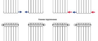
Important! Do not perform calculations for the entire house or apartment at once. Take a little more time and do the calculations for each room separately. This is the only way to obtain the most reliable information. At the same time, in the process of calculating the number of battery sections for heating a corner room, you need to add 20% to the final result. The same reserve must be added on top if there are interruptions in the heating operation or if its efficiency is not enough for high-quality heating.
How to clean cast iron batteries before painting
High-quality painting requires:
- preliminary cleaning from dust, rust and dirt;
- removing all layers of old oil;
- coating with a metal primer, preferably heat-resistant;
- painting in 2 layers gives the highest quality and smoothest surface (one layer can be slightly diluted with a solvent to save composition).
Many actions can be easily carried out using available tools, including brushes for cleaning and washing. Old paint can be removed using different methods (can be done in a complex way):
- chemical;
- mechanical (special attachments for grinders and universal tools);
- thermal (hair dryer, blowtorch);
- manually.
Advice! Use a metal brush to clean the surface before applying primer to remove loose particles that may then stick to the brush or roller.
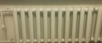
Old radiators after painting will last at least another decade
Not every paint is suitable for painting cast iron radiators. Only non-toxic heat-resistant enamels for interior use. They are sold in different forms - cans, jars, buckets. If you paint without a primer, you can degrease it with a solvent suitable for its chemical composition. Even if the enamel is “environmentally friendly”, when painting the area of a cast iron radiator MS-140 (another model) use:
- respirator,
- work gloves;
- work clothes and shoes.
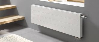
It is recommended to ventilate the room at each stage of processing, especially after the paint has set a little. All calculation data are adjusted to suit any modern model or an old one. The area of the heated surface varies slightly for 1K60P-60x500 “Barelief”, Standard-90, RD-90s, 2K60P-300, B-Z-140×300, MR-2KP140 “Bekard”, etc. How to carry out calculations, by the number of sections , on a “calculator” or through a program, decide for yourself. There won't be any big differences.
>Painting area of cast iron radiators
The beauty of the heating device can be easily restored by painting the surface of the cast iron radiator.
Standard calculation of heating radiators
Calculation of heating radiators
Let's start our training by considering the most commonly used calculation method. It can hardly be considered the most accurate, but in terms of ease of implementation it definitely takes the lead.
Standard calculation of heating radiators
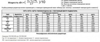
According to this “universal” method, 100 W of battery power is needed to heat 1 m2 of room area. In this case, calculations are limited to one simple formula:
K=S/U*100
In this formula:
- K is the required number of battery sections to heat the room in question;
- S is the area of this room;
- U – power of one radiator section.
Formula for calculating the number of radiator sections
As an example, let's consider the procedure for calculating the required number of battery sections for a room with dimensions of 4x3.5 m. The area of such a room is 14 m2. The manufacturer claims that each section of the battery it produces produces 160 W of power.
We substitute the values into the above formula and find that to heat our room we need 8.75 radiator sections. We round up, of course, i.e. to 9. If the room is corner, add a 20% margin, round up again, and get 11 sections. If problems are observed in the operation of the heating system, add another 20% to the originally calculated value. It will turn out to be about 2. That is, in total, to heat a 14-meter corner room in conditions of unstable operation of the heating system, 13 battery sections will be needed.
Calculation of aluminum heating radiators
Add a link to a discussion of the article on the forum
RadioKot >Articles >
| Article tags: | Add a tag |
Radiators and cooling.
Author: Published 04/28/2006
There is a well-known law in physics, electrical engineering and atomic thermodynamics - current flowing through wires heats them. Joule and Lenz came up with it, and they turned out to be right - that’s how it is. Everything that runs on electricity, one way or another, transfers part of the passing energy into heat. It just so happens in electronics that the most heat-suffering object in our environment is air. It is the heating parts that transfer heat to the air, and the air is required to take the heat and send it somewhere. Lose, for example, or scatter throughout oneself. We will call the process of heat transfer cooling. Our electronic designs also dissipate a lot of heat, some more than others. Voltage stabilizers heat up, amplifiers heat up, the transistor that controls the switch or even just a small LED heats up, except that it heats up just a little. It's okay if it heats up a little. Well, what if it’s so fried that you can’t hold your hand? Let's take pity on him and try to help him somehow. So to speak, to ease his suffering. Let us recall the device of a heating battery. Yes, yes, the same ordinary battery that heats the room in winter and on which we dry socks and T-shirts. The larger the battery, the more heat there will be in the room, right? Hot water flows through the battery, it heats the battery. The battery has an important thing - the number of sections. The sections are in contact with the air and transfer heat to it. So, the more sections, that is, the larger the occupied area of the battery, the more heat it can give us. By welding a couple more sections, we can make our room warmer. True, in this case, the hot water in the battery may cool down, and there will be nothing left for the neighbors. Let's consider the device of a transistor.
On a copper base (flange) 1
crystal
3
on substrate
2 .
It connects to pins 4
.
The entire structure is filled with plastic compound 5
.
The flange has hole 6
for installation on the radiator. This is essentially the same battery, look! The crystal heats up, it's like hot water. The copper flange is in contact with the air, these are the battery sections. The contact area between the flange and the air is where the air is heated. The heated air cools the crystal.
How to make a crystal cooler? We cannot change the design of the transistor, this is clear. The creators of the transistor also thought about this and for us martyrs, they left the only path to the crystal - the flange. The flange is like a single section of a battery - it fryes, but no heat is transferred to the air - the contact area is small. This is where we have room for our actions! We can extend the flange, solder a couple more sections to it, that is, a large copper plate, since the flange itself is copper, or we can fix the flange on a metal blank called a radiator. Fortunately, the hole in the flange is prepared for a bolt and nut.
What is a radiator? I’ve been repeating the third paragraph about him, but I haven’t really said anything! Okay, let's see:
As you can see, the design of radiators can be different, these include plates and fins, and there are also needle radiators and various others; just go to a radio parts store and run through the shelf with radiators. Radiators are most often made of aluminum and its alloys (silumin and others). Copper radiators are better, but more expensive. Steel and iron radiators are used only at very low power, 1-5W, as they dissipate heat slowly. The heat generated in the crystal is determined by the very simple formula P=U*I
, where P is the power released in the crystal, W, U = voltage on the crystal, V, I is the current through the crystal, A. This heat passes through the substrate to the flange, where it is transferred to the radiator. Next, the heated radiator comes into contact with the air and heat is transferred to it, as the next participant in our cooling system.
Let's look at the complete cooling circuit of the transistor.
We got two things - this is a radiator 8
and gasket between the radiator and transistor
7
. It may not exist, which is both bad and good at the same time. Let's figure it out.
I’ll tell you about two important parameters - these are the thermal resistance between the crystal (or junction, as it is also called) and the transistor body - Rpk and between the transistor body and the radiator - Rcr. The first parameter shows how well heat is transferred from the crystal to the transistor flange. For example, Rpc equal to 1.5 degrees Celsius per watt explains that with an increase in power by 1 W, the temperature difference between the flange and the radiator will be 1.5 degrees. In other words, the flange will always be colder than the crystal, and this parameter shows how much. The smaller it is, the better the heat is transferred to the flange. If we dissipate 10 W of power, then the flange will be colder than the crystal by 1.5 * 10 = 15 degrees, and if 100 W - then by 150! And since the maximum temperature of the crystal is limited (it cannot fry until white heat!), the flange must be cooled. At the same 150 degrees.
For example: A transistor dissipates 25W of power. Its Rpc is equal to 1.3 degrees per watt. The maximum crystal temperature is 140 degrees. This means that there will be a difference of 1.3*25=32.5 degrees between the flange and the crystal. And since the crystal cannot be heated above 140 degrees, we are required to maintain the flange temperature no hotter than 140-32.5 = 107.5 degrees. Like this. And the Rcr parameter shows the same thing, only losses occur on that same notorious gasket 7. Its value of Rcr can be much greater than Rpk, therefore, if we are designing a powerful unit, it is not advisable to place transistors on the gaskets. But still sometimes it is necessary. The only reason to use a gasket is if you need to isolate the heatsink from the transistor, because the flange is electrically connected to the middle terminal of the transistor body.
Let's look at another example. The transistor heats up at 100W. As usual, the crystal temperature is no more than 150 degrees. Its Rpc is 1 degree per watt, and it’s also on a gasket, which has Rcr 2 degrees per watt. The temperature difference between the crystal and the radiator will be 100*(1+2)=300 degrees. The radiator must be kept no hotter than 150-300 = minus 150 degrees: Yes, my dears, this is the very case that only liquid nitrogen will save: horror! It is much easier to live on a radiator for transistors and microcircuits without gaskets. If they are not there, and the flanges are clean and smooth, and the radiator sparkles with shine, and even heat-conducting paste is applied, then the Rcr parameter is so small that it is simply not taken into account.
Got it? Let's move on!
There are two types of cooling - convection and forced. Convection, if we remember school physics, is the independent distribution of heat. The same goes for convection cooling - we installed a radiator, and it will somehow deal with the air there. Convection-type radiators are most often installed outside of devices, like in amplifiers, have you seen? On the sides are two metal plate things. Transistors are screwed onto them from the inside. Such radiators cannot be covered, blocking the access of air, otherwise the radiator will have nowhere to put the heat, it will overheat itself and refuse to accept heat from the transistor, which will not think for a long time, it will also overheat and: you know what will happen. Forced cooling is when we force air to more actively blow on the radiator, making its way along its ribs, needles and holes. Here we use fans, various air cooling channels and other methods. Yes, by the way, instead of air there can easily be water, oil, and even liquid nitrogen. Powerful generator radio tubes are often cooled with running water. How to recognize a radiator - is it convection or forced cooling? Its efficiency depends on this, that is, how quickly it can cool a hot crystal, what flow of thermal power it can pass through itself. Let's look at the photos.
The first radiator is for convection cooling. The large distance between the fins ensures free air flow and good heat transfer. A fan is placed on top of the second radiator and blows air through the fins. This is forced cooling. Of course, you can use both radiators everywhere, but the whole question is their efficiency. Radiators have 2 parameters - their area (in square centimeters) and the radiator-to-medium thermal resistance coefficient Rрс (in Watts per degree Celsius). The area is calculated as the sum of the areas of all its elements: the area of the base on both sides + the area of the plates on both sides. The area of the ends of the base is not taken into account, so there will be very few square centimeters there.
Example: The radiator from the example above is for convection cooling. Base dimensions: 70x80mm Rib size: 30x80mm Number of ribs: 8 Base area: 2x7x8=112 sq.cm Rib area: 2x3x8=48 sq.cm. Total area: 112+8x48=496 sq.cm.
The radiator-medium thermal resistance coefficient Rрс shows how much the temperature of the air leaving the radiator will increase when the power increases by 1 W. For example, Rpc equal to 0.5 degrees Celsius per Watt tells us that the temperature will increase by half a degree when heating by 1 Watt. This parameter is considered to be three-story formulas and our cat minds simply cannot handle it: Rрс, like any thermal resistance in our system, the lower the better. And it can be reduced in different ways - for this, radiators are blackened chemically (for example, aluminum darkens well in ferric chloride - do not experiment at home, chlorine is released!), there is also the effect of orienting the radiator in the air for better passage along the plates (a vertical radiator is better cooled than recumbent). It is not recommended to paint the radiator: paint creates unnecessary thermal resistance. If only slightly, so that it is dark, but not in a thick layer!
The application has a small programmer in which you can calculate the approximate area of the radiator for some microcircuit or transistor. Using it, let's calculate a radiator for some power supply. Power supply diagram.
The power supply outputs 12V at a current of 1A. The same current flows through the transistor. The input of the transistor is 18 Volts, the output is 12 Volts, which means that the voltage drops across it is 18-12 = 6 Volts. The power dissipated from the transistor crystal is 6V*1A=6W. The maximum crystal temperature of the 2SC2335 is 150 degrees. Let's not operate it at extreme conditions, let's choose a lower temperature, for example, 120 degrees. The thermal resistance of the junction-case Rpc of this transistor is 1.5 degrees Celsius per watt. Since the transistor flange is connected to the collector, let's provide electrical isolation to the heatsink. To do this, we place an insulating gasket made of heat-conducting rubber between the transistor and the radiator. The thermal resistance of the gasket is 2 degrees Celsius per watt. For good thermal contact, drop a little PMS-200 silicone oil. This is a thick oil with a maximum temperature of +180 degrees, it will fill the air gaps that are sure to form due to the unevenness of the flange and radiator and improve heat transfer. Many people use KPT-8 paste, but many consider it not the best heat conductor. We will place the radiator on the back wall of the power supply, where it will be cooled by +25 degrees room air. Let's substitute all these values into the program and calculate the area of the radiator. The resulting area of 113 sq.cm is the radiator area designed for long-term operation of the power supply at full power - more than 10 hours. If we don’t need to drive the power supply for so long, we can get by with a smaller, but more massive radiator. And if we install a radiator inside the power supply, then there is no need for an insulating gasket; without it, the radiator can be reduced to 100 sq. cm. In general, my dears, the supply is not enough for your pocket, do you all agree? Let's think about the margin so that it is both in the area of the radiator and in the temperature limits of the transistors. After all, it won’t be anyone else who will have to repair the devices and replace overcooked transistors, but you yourself! Remember this! Good luck.
We put the questions here.
| What do you think of this article? | Did this device work for you? | |
| 105 | 4 | 1 |
| 2 | 2 |
Approximate calculation for standard premises
A very simple calculation option. It is based on the fact that the size of mass-produced heating batteries is practically the same. If the room height is 250 cm (standard for most living spaces), then one radiator section can heat 1.8 m2 of space.
The area of the room is 14 m2. To calculate, it is enough to divide the area value by the previously mentioned 1.8 m2. The result is 7.8. Round up to 8.
Thus, to warm up a 14-meter room with a 2.5-meter ceiling, you need to buy a battery with 8 sections.
Important! Do not use this method when calculating a low-power unit (up to 60 W). The error will be too large.
Selection of heating radiators by thermal power
Calculation for non-standard rooms
This calculation option is suitable for non-standard rooms with too low or too high ceilings. The calculation is based on the statement that to warm up 1 m3 of living space you need about 41 W of battery power. That is, calculations are performed using a single formula that looks like this:
A=Bx41,
Where:
- A – the required number of sections of the heating battery;
- B is the volume of the room. It is calculated as the product of the length of the room by its width and height.
For example, consider a room 4 m long, 3.5 m wide and 3 m high. Its volume will be 42 m3.
We calculate the total thermal energy requirement of this room by multiplying its volume by the previously mentioned 41 W. The result is 1722 W. For example, let's take a battery, each section of which produces 160 W of thermal power. We calculate the required number of sections by dividing the total need for thermal power by the power value of each section. The result will be 10.8. As usual, we round to the nearest larger integer, i.e. until 11.
Important! If you bought batteries that were not divided into sections, divide the total heat requirement by the power of the whole battery (indicated in the accompanying technical documentation). This way you will know the required number of heating radiators.
It is recommended to round the calculated data upward for the reason that manufacturing companies often indicate in the technical documentation a power that is slightly higher than the actual value.
Calculation of the required number of radiators for heating
Preparatory actions
They involve cleaning the surface from dirt and old paint. Preparation proceeds as follows:
Wipe off dust with a damp cloth. You need to wipe it very well. There should be no dirt left in the holes. To wipe hard-to-reach areas, move the rag between the ribs and pull back and forth.
sandpaper and file
https://youtube.com/watch?v=1g-tJKJHIfQ
Apply a layer of primer. Of course, it must withstand high temperatures and match the type of paint. It will be better if the brand of both is the same.
It can be carried out with any type of composition. but under one condition: the solution must be resistant to high temperature. Otherwise, the updated look will not last long.
The surface of the heating radiator is painted using a regular or curved brush. Of course, in the beginning, gloves are put on your hands and gauze, foam rubber or rags are placed nearby. They can be used to wipe off paint that has flowed down the brush handle.
The dyeing process is as follows:
- Use a flexible brush to update the appearance of hard-to-reach places (they are located between the pipes of the sections). In some parts the brush will not touch the cast iron. Gauze folded into a tourniquet can save you. It is placed between the sections, paint is applied to the middle and then the ends are pulled in turn. So, the paint will at least somehow adhere to the alloy.
- Paint the top and easily accessible places.
- Always moving from top to bottom. It is better to apply paint in several layers than in one thick one.