The key to flawless and efficient ventilation operation is a competent calculation of the area of air ducts and fittings, on which the selection of both individual elements and equipment depends. The purpose of the calculation is to ensure the optimal frequency of air changes in rooms in accordance with their purpose.
In the article, we examined in detail each of the required stages of calculations: determining the cross-section and actual area of ducts, calculating air speed and selecting the parameters of shaped products. In addition, we outlined the main requirements for the size of ventilation ducts, and also gave an example of calculating air ducts for a private house.
What data is needed to calculate the performance characteristics of air ducts?
First of all, the main parameters of the structure are taken into account, such as the purpose of the building itself, the volume of premises, the number of permanent staff and visitors, features of the production process (for industrial buildings), etc.
The design of ventilation systems is carried out in accordance with the following regulatory documents:
- SP 60.13330.2016 (current edition of SNiP 41-01-2003);
- SP 7.13130.2013;
- GOST 12.1.005-88 and some others.
Basic calculation requirements
When determining the final parameters of air ducts, it is necessary to take into account that determining the area of air ducts must ensure that:
- The temperature regime in the room is ensured. Where there is excess heat, its removal is provided, and where there is a deficiency, its losses are minimized.
- The speed of air movement does not in any way reduce the level of comfort of people in the room. Air purification is required in work areas.
- Harmful chemical compounds and suspended particles present in the air are present in a volume corresponding to GOST 12.1.005-88.
For individual rooms, a prerequisite for selecting the area of air ducts is to constantly maintain pressure and exclude air supply from outside.
When calculating line resistance, pressure loss is taken into account. In order for the flow of air mass to overcome resistance during movement, appropriate pressure is required
The category of premises where backup is required includes basements, as well as premises in which harmful substances can accumulate.
How to calculate the area of an air duct of various types of sections?
Calculating the quadrature of air ducts of different sections has its own characteristics, since their air flow will differ significantly even with the same parameters for the speed of movement of air masses and area. In addition, when calculating ventilation networks of large length and/or branching, humidity and air temperature are taken into account (if it exceeds +20°C). As well as the aerodynamic resistance of air ducts and fittings, depending on the shape and material of manufacture (different friction coefficients). Taking these parameters into account is expressed in the use of various correction factors in the calculation formulas.
Important information! The channel quadrature parameters and the speed of air flow are inversely proportional. That is, with a large cross-section of the air duct, a lower speed is sufficient to ensure the required volume of moved air.
The quadrature is calculated using two parameters taken from the standards (in fact, these parameters describe the air exchange rate):
- air flow – R (m³/hour);
- air flow speed – V (m/s).
The air duct area formula operates on air flow parameters taken from the standards:
S = R/k × V, where
K – coefficient equal to 3600.
There are alternative formulas that operate with other coefficients, for example:
S = R × 2.778/V.
When using large cross-section air ducts, the noise level of air flows and the energy costs for their movement are significantly reduced. However, the material consumption of such structures is much higher, which increases their initial cost.
Decorative round air duct on hanging holders
The cross-sectional shape has a significant impact on the efficiency of air flow movement. In rectangular ducts, the air flow receives more resistance. However, the rectangular shape is more convenient for installation, especially when there is a lack of space, and can be placed adjacent to the main building structures. Round air ducts have better aerodynamics, but do not always fit into the interior. And products with high aesthetic indicators have a much higher cost. Considering the above facts, it is recommended as an alternative to pay attention to oval air ducts, which combine ergonomics and efficiency.
Ventilation ducts in an enterprise
How to calculate the area of a round air duct?
To calculate the diameter of a round ventilation duct, the standard cross-sectional area is used:
The actual area is obtained from the formula:
How to calculate the area of a rectangular duct?
For rectangular boxes, the same formulas are used as for round ones. The length of the sides is calculated using the formula:
Dп – diagonal of a rectangle inscribed in a circle (actually the equivalent diameter of a circle);
a, b – sides.
The actual area is determined from the formula:
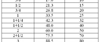
Designers also use tables to calculate basic parameters.
Table of main parameters of area and shape of sections
Calculation of the area of an oval duct
The diameters of an oval duct are calculated based on its area. The following formulas are used:
Diameter:
P – perimeter of the ovaloid circle,
The area of the oval duct is calculated by the formula:
a, b – large and small diameter of the oval, respectively.
Oval air channels combine the advantages of rectangular and round ones
Purpose of performing calculations
Features of the calculation and selection of air ducts depend on their type and the material from which they are made. The latter characteristic determines the nuances that arise during air movement and the peculiarities of the interaction of an air avalanche with the walls.
Air ducts are:
- metal - it can be black steel, galvanized, stainless steel;
- aluminum flexible corrugated;
- plastic ventilation ducts - flexible and rigid;
- fabric.
According to the cross-section geometry, air ducts are made round, rectangular, or oval. The latter are not as popular as the first two.
Even if there is the most correct design of the ventilation system, an error in the selection of air duct sections can lead to disruption of air circulation.
The consequence of errors in calculations will be increased humidity, and then mold and mildew in the room. Without correct calculation of the area of all parts, it is impossible to select suitable elements of the ventilation complex
This parameter depends on:
- the speed of flow of the air mass and its volume;
- degree of tightness of connections;
- noisy ventilation system;
- power consumption
Calculations done correctly will make it possible to save money, since the amount of material will be determined accurately. But besides economic issues, the main thing is the ventilation parameters, which ensure comfortable living conditions for people.
Algorithm for calculating the cross-section of air ducts
Calculation of the cross-section of air ducts involves determining the size of the air ducts depending on the flow rate of the air passed through. It is performed in 4 stages:
- Conversion of air flow to m3/s
- Choosing air speed in the duct
- Determining the cross-sectional area of the duct
- Determining the diameter of a round or width and height of a rectangular duct.
At the first stage of air duct calculation, the air flow rate G, usually expressed in m3/hour, is converted to m3/s. To do this, you need to divide it by 3600:
- G [m3/s] = G [m3/hour] / 3600
At the second stage, you should set the speed of air movement in the duct. The speed should be specified, not calculated. That is, choose the air speed that seems optimal.
The high air velocity in the duct allows the use of small cross-section ducts. However, the air flow will be noisy, and the aerodynamic resistance of the air duct will greatly increase.
Low air speed in the air duct ensures quiet operation of the ventilation system and low aerodynamic resistance, but makes the air ducts very bulky.
For general ventilation systems, the optimal air speed in the air duct is considered to be 4 m/s. For large air ducts (600x600 mm or more), the air speed can be increased to 6 m/s. In smoke removal systems, air speed can reach or exceed 10 m/s.
So, at the second stage of calculating air ducts, the air speed v [m/s] is set.
At the third stage, the required cross-sectional area of the air duct is determined by dividing the air flow by its speed:
- S [m2] = G [m3/s] / v [m/s]
At the fourth , final stage, its diameter or the lengths of the sides of a rectangular section are selected for the resulting cross-sectional area of the air duct.
The importance of correct section definition
The ventilation system is represented by a network of channels of one or another cross-section through which air flows pass. Additionally, various adapters, shut-off valves, filters, and devices for forced air circulation can be installed. But the former are the basic basis, since the choice of components depends on:
- the volume of passing flow for a specific period of time;
- efficiency of air renewal in the serviced premises;
- tightness of the entire structure;
- noise level as air masses flow in the operating mode of the network;
- degree of energy consumption of devices built into the circuits.
Engineering calculations of the area of air ducts and fittings are influenced by several important points:
- Object type . The choice of components must be made taking into account the number of premises served and the sanitary requirements for specific premises. For example, the office and the kitchen require different volumes of fresh air over an identical period of time. Attention is also drawn to the area or cubic capacity of the object, the constant number of people who live or are inside the building. Here, according to SanPiN standards, it is customary to take into account 60 cubic meters per person. For a temporary stay – 20 cubic meters.
An example of the distribution of premises in a one-story house Source yandex.net
- Conditions for installation . In cross-section, channels ready for installation can be round, oval, square and rectangular. Some properties have low ceilings and need flat air ducts, while others can rely on design. The second option involves the use of any samples, including combination.
- Air duct material . Based on their design, you can find steel (in various treatments), aluminum (in the form of flexible corrugation), plastic with different hardness and fabric ventilation ducts on trading floors. Here the criterion is considered from the point of view of friction forces, resistance between the walls and the air mass. There are also differences in appearance and noise levels during system operation.
When calculating the cross-section of air ducts, it is important to take into account all the nuances. Any error can lead to malfunction of the system as a whole and to a decrease in ventilation efficiency. That is, air purification in a particular room will occur fully, and the humidity level will be increased. The latter often leads to the formation of areas affected by mold, fungi and bacteria.
Formation of condensation on top of the ventilation circuit Source propodval.ru
Example of air duct calculation
As an example, let's calculate the cross-section of an air duct with an air flow of 1000 m3/hour:
- G = 1000/3600 = 0.28 m3/s
- v = 4 m/s
- S = 0.28 / 4 = 0.07 m2
- In the case of a round duct, its diameter would be D = root (4·S/ π) ≈ 0.3 m = 300 mm. The nearest standard duct diameter is 315 mm.
In the case of a rectangular duct, it is necessary to select A and B such that their product is approximately 0.07. It is recommended that A and B do not differ from each other by more than three times, that is, a 700x100 air duct is not the best option. Better options: 300x250, 350x200.
Differences between kitchen hood and ventilation
Ventilation in the house ensures natural air exchange and air circulation in all rooms. It is designed for a standard low level of air pollution and cannot fully clean the kitchen from smoke, steam and strong odors.
A hood with an air duct is an additional air cleaning system, usually of a forced type. It is productive and can remove large amounts of smoky and polluted air, as well as eliminate most strong kitchen odors.
That is, the hood is the second level of ventilation, which is guaranteed to provide the required sanitary conditions and clean air in your kitchen under any load.
Calculation of the area of air ducts and fittings
Straight duct section
Circular duct area
| Diameter Length d | 100125160200250280315355400450500560630710800900100011201250140016001800200022402500 | mm | |
| L | m |
| m2 |
Rectangular duct area
| Width Height Length a | 5010015020025030035040045050055060065070075080085090095010001100120013001400150016001700180019002000 | mm | |
| b | 5010015020025030035040045050055060065070075080085090095010001100120013001400150016001700180019002000 | mm | |
| L | m |
| m2 |
Branch
S
Circular outlet area
| |||||
| Square | |||||
| m2 |
| 5010015020025030035040045050055060065070075080085090095010001100120013001400150016001700180019002000 | mm | |
| b | 5010015020025030035040045050055060065070075080085090095010001100120013001400150016001700180019002000 | mm |
| α | 1530456090 | ° |
| m2 |
Transition
| Circular transition area | 100125160200250280315355400450500560630710800900100011201250140016001800200022402500 | mm |
| D2 | 100125160200250280315355400450500560630710800900100011201250140016001800200022402500 | mm |
| L | mm |
| 5010015020025030035040045050055060065070075080085090095010001100120013001400150016001700180019002000 | mm | |
| b | 5010015020025030035040045050055060065070075080085090095010001100120013001400150016001700180019002000 | mm |
| D | 100125160200250280315355400450500560630710800900100011201250140016001800200022402500 | mm |
| L | mm |
| Width Height Width Height Length A | 5010015020025030035040045050055060065070075080085090095010001100120013001400150016001700180019002000 | mm |
| B | 5010015020025030035040045050055060065070075080085090095010001100120013001400150016001700180019002000 | mm |
| a | 5010015020025030035040045050055060065070075080085090095010001100120013001400150016001700180019002000 | mm |
| b | 5010015020025030035040045050055060065070075080085090095010001100120013001400150016001700180019002000 | mm |
| L | mm |
| m2 |
Tee
| Circular tee area | 100125160200250280315355400450500560630710800900100011201250140016001800200022402500 | mm |
| L | mm | |
| D2 | 100125160200250280315355400450500560630710800900100011201250140016001800200022402500 | mm |
| l | mm |
| 100125160200250280315355400450500560630710800900100011201250140016001800200022402500 | mm | |
| L | mm | |
| a | 5010015020025030035040045050055060065070075080085090095010001100120013001400150016001700180019002000 | mm |
| b | 5010015020025030035040045050055060065070075080085090095010001100120013001400150016001700180019002000 | mm |
| l | mm |
| mm | ||
| b | 5010015020025030035040045050055060065070075080085090095010001100120013001400150016001700180019002000 | mm |
| L | mm | |
| d | 100125160200250280315355400450500560630710800900100011201250140016001800200022402500 | mm |
| l | mm |
| 5010015020025030035040045050055060065070075080085090095010001100120013001400150016001700180019002000 | mm | |
| B | 5010015020025030035040045050055060065070075080085090095010001100120013001400150016001700180019002000 | mm |
| L | mm | |
| a | 5010015020025030035040045050055060065070075080085090095010001100120013001400150016001700180019002000 | mm |
| b | 5010015020025030035040045050055060065070075080085090095010001100120013001400150016001700180019002000 | mm |
| l | mm |
Stub
| Round plug area | 100125160200250280315355400450500560630710800900100011201250140016001800200022402500 | mm |
| 5010015020025030035040045050055060065070075080085090095010001100120013001400150016001700180019002000 | mm | |
| b | 5010015020025030035040045050055060065070075080085090095010001100120013001400150016001700180019002000 | mm |
Rectangular duck
| Weft area with offset in 1st plane | 5010015020025030035040045050055060065070075080085090095010001100120013001400150016001700180019002000 | mm |
| b | 5010015020025030035040045050055060065070075080085090095010001100120013001400150016001700180019002000 | mm |
| l | mm | |
| h | mm |
| 5010015020025030035040045050055060065070075080085090095010001100120013001400150016001700180019002000 | mm | |
| b | 5010015020025030035040045050055060065070075080085090095010001100120013001400150016001700180019002000 | mm |
| l | mm | |
| h1 | mm | |
| h2 | mm |
Umbrellas
| Island type umbrella area | 5010015020025030035040045050055060065070075080085090095010001100120013001400150016001700180019002000 | mm |
| B | 5010015020025030035040045050055060065070075080085090095010001100120013001400150016001700180019002000 | mm |
| a | 5010015020025030035040045050055060065070075080085090095010001100120013001400150016001700180019002000 | mm |
| b | 5010015020025030035040045050055060065070075080085090095010001100120013001400150016001700180019002000 | mm |
| h | mm |
| 5010015020025030035040045050055060065070075080085090095010001100120013001400150016001700180019002000 | mm | |
| b | 5010015020025030035040045050055060065070075080085090095010001100120013001400150016001700180019002000 | mm |
| h | mm | |
| c | 5010015020025030035040045050055060065070075080085090095010001100120013001400150016001700180019002000 | mm |
Calculation of the area of duct fittings
It will be difficult for a person not familiar with mathematical formulas to perform calculations correctly; an error in one indicator will affect the operational characteristics of the ventilation system, and accordingly, the quality of air purification.
To simplify the process of calculating the surface area of the air duct, you can use an online calculator and special programs that perform all the algorithms; for this you only need to enter the primary indicators.
Program for counting and selecting elements
What programs exist for finding the parameters of duct fittings?
To help engineering workers eliminate errors associated with the human factor, as well as to speed up the process, special programs have been created, with the help of which you can not only perform competent calculations, but also 3D modeling of the future structure.
| Program | Short description |
| Vent-Calc | The program calculates the cross-sectional area, thrust, resistance on different segments. |
| GIDRV 3.093 | The program will perform a new and control calculation of the air duct data. |
| Ducter 2.5 | In the program you can select the elements of the ventilation system and calculate the cross-sectional areas of the structure. |
| CADvent | This complex is created on the basis of AutoCAD and has the most detailed library of elements and capabilities. |
Software calculation and design of ventilation
Video description
This video details the equivalent duct diameter:
Review of other techniques
In the accompanying documentation or specialized regulatory literature you can find graphic nonograms. There are several axes on which a scale is indicated for pressure, speed, air exchange and the cross-section of the ventilation duct. Knowing the first indicators, you can compare them and, at the intersection, consider the desired option for the contour size. The value will be approximate, but it can be guided by taking into account the minimum noise level.
Engineers and designers use special programs to calculate the quadrature of the air duct. There are cumbersome tables that take into account the maximum number of nuances. They are related both to the type of kit selected for installing a ventilation system, and to the characteristics of the room being served or the facility as a whole.
Specialized program for engineering calculations of ventilation Source odstroy.ru
An alternative to specialized programs is an online calculator. This approach allows you to determine the required standard sizes of ventilation ducts and shaped products with approximate accuracy. But taking into account the standardized parameters of the offered assortment on trading platforms, such results can be applied to drawing up a project for the private sector.
Calculation of square meters (sectional area) of the air duct
The size of the ventilation pipe is influenced by many factors: flow speed, pressure on the walls, air volume. If you make calculations with an error, for example, reduce the cross-section of the main network, the speed of air masses will increase, noise will appear, pressure and electricity consumption will increase.
The calculation of the cross-sectional area of the duct is calculated using the following formula:
S = L × κ / ω , where:
- L – air flow, m³/h;
- ω – speed of air flow, m/s;
- κ – calculated coefficient equal to 2.778.
Air performance
The calculation of the ventilation system begins with determining the air productivity (air exchange), measured in cubic meters per hour. For calculations, we will need a site plan, which indicates the names (purposes) and areas of all premises.
It is necessary to supply fresh air only to those rooms where people can stay for a long time: bedrooms, living rooms, offices, etc. Air is not supplied to the corridors, but is removed from the kitchen and bathrooms through exhaust ducts. Thus, the air flow pattern will look like this: fresh air is supplied to the living quarters, from there it (already partially polluted) enters the corridor, from the corridor into the bathrooms and the kitchen, from where it is removed through exhaust ventilation, taking with it unpleasant odors and pollutants. This air movement pattern provides air support for “dirty” rooms, eliminating the possibility of unpleasant odors spreading throughout the apartment or cottage.
For each living space, the amount of air supplied is determined. The calculation is usually carried out in accordance with SNiP 41-01-2003 and MGSN 3.01.01. Since SNiP sets more stringent requirements, we will be guided by this document in our calculations. It states that for residential premises without natural ventilation (that is, where windows do not open), the air flow must be at least 60 m³/h per person. For bedrooms, a lower value is sometimes used - 30 m³/h per person, since in a state of sleep a person consumes less oxygen (this is permissible according to MGSN, as well as according to SNiP for rooms with natural ventilation). The calculation takes into account only people staying in the room for a long time. For example, if a large company gathers in your living room a couple of times a year, then there is no need to increase the ventilation performance because of them. If you want your guests to feel comfortable, you can install a VAV system that allows you to regulate the air flow separately in each room. With such a system, you can increase air exchange in the living room by reducing it in the bedroom and other rooms.
After calculating the air exchange for people, we need to calculate the air exchange by frequency (this parameter shows how many times a complete change of air occurs in the room within one hour). To ensure that the air in the room does not stagnate, it is necessary to ensure at least one air exchange.
Thus, to determine the required air flow, we need to calculate two air exchange values: by the number of people
and by
multiplicity
and, then select
the larger
of these two values:
- Calculation of air exchange by number of people:
- typical value (according to SNiP) - 60 m³/h;
- Calculation of air exchange by frequency:
L=n*S*H, Where
L
— required supply ventilation capacity, m³/h;
n
— normalized air exchange rate:
for residential premises - from 1 to 2, for offices - from 2 to 3;
S
— room area, m²;
H
— room height, m;
L = N * Lnorm
, Where
L
— required supply ventilation capacity, m³/h;
N
- number of people;
Lnorm
— air consumption rate per person:
- at rest (sleep) - 30 m³/h;
By calculating the required air exchange for each room served and adding the resulting values, we find out the overall performance of the ventilation system. For reference, typical performance values of ventilation systems:
- For individual rooms and apartments - from 100 to 500 m³/h;
- For cottages - from 500 to 2000 m³/h;
- For offices - from 1000 to 10000 m³/h.
Calculation of equivalent diameter of air ducts
The equivalent diameter of a rectangular duct is calculated by the formula:
- Deq_pr = 2 A B / (A + B), where A and B are the width and height of the rectangular air duct.
For example, the equivalent diameter of a 500×300 duct is 2·500·300 / (500+300) = 375 mm. This means that a 375mm round duct will have the same aerodynamic drag as a 500x300mm rectangular duct.
The equivalent diameter of a square duct is equal to the side of the square:
- Deq_q = 2 A A / (A+A) = A.
And this fact is very interesting, because usually the larger the cross-sectional area of the air duct, the lower its resistance. However, the round shape of the air duct section has the best aerodynamic performance. That is why the resistance of square and round ducts are equal, although the cross-sectional area of a square duct is 27% larger than the cross-sectional area of a round duct.
In general, the formula for the equivalent duct diameter is as follows:
- Deq = 4·S / P, where S and P are the area and perimeter of the air duct, respectively.
Using this formula, you can confirm the correctness of the above formulas for rectangular and square ducts, and also ensure that the equivalent diameter of a round duct is equal to the diameter of this duct:
- Dround = 4·π·R2 / 2·π·R = 2R = D.
In addition, a table of equivalent duct diameters
General information for calculation
The diameter of the ventilation pipes depends on the area of the house and the number of people living.
Key indicators include the cross-sectional area of the duct, which determines the speed of movement of flows. The pattern is that as the dimensions increase, the pressure decreases and vice versa. The calculation of the quadrature of air ducts is carried out in several ways in order to be able to compare the results.
Indicators for choosing pipes can be calculated using the following values:
- in accordance with hygienic and sanitary standards given in SanPiN;
- by the number of people in the room;
- by area and volume of the room.
The calculation is carried out for a separate room or the building as a whole. The amount of material is determined based on the configuration and dimensions of the system. Round pipes require a diameter and total length, while rectangular pipes are calculated using the width, height and length of the line.
The surface area of shaped parts of air ducts is determined taking into account bends, adapters of various shapes, their width, angle of rotation and height are taken into account.
Calculation of materials for air ducts and fittings
Having the area of straight sections, the number and type of shaped products, we can easily determine the volume of material that will be used in their manufacture. For example, to manufacture a section of a circular duct with a diameter of 100 mm and a length of 1 m, 0.314 m² of sheet metal will be needed.
This can be easily calculated using the formula:
π × D (100 mm = 0.1 m) × L (1 m) = 3.14 × 0.1 × 1 = 0.314 m².
The amount of material for straight sections of rectangular air ducts is calculated in a similar way.
There are no specific formulas for calculating shaped products. More precisely, they exist: for each part of a shaped product of a certain shape there is a separate formula. But calculating them manually is impractical. As a rule, the required amount of material is calculated empirically after making cutting patterns.
The process of creating a circular air duct by winding a steel spiral tape
Specifications and Dimensions
PVC-based air ducts are made of special ABS plastic. A sag of 4% is acceptable in relation to it. Other positive characteristics include:
- no need for additional thermal insulation of the roof;
- availability of self-regulation;
- low probability of corrosion;
- smooth inner surface, due to which there is no possibility of static resistance when air passes through;
- reduced noise and air losses;
- service life - 20 years or more.
Plastic is not fire resistant, so placing it near the chimney is not recommended. If increased fire protection is required, preference should be given to galvanized products. As for sizes, the following features stand out:
- Most often, buyers purchase round air ducts with a diameter of 1, 1.25, 1.5 cm. In accordance with GOST, their cross-section should be 200 cm.
- The rectangular plastic air duct has standard dimensions of 55 by 110, 60 by 120 and 50 by 204 mm.
- The length of flexible air ducts is 20 m.
The kitchen hood contains elements that are most often made of plastic. Experts strongly recommend installing plastic on exhaust ventilation ducts. There are no restrictions here. But the influx requires products made from a special type of plastic that can withstand thermal effects. This is especially true if there is recovery or heating.
When choosing plastic air ducts, you need to look at the characteristics of a particular room. Sometimes, due to potential problems with the fire service, their use is not recommended. This is true, for example, if the ventilation is made of plastic. You should also be careful with a frame house.
An example of calculating the equivalent diameter of air ducts and some conclusions
As an example, let's determine the equivalent diameter of the duct 600×300:
Deq_600_300 = 2 600 300 / (600+300) = 400 mm.
It is interesting to note that the cross-sectional area of a round duct with a diameter of 400 mm is 0.126 m2, and the cross-sectional area of a 600x300 duct is 0.18 m2, which is 42% more. The steel consumption per 1 meter of a round air duct with a cross-section of 400 mm is 1.25 m2, and for 1 meter of an air duct with a cross-section of 600×300 - 1.8 m2, which is 44% more.
Thus, any rectangular air duct similar to a round one is significantly inferior to it both in compactness and in metal consumption.
Let's consider another example - let's determine the equivalent diameter of the air duct 500×100 mm:
Deq_500_100 = 2·500·100 / (500+100) = 167 mm.
Here the difference in cross-sectional area and metal consumption reaches 2.5 times. Thus, the equivalent diameter formula for a rectangular duct explains the fact that the more “flattened” the duct is (the greater the difference between the values of A and B), the less efficient this duct is from an aerodynamic point of view.
This is one of the reasons why it is not recommended to use air ducts in ventilation technology, in the cross-section of which one side is more than three times larger than the other.
Selecting an air handling unit
To select an air handling unit, we will need the values of three parameters: overall performance, heater power and air network resistance. We have already calculated the performance and power of the heater. The network resistance can be found using the Calculator or, for manual calculation, taken equal to the typical value (see section Calculation of network resistance).
To select a suitable model, we need to select ventilation units whose maximum performance is slightly greater than the calculated value. After this, using the ventilation characteristic, we determine the system performance at a given network resistance. If the obtained value is slightly higher than the required performance of the ventilation system, then the selected model is suitable for us.
As an example, let’s check whether a ventilation unit with the ventilation characteristics shown in the figure is suitable for a cottage with an area of 200 m².
The estimated productivity is 450 m³/h. Let us take the network resistance to be 120 Pa. To determine the actual performance, we must draw a horizontal line from the value of 120 Pa, and then draw a vertical line down from the point of its intersection with the graph. The intersection point of this line with the “Performance” axis will give us the desired value - about 480 m³/h, which is slightly more than the calculated value. So this model suits us.
Note that many modern fans have flat ventilation characteristics. This means that possible errors in determining the network resistance have almost no effect on the actual performance of the ventilation system. If in our example we had made a mistake in determining the resistance of the air supply network by 50 Pa (that is, the actual network resistance would not have been 120, but 180 Pa), the system performance would have dropped by only 20 m³/h to 460 m³/h, which had no effect would be the result of our choice.
After choosing an air handling unit (or a fan, if a dial system is used), it may turn out that its actual performance is noticeably higher than the calculated one, and the previous model of the air handling unit is not suitable because its performance is not enough. In this case we have several options:
- Leave everything as is, but the actual ventilation performance will be higher than the calculated one. This will lead to increased energy consumption spent on heating the air during the cold season.
- “Strangle” the ventilation unit using balancing throttle valves, closing them until the air flow in each room drops to the calculated level. This will also lead to excessive energy consumption (although not as much as in the first option), since the fan will work with excess load, overcoming the increased network resistance.
- Do not turn on maximum speed. This will help if the ventilation unit has 5–8 fan speeds (or smooth speed control). However, most budget ventilation units have only 3-step speed control, which most likely will not allow you to accurately select the desired performance.
- Reduce the maximum productivity of the air handling unit exactly to a specified level. This is possible if the automatic ventilation unit allows you to adjust the maximum fan rotation speed.
Calculation of heating power in the network
The temperature of the air entering the premises is strictly regulated. For example, for residential buildings the minimum value is +18°C. To calculate the power of the heating equipment used, it is necessary to find out from the standards the minimum temperature value of the climatic zone where the building is located. The difference between these temperatures is the main factor in determining the power of the heating device. At the same time, it is not at all necessary to use the most powerful heater capable of heating the room at a minimum external temperature. If the ventilation has a performance control system, then during maximum load on the heater the air supply intensity is simply reduced.
The power of the heating device is calculated using the formula:
P — design power of the heating device (recuperator or heater), (kW);
Δt — difference in air temperature at the entrance to the ventilation system and at the supply to the room, (°C);
Q — ventilation system performance, (m³/h);
τv is the volumetric heat capacity of air, depends on the totality of the values of humidity, temperature and pressure, but is taken as a coefficient of 0.336 W × (h/m³/°C).
Examples of using air ducts as a decorative element of premises
Rules for using measuring devices
When measuring air flow speed and its consumption in a ventilation and air conditioning system, you need to correctly select devices and comply with the following rules for their operation.
This will allow you to obtain accurate results of air duct calculations, as well as create an objective picture of the ventilation system.
Observe the temperature regime indicated in the device passport. Also monitor the position of the probe sensor. It must always be oriented exactly towards the air flow.
If this rule is not followed, the measurement results will be distorted. The greater the deviation of the sensor from the ideal position, the higher the error will be.
Calculation of air speed in the duct
When calculating a ventilation system, one of the main indicators is the air exchange rate. In other words, how much air mass is needed to comfortably ventilate 1 m³ of a room in 1 hour. In this case, you can also refer to the development tables, but you should know that all the indicators in them are rounded, so more accurate data is obtained by doing your own calculations. The air exchange rate can be calculated using the formula:
N = V / W , where
- V – the amount of fresh air masses that enter the room in 60 minutes (m³/hour);
- W – room volume, m³.
You should know this! A comfortable air exchange rate for most domestic ventilation systems is 3-4 m/s.
You can carry out aerodynamic calculations and calculate the speed of air movement using the following formula:
ω = L / 3600 × S , where
- L – volume of air used per 1 hour;
- S – cross-sectional area of the air duct.
Air exchange standards for an apartment
Calculation steps
Calculation work consists of several stages:
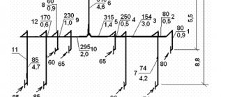
- Drawing up a general diagram of the ventilation system. Here the lengths of straight sections, rotating parts and their type, and places where the section changes should be noted.
- Selecting an air exchange rate identical to sanitary and hygienic requirements.
- Calculation of the speed of movement of air masses through the pipeline. This parameter depends on the type of ventilation, and it can be natural or forced.
- Calculation of air duct area and other parameters.
There are many programs for performing such calculations.
Calculating formulas for a complex system is not an easy task. For a small house, calculating the area of individual elements and the cross-section of air ducts is quite possible
Calculation of duct cross-section
The expression used to calculate the quadrature of shaped elements and air ducts looks like this:
Sc = (L x 2.778) : V,
Where:
- Sc —area in cross section;
- L is the flow rate of air circulating in the system;
- 2.778 — coefficient that reconciles different dimensions;
- V is the speed of an air avalanche in a specific location, measured in meters per second.
The result of the calculation will be a value measured in cm².
There is an alternative formula:
S = L : k × V,
The K coefficient in this case is 3600.
Determining the actual duct area
The regular ventilation area for round ventilation ducts is calculated using the formula:
S = (π x D2) : 400,
Where:
- S —actual area;
- D —diameter.
For rectangular pipelines:
S = (A x B) : 100,
Where:
- S —actual area;
- D —diameter;
- A is the height of the air duct;
- B is the width of the structure.
The cross-sectional area for a pipe with an oval cross-section is calculated using the formula:
S = π × A × B: 4,
Where:
- A - larger diameter of the oval;
- B is the smaller diameter, respectively.
There are other formulas for calculating the area of the air duct.
Using a regulatory document such as SNiP, you can compare the cross-sectional dimensions of air ducts with the required indicators. This makes it even easier to determine the appropriate size of the air piping.
Some manufacturers provide nomograms in the description of air ducts. They are also in the normative literature.
Nomogram for a metal air duct with a circular cross-section. The values from it are substituted into the formula. All flexible air ducts are supplemented with such schemes (+)
From the nomograms you can take the value of the cross-sectional area. It is approximate, but suitable for creating a system with minimal noise.
To find the duct dimensions for a specific branch pipe that transports a given volume of air, you need to do the following:
- Determine on the nomogram the point of intersection of the volume of air moved in 1 hour and the line of highest speed for the design section.
- Near this point, find the value of the most suitable diameter.
In addition, having a nomogram, you can not only facilitate the calculation of the cross-section of air ducts and fittings, but also specify the pressure loss along a section of the air line at a set speed.
It is not necessary to use a nomogram; you can determine the required cross-sectional area depending on the speed of the air mass.
Air speed calculation
Using formulas or special tables, calculate the air duct speed. The key parameter here is the multiplicity index, which determines the volume of air at which a room with a volume of 1 m3 is fully ventilated within 1 hour.
To determine the multiplicity index, experts recommend studying specific conditions at existing industrial facilities for which there is actual data on the release of gases, toxic vapors, etc. It is best to do an independent calculation using formulas.
To simplify calculations, there are special tables from which you can take the ready-made value of the multiplicity indicator, but you need to keep in mind that they contain rounded parameters
The formula for calculating the multiplicity looks like this:
N=V:W,
Where:
- N is the required multiplicity;
- V is the volume of fresh air mass entering the room within an hour;
- W is the volume of the room.
The unit of multiplicity is the number of times/hour, V is measured in mᶾ/h, volume is in mᶾ.
Let's consider a specific example of determining the required amount of air by multiplicity.
There is a living room with a volume of 22 mᶾ. It will require air: L = 22 x 6 = 132 m3, here 6 is the air exchange rate taken from the table.
The speed of mass movement (V) is measured in m/s and determined by the formula:
V=L : 3600 x S,
Where:
- L —air used (mᶾ/h);
- S is the cross-sectional area of the air duct (mᶾ).
Additionally, 2 more parameters affect the speed of air movement: noise level, vibration coefficient. They must be taken into account when designing the system.
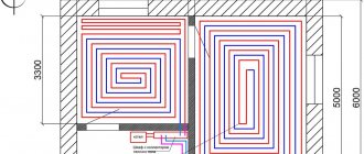
Calculation example for a small cottage
For the calculation, we took a cottage with an internal area of 108.8 m2 and a height from floor to ceiling of 3 m. Inside there is a living room, bedroom, children's room, kitchen, and bathroom. The multiplicity indicator is taken equal to 1.
The ventilation system allows you to rid the room of impurities that are harmful to health - potentially dangerous and provoking allergic reactions, worsening well-being
First, calculate the amount of removed and incoming air for the entire building.
The SNiP method is used for this:
- Since the bedroom and living room are the same in area, the amount of air removed from them is 21 x 3 x 1 = 63 mᶾ/h.
- For a child’s room - 24 x 3 x 1 = 72 mᶾ/h.
- For the kitchen - 22 x 3 x 1 + 100 = 166 mᶾ/h.
- For a bathroom - 10 x 3 x 1 = 30 mᶾ/h.
- As a result: 63 x 2 + 48 + 166 + 30 = 394 mᶾ/h.
The corridor and hallway were not taken into account. 100 mᶾ is the volume that goes through the hood in the kitchen.
Correct distribution of air flow in the house is also a very important point. In buildings of this type, a natural ventilation system is usually installed. There is still a forced element here - a kitchen hood.
Next, determine the diameters of the ventilation ducts. Since 100 m3 is removed forcibly by the hood, it remains to distribute the remaining 294 m3. They will leave naturally through 2 shafts. For each it will be necessary: 294: 2 = 147 mᶾ.
Since air speed in natural ventilation shafts ranges from 0.5 to 1.5 m/s, the average value of 1 m/s is usually taken in calculations. Substituting the known values into the formula S = L: k × V, they find: S = 147: 3600 x 1 = 0.0408 m².
Now it is possible to determine the diameter of an air duct with a circle in cross-section using the formula: S = (π x D2) : 400 or 0.0408 = (3.14 x D2) : 400.
Having solved this equation with one unknown, through simple calculations, they find that the diameter of the air duct is 2.28 mm. The nearest larger standard pipe size is selected for this value.
Using this conversion table, you can select the equivalent diameter of a circular duct. This greatly simplifies the calculation
When installing a rectangular air duct, select its size according to the table, focusing on the area. The nearest larger value is 200 x 250 mm.
Using the same scheme, the cross-sectional area of the outlet for the kitchen hood is determined, with the difference that the air speed here is 3 m/s. S = 100: 3600 x 3 = 0.083 m² or diameter 107 mm.
A conversion table is needed when you need to calculate air ducts with a rectangular cross-section and apply the table for round products. Here are the diameters of air ducts with a circular cross-section, in which the pressure reduction due to friction is equal to the same value in a rectangular design.
There are three ways to determine the equivalent value:
- by speed;
- along the cross section;
- by consumption.
These values are associated with different parameters of the air duct. Each of them has an individual method of using tables. The main thing is that, regardless of the technique used, the amount of pressure loss due to friction is the same.
Finally, the speed is checked: V = 147: (3600 x 0.0408) = 1.0 m/s. This is within the acceptable limit.
Shaped products and their calculation
When installing air ducts, straight sections of various sizes are connected using shaped products.
When producing both air ducts and fittings, it is necessary to calculate their area. Without this, it is impossible to determine the correct amount of material required for the manufacture of parts.
Shaped products include:
- Bends . They are used to change the direction of the air pipeline at any angle. They come in both round, rectangular and oval.
- Transitions . They are used to connect air ducts of different sections. Any geometry - from round to combined.
- Couplings, nipples . Connect straight sections of the highway.
- Tees . The branches or two branches of the air duct are connected.
- Stubs . Blocking the air flow.
- Crosses . Separate or connect air flows.
- Ducks . Provide multi-level transition of the air duct.
To calculate the required parameters of shaped products, mathematical skills are required.
Each shaped product has its own special role in the ventilation system. Manufacturers design each of them separately. They are supplied together with the main elements
An error made in one indicator will lead to a deterioration in the operational characteristics of the system. There are no ready-made formulas for such calculations.
The table shows standard sizes of air ducts. Even professionals use these and similar special tables instead of complex calculations
Many designers use special programs and online calculators. You only need to enter the primary values and get ready-made parameters at the output.
The programs allow you not only to determine the required sizes of all parts, but also to make their development. Such a development, printed on a 3D printer, allows for a perfect fit of the ventilation ducts.
Pressure loss at local resistances
In the air duct network there are places of greatest resistance to air flow: turns, bends, tees, places where the cross-section changes on adapters. Their aerodynamic losses are calculated separately, since each type of shaped product has individual drag coefficients.
Table of local resistance coefficients (KMR) for various shaped products
Formula for pressure loss at each section of local resistance, taking into account the coefficients:
where S is speed, ρ is air density.
Important! The density of air depends on its temperature. For example, at 20°C the air density will be 1.2 kg/m³. This parameter is also taken from tables in relevant regulatory sources.
General formula for pressure loss in shaped products:
Σξ – sum of local resistance parameters.
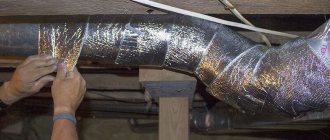
Sound and heat insulation of ventilation ducts
Some useful tips on the correct use of devices
If the air flow in the duct is characterized by an increased level of dust, it is better not to use a hot-wire anemometer and pitot tube. Since the hole in the tube that receives the total flow pressure has a small diameter, it can quickly become clogged when exposed to contaminated air.
Thermal anemometers are not suitable for operation in conditions of high air flow velocities (more than 20 m/s). The fact is that the main temperature sensor, which is characterized by increased sensitivity, can simply collapse under strong air pressure.
The use of control and measuring instruments to determine air flow must be carried out strictly within the nominal temperature ranges specified in the instrument data sheets.
In flue ducts (air ducts in which mainly heated air flows), it is recommended to use pneumometric tubes, the body of which is made of stainless steel. The use of equipment with plastic components in these pipes is undesirable due to possible deformation of the housing under the influence of high temperatures.
When measuring speed and air flow, you must ensure that the sensitive sensor of the probe is always oriented exactly towards the air flow. Failure to comply with this requirement leads to distortion of measurement results. Moreover, the greater the degree of deviation of the sensor from the ideal position, the greater will be the distortions and inaccuracies.
Thus, the correct choice of instrumentation for determining the flow of air masses in the air duct and their proper use during operation will allow specialists to form an objective picture of room ventilation
This aspect is of particular importance when it comes to residential premises.
Formula for calculating the area of air ducts
The area of the air ducts is determined by multiplying the perimeter of the air duct cross-section by the length of the air duct:
- S = П·L, where П and L are, respectively, the perimeter and length of the air duct in meters.
It is important to remember the dimensions of the quantities in the formula above. Typically, the duct cross-section is specified in millimeters (for example, diameter 250 or section 500×250), and the length is specified in meters (for example, 5 meters). But it is necessary to substitute all values expressed in meters into the formula. Moreover, you must first calculate the length of the perimeter of the air duct section.
To simplify the task of calculating the area of air ducts, ready-made formulas for round and rectangular air ducts are used.
Recommended air speed values in the ventilation system, m/s
| Apartments | Offices | Industrial premises | |
| Supply grilles | 2.0-2.5 | 2.0-2.5 | 2.5-6.0 |
| Main air ducts | 3.5-5.0 | 3.5-6.0 | 6.0-11.0 |
| Branches | 3.0-5.0 | 3.0-6.5 | 4.0-9.0 |
| Air filters | 1.2-1.5 | 1.5-1.8 | 1.5-1.8 |
| Heat exchangers | 2.2-2.5 | 2.5-3.0 | 2.5-3.0 |
Vibration level
Vibration is a phenomenon that, along with noise, is always present in air ducts if a forced ventilation circuit is used.
Its value depends on the following factors:
- cross-sectional dimensions of air channels;
- material used to make ventilation pipes;
- composition and quality of gaskets between air duct pipes;
- the speed of air movement in the channels of the ventilation system.
The maximum value of vibration indicators is closely related to the fan power.
Standard indicators that must be taken into account when calculating the parameters of air ducts and choosing the type of ventilation devices are shown in the table:
| Maximum permissible values of local vibration | Maximum permissible values of local vibration | |||
| In vibration acceleration values | In vibration velocity values | |||
| m/s | dB | m/s x 10-2 | dB | |
| 8 | 1.4 | 73 | 2.8 | 115 |
| 16 | 1.4 | 73 | 1.4 | 109 |
| 31.5 | 2.7 | 79 | 1.4 | 109 |
| 63 | 5.4 | 85 | 1.4 | 109 |
| 125 | 10.7 | 91 | 1.4 | 109 |
| 250 | 21.3 | 97 | 1.4 | 109 |
| 500 | 42.5 | 103 | 1.4 | 109 |
| 1000 | 85.0 | 109 | 1.4 | 109 |
| Corrected and equivalently adjusted values and their levels | 2.0 | 76 | 2.0 | 112 |
If the ventilation design is carried out correctly, the air flow speed in the air passages should not affect changes in noise and vibration levels in the system.