To ensure stability in the operation of an autonomous water supply system, it is necessary first of all to correctly calculate the pump power. Let's look at what this parameter is, what are the criteria for choosing a pump, what main characteristics need to be calculated, what factors directly influence the calculation, what is the essence of the calculation method by measurement and calculation, and what are the main features of calculating the parameters of pumps of various types.
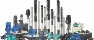
Each type of pump has its own power value and operating features Source cnp-center.ru
Pressure
Pressure (p) expresses the force acting per unit area and is divided into static and dynamic pressure. The sum of these two pressures is the total pressure.
Static pressure is measured using a pressure gauge, exclusively when the liquid is still, or using a pressure tap installed perpendicular to the direction of flow, see Figure 2.3.
To measure total pressure, the pressure tap inlet should be positioned facing the direction of flow, see Figure 2.3. Dynamic pressure is defined as the difference between total and static pressure. This measurement can be made using a pitot tube.
Dynamic pressure depends on the velocity of the fluid. Dynamic pressure can be calculated using the following formula, in which the velocity (V) is obtained by measurement and the density (ρ) of the fluid is known:
Dynamic pressure can be converted to static pressure and vice versa. When flowing in an expanding pipe, dynamic pressure is converted into static pressure, see Figure 2.4. The flow in a pipe is called pipe flow, and the section of the pipe where the diameter of the pipe increases is called the diffuser.
Advantages and disadvantages
Among the advantages the following can be noted:
- Heat is distributed evenly throughout the building , so all rooms have the same temperature. This avoids cases where large rooms are colder than small ones.
- The system can be adjusted.
- Automatic mode , thanks to which the pump operates continuously, or operates in the set mode.
- Functionality. The operating temperature range of the device is from +2ᵒС to +130ᵒС, so the pumps work with both water and ethylene glycol.
- Good pressure. When the system is given normal pressure, all adjacent equipment will work properly.
- Variety. Therefore, the pumps can be used for both small and large rooms.
The disadvantages include:
- The pump itself is inexpensive, but it consumes 40–80 watts of electricity around the clock, which is a considerable expense.
- The operation of the entire system directly depends on the supply of electricity. This problem can be avoided by installing, for example, a diesel generator in advance.
- There are additional costs for the purchase of taps, filters, etc., which actually increases the cost of the pump.
- Installing the device also costs money, but you can save on this if you do it yourself.
Absolute and relative pressure
Pressure can be expressed in two different ways - as absolute or relative pressure. Absolute pressure is measured relative to absolute 0 and thus can only have a positive value. Relative pressure is measured relative to ambient pressure. Positive relative pressure indicates that the pressure is above barometric pressure, and negative relative pressure indicates that the pressure is below barometric pressure.
The definition of absolute and relative magnitude is also known from temperature measurements, where absolute temperature is measured in Kelvin (K) and relative temperature is measured in degrees Celsius (°C). Temperature in Kelvin is always positive and is measured relative to absolute 0. In contrast, temperature in degrees Celsius is measured relative to the freezing point of water (corresponding to 273.15 K), and can therefore be negative.
Barometric pressure is measured as absolute pressure. Barometric pressure varies with weather and altitude. Conversion from relative to absolute pressure is accomplished by adding the existing barometric pressure to the measured relative pressure.
In practice, static pressure is measured using three different types of pressure gauges.
- An absolute pressure gauge, such as a barometer, measures pressure relative to absolute 0.
- A standard pressure gauge measures pressure relative to atmospheric pressure. This type of pressure gauge is most often used.
- A differential pressure gauge measures the pressure difference between two pressure taps independent of barometric pressure.
How to find out the pump flow rate
The calculation formula looks like this: Q=0.86R/TF-TR
Q – pump flow rate in m.cub./h;
R – thermal power in kW;
TF – coolant temperature in degrees Celsius at the system inlet,
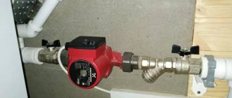
Layout of the heating circulation pump in the system
Three options for calculating thermal power
Difficulties may arise in determining the thermal power index (R), so it is better to focus on generally accepted standards.
Option 1. In European countries it is customary to take into account the following indicators:
- 100 W/sq.m. – for small private houses;
- 70 W/sq.m. – for high-rise buildings;
- 30-50 W/sq.m. – for industrial and well-insulated residential premises.
Option 2. European standards are well suited for regions with mild climates. However, in the northern regions, where there are severe frosts, it is better to focus on the standards of SNiP 2.04.07-86 “Heating networks”, which take into account external temperatures down to -30 degrees Celsius:
- 173-177 W/sq.m. – for small buildings whose number of storeys does not exceed two;
- 97-101 W/sq.m. – for houses of 3-4 floors.
Option 3. Below is a table from which you can independently determine the required thermal power, taking into account the purpose, degree of wear and thermal insulation of the building.
Table: how to determine the required thermal power
Formula and tables for calculating hydraulic resistance
Viscous friction occurs in pipes, shut-off valves and any other components of the heating system, which leads to specific energy losses. This property of systems is called hydraulic resistance. A distinction is made between friction along the length (in pipes) and local hydraulic losses associated with the presence of valves, turns, areas where the diameter of pipes changes, etc. The hydraulic resistance indicator is denoted by the Latin letter “H” and measured in Pa (pascals).
Calculation formula: H=1.3*(R1L1+R2L2+Z1+Z2+….+ZN)/10000
R1, R2 indicate pressure loss (1 – supply, 2 – return) in Pa/m;
L1, L2 – pipeline length (1 – supply, 2 – return) in m;
Z1, Z2, ZN – hydraulic resistance of system components in Pa.
To facilitate calculations of pressure loss (R), you can use a special table that takes into account possible pipe diameters and provides additional information.
Table for determining pressure loss
Averaged data for system elements
The hydraulic resistance of each element of the heating system is given in the technical documentation. Ideally, you should use the specifications specified by the manufacturers. In the absence of product passports, you can rely on approximate data:
- boilers – 1-5 kPa;
- radiators – 0.5 kPa;
- valves – 5-10 kPa;
- mixers – 2-4 kPa;
- heat meters – 15-20 kPa;
- check valves – 5-10 kPa;
- control valves – 10-20 kPa.
Information about the hydraulic resistance of pipes made of various materials can be calculated from the table below.
Pipe pressure loss table
Pressure
The following pages present the various specifications.
The QH curve shows head (H) as a function of flow (Q). Flow (Q) is the volume of fluid passing through the pump per unit time. Flow is usually expressed in cubic meters per hour (m3/h), but formulas use cubic meters per second (m3/s). A typical QH curve is shown in Figure 2.5.
The QH curve for a given pump is constructed using the setup shown in Figure 2.6.
The pump starts and runs at a constant speed. When the valve is completely closed, Q is zero and H reaches its maximum value. As the valve is gradually opened, Q increases and H decreases. H is the height of the liquid column in the open pipe behind the pump. The QH curve is a sequence of points corresponding to pairs of Q and H values, see Figure 2.5.
In most cases, the pump pressure Dptot is measured, and the pressure H is calculated using the following formula:
The QH curve will be exactly the same if the experiment depicted in Figure 2.6 is carried out with a liquid whose density differs from the density of water. Thus, the QH curve is independent of the pumped liquid. This can be explained using theory, where it has been proven that Q and H depend on the geometry of the pump and the speed of rotation of the impeller, but not on the density of the pumped liquid.
The pressure rise in the pump can be measured in meters of water column (mH2O). The water meter is a unit of pressure and should not be confused with head, expressed in meters. As can be seen from the table of physical properties of water, with increasing temperature the density of water changes significantly. Thus, it is necessary to convert pressure to head.
Pump power - what is it, criteria for choosing a pump, design parameters
Pump power refers to the amount of water pumped per unit of time. The value is expressed in liters or cubic meters. m per second and characterizes the performance or useful power of the equipment. In addition to this, there is power consumption. This is an indicator of consumed electricity, expressed in kW. The ratio of useful power to expended power reflects the efficiency factor. The higher its value, the less energy is lost for pumping water, and the more efficient the equipment is, accordingly.
When choosing a pump, the following series of criteria are primarily taken into account:
- Design and technical features.
Specific application conditions always require a pump of a certain design and specified technical parameters, the calculation of which can be performed in advance. In many cases, the choice of equipment is determined by the liquid supply technology. For example, if you need the most uniform pumping of water, then centrifugal models are used.
When the most uniform water supply is required, a centrifugal pump is used Source vseinstrumenti.ru
In other cases, or when technology also requires it, it is allowed to use piston units - providing water supply in portions. Another example of technical requirements is the case when the pump must or is forced to be located inside the source under the water surface. In this case, submersible models are used.
- Type of pumped liquid.
Pumping equipment must ensure unhindered pumping of a specific liquid medium. In private households, pumps are used not only to supply water from a well or well to the home water supply system.
Often, the owners of their home have to pump out cesspools and septic tanks, as well as pump out basements, plinths, and low-lying areas on the site during flooding. In addition, owners of swimming pools and artificial ponds also require a special pumping device. All these liquids can contain both small and large particles, and differ in viscosity and fluidity characteristics from ordinary clean water.
To pump out water with a large amount of impurities, a special type of pump is used Source jeelex-pumps.ru
- Main performance characteristics.
The main parameters of pumping equipment that affect its operation include:
- Performance.
- Pressure
- Power consumption.
To ensure long-term and reliable operation, the first 2 characteristics are taken into account first. As a rule, they depend on each other and determine the scope of application of the equipment. For example, a 1-stage centrifugal pump is capable of moving water up to 100 m, and according to calculations it will have a capacity of up to 1000 m³ per hour. At the same time, multi-stage models are capable of creating a head of up to 1000 m and a useful power of up to 10 thousand cubic meters. meters per hour.
Main design parameters
There are 3 main parameters that most accurately characterize the operation of pumps, these are:
- Performance.
The value is defined as the volume of pumped liquid in a certain period of time, for example, 1 liter per second. In practice, for example, in the water supply system of a private house, it should be equal to the total flow rate from all consumers - shower, sinks, bathtubs, etc.
The pump performance must be such as to satisfy all consumers in the house Source sovet-ingenera.com
However, the theoretical calculation does not take into account possible losses in the form of leaks due to the imperfection of the pipeline. Therefore, there is such a thing as actual consumption. Both quantities are related to each other by volumetric efficiency. It is necessary to take into account that modern devices and water supply systems - due to their high reliability and tightness - make it possible to equalize their values.
- Pressure.
Often this value is perceived as the height of the water column that the pump can create. In reality, this is not always the case. In theoretical calculations, the pump head represents the energy transferred to a unit mass of the pumped liquid medium.
The value is measured in meters and depends on several related factors. This is, first of all, the pressure difference between the point of intake and reception, the lift height, and flow resistance.
- Power consumption.
The characteristic shows the amount of energy expended by the pump to pump liquid. Its value is always higher than the useful power - the force directly expended on the supply of water.
Power consumption is usually indicated on the information plate of the device case Source cloudinary.com
In this case, a certain proportion of energy is spent on losses in pipelines, overcoming friction forces in mechanisms, etc. places. The difference between consumed and useful power is expressed by the efficiency factor.
Recommendation! To determine the pump power, you need to know the total water consumption in the house by summing up the value of each consumer. It is quite difficult to carry out such calculations in practice. Therefore, ready-made data can be taken from special tables. At the same time, the average daily rate per person does not exceed 200 liters.
Pump pressure - description of pump pressure
Total pressure
The total pump pressure is calculated as the sum of three components:
Static pressure
Static pressure can be measured directly using a differential pressure sensor, or pressure sensors can be installed at the pump inlet and outlet. In this case, the static pressure can be found using the formula:
Dynamic pressure
Dynamic pressure (the difference in dynamic pressure between the inlet and outlet of the pump) is determined by the following formula:
In practice, when testing a pump, the dynamic pressure and flow velocity at the pump inlet and outlet are not measured. Instead, the dynamic pressure is determined by a calculation method based on the fluid flow and the diameter of the pipe at the inlet and outlet of the pump:
As follows from the formula, the dynamic pressure is zero if the diameters of the pipe before and after the pump are the same.
Barometric pressure difference
The difference in barometric pressure at the points where the pressure sensors are installed at the inlet and outlet of the pump can be determined as follows:
Where:
Δz is the height difference between the installation points of the pressure gauge connected to the outlet pipe and the pressure gauge connected to the inlet pipe.
The barometric pressure difference is only significant if Δz is not zero. Thus, the position of the pressure taps on the pipe is not important in determining the barometric pressure difference.
If a differential pressure gauge is used to measure static pressure, the difference in barometric pressure is assumed to be zero.
Calculation by measurement and calculation
To calculate the minimum force required to start a pump (or head), you need to know the performance (or flow) and the total velocity head, for which the following formula is used:
R = Main * P * Uvzh / 3960
P – water flow power, in horsepower (hp),
Main - total speed flow, measured in meters or feet,
P – productivity equal to water flow, measured in gallons/min (gpm),
UG – specific gravity of the pumped liquid, for water equal to 1,
3960 – correction factor.
To measure data, enter it into a formula and then calculate it, the following algorithm is used:
- The required flow rate is determined. The example considers a pump to irrigate a garden plot from a well, which requires 20 gpm.
When calculating power, the distance from the well to the tap, shower and other consumers must be taken into account Source: well24.moscow
- The vertical distance between the water intake point at the source and the receiver point is measured. For example, the distance between the water intake holes of a pump in a well and the watering point can be 30 meters, or translated into the English measurement system - 100 feet.
- The head loss due to thorn forces in the water supply system is estimated. Using a 1-inch plastic pipe as an example, about 6.3 feet of head is lost for every 100 feet of length. For example, the total length of the pipe, including the horizontal section, will be 150 ft. - the total loss will be about 9.5 ft. This takes into account losses on connections and transitions. If we assume that the pipeline will have 1 rectangular transition and 3 straight threaded ones, the value for this material will be 15 ft. Total 9.5 + 15 = 24.5 ft.
- The total feed height and losses are summed up. In this example – 150 + 24.5 = 174.5 ft. The resulting value corresponds to the value of Main in the above formula. This will be the minimum load that the pump motor must handle.
The more branches in the water supply, the greater the loss of pump power Source znatoktepla.ru
- The measured values are substituted into the above formula and the useful minimum pump power or water flow force in liters is then calculated. With. P = 174.5 * 20 * 1 /3960 = 0.88 l. With.
- The motor power value of the pumping equipment is adjusted taking into account the efficiency indicator. The latter, as a rule, varies in the range from 50 to 85% in modern models. If we take its minimum value as an example, we get = 0.88/0.5 = 1.76 liters. With.
Reference! The power of the pump motor can be indicated in both watts and horsepower. 1 l. With. = 746 W. In the above example, the device is 1.76 liters. With. corresponds to 1312 W, or 1.3 kW.
Energy equation for ideal fluid flow
According to the energy equation for the flow of an ideal fluid, the sum of pressure energy, kinetic energy and potential energy is a constant. This equation is called the Bernoulli equation, named after the Swiss physicist Daniel Bernoulli.
Bernoulli's equation is valid under the following conditions:
- 1. Steady flow - does not change with time.
- 2. The liquid is incompressible - true for most liquids.
- 3. Flow without friction - friction losses are not taken into account.
- 4. Free flow - no supply of mechanical energy.
Formula (2.10) is used for a stream of liquid or the trajectory of a liquid particle. For example, the formula can describe the flow of liquid in a diffuser (2.10), but not the flow through the impeller, since the impeller supplies mechanical energy to the liquid.
In most applications, not all conditions for the energy equation are met. Despite this, the equation can be used for approximate calculations.
How to choose and buy a circulation pump
Circulation pumps face somewhat specific tasks, different from water pumps, well pumps, drainage pumps, etc. If the latter are designed to move liquid with a specific outlet point, then circulation and recirculation pumps simply “drive” the liquid in a circle.
I would like to approach the selection in a somewhat non-trivial way and offer several options. So to speak, from simple to complex - start with the manufacturers’ recommendations and lastly describe how to calculate a circulation pump for heating using formulas.
Select a circulation pump
This simple way to select a circulation pump for heating was recommended by one of the WILO pump sales managers.
It is assumed that the heat loss of the room per 1 sq. m. will be 100 W. Formula for calculating consumption:
Total heat loss of the house (kW) x 0.044 = circulation pump flow rate (m3/hour)
For example, if the area of a private house is 800 sq. m. the required flow rate will be:
(800 x 100) / 1000 = 80 kW - heat loss at home
80 x 0.044 = 3.52 cubic meters per hour - the required flow rate of the circulation pump at a room temperature of 20 degrees. WITH.
From the WILO range, the TOP-RL 25/7.5, STAR-RS 25/7, STAR-RS 25/8 pumps are suitable for such requirements.
Regarding the pressure. If the system is designed in accordance with modern requirements (plastic pipes, closed heating system) and there are no non-standard solutions, such as high floors or long heating pipelines, then the pressure of the above pumps should be sufficient.
Again, this selection of a circulation pump is approximate, although in most cases it will satisfy the required parameters.
Select a circulation pump using the formulas.
If you want to understand the required parameters and select it using formulas before buying a circulation pump, then the following information will be useful.
determine the required pump pressure
H=(R x L xk) / 100, where
H—required pump head, m
L is the length of the pipeline between the most distant points “there” and “back”. In other words, this is the length of the largest “ring” from the circulation pump in the heating system. (m)
An example of calculating a circulation pump using formulas
There is a three-story house measuring 12m x 15m. Floor height is 3 m. The house is heated by radiators (∆ T=20°C) with thermostatic heads. Let's make the calculation:
required thermal power
N (from pl.) = 0.1 (kW/sq.m.) x 12 (m) x 15 (m) x 3 floors = 54 kW
calculate the flow rate of the circulation pump
Q = (0.86 x 54) / 20 = 2.33 m3/hour
calculate the pump pressure
The manufacturer of plastic pipes, TECE, recommends using pipes with a diameter at which the fluid flow speed will be 0.55-0.75 m/s, the resistivity of the pipe wall will be 100-250 Pa/m. In our case, a pipe with a diameter of 40mm (11/4″) can be used for the heating system. At a flow rate of 2.319 m3/hour, the coolant flow rate will be 0.75 m/s, the resistivity of one meter of pipe wall will be 181 Pa/m (0.02 mWG).
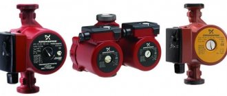
WILO YONOS PICO 25/1-8
GRUNDFOS UPS 25-70
Almost all manufacturers, including such “giants” as WILO and GRUNDFOS, post special programs for selecting a circulation pump on their websites. For the above-mentioned companies these are WILO SELECT and GRUNDFOS WebCam.
The programs are very convenient, they are quite easy to use
Particular attention should be paid to the correct entry of values, which often causes difficulties for untrained users
Buy a circulation pump
When purchasing a circulation pump, special attention should be paid to the selling company. There are currently a lot of counterfeit products on the Ukrainian market.
How can we explain that the retail price of a circulation pump on the market can be 3-4 times less than that of a representative of the manufacturer?
According to analysts, the circulation pump in the household sector is the leader in energy consumption. In recent years, companies have been offering very interesting new products - energy-saving circulation pumps with automatic power control. From the household series, WILO has YONOS PICO, GRUNDFOS has ALFA2. Such pumps consume several orders of magnitude less electricity and significantly save owners’ financial expenses.
Power
Power curves show power consumption as a function of supply, see Figure 2.7. Power is expressed in watts (W). Three types of power must be distinguished, see Figure 2.8.
- The power of the pumping unit transferred from an external source to the electric motor and controller (P1).
- Pump power transmitted by the electric motor to the shaft (P2).
- Net power transferred from the pump impeller to the liquid (P net).
Power consumption depends on the density of the liquid. Power curves are usually plotted for a standard liquid having a density of 1000 kg/m3, which corresponds to water at a temperature of 4°C. Thus, power measured on a liquid with a different density must be recalculated.
Typically, in ordering specifications, P1 is given for complete products, while P2 is given for pumps supplied with a standard motor.
Rotation frequency
Flow, pressure and power consumption vary depending on the pump speed. Comparison of pump characteristics is only possible if they are built for the same speed. It is possible to reduce the characteristics to the same speed using the equations below.
Speed control
By adjusting the pump speed, the QH, power and NPSH characteristics change. Recalculations of pump characteristics when its rotation speed changes are performed using similarity equations.
Subscript A in the equations indicates the original values, and subscript B indicates the modified values.
These equations allow us to obtain coherent points on the similarity parabola on the QH graph. The similarity parabola is shown in Figure 3.11.
Based on the relationship between the pump characteristic and its rotation speed, various control characteristics can be obtained. The most common control methods are the proportional control method and the constant pressure control method.
Selection of a circulation pump for a heating system criteria
When choosing a circulation pump for the heating system of a private home, they almost always give preference to models with a wet rotor, specially designed for operation in any household lines of varying lengths and supply volumes.
These devices have the following advantages compared to other types:
- low noise level,
- small overall dimensions,
- manual and automatic adjustment of the number of shaft revolutions per minute,
- pressure and volume indicators,
- suitable for all heating systems of individual houses.
Pump selection by number of speeds
To increase operating efficiency and save energy resources, it is better to take models with stepwise (from 2 to 4 speeds) or automatic control of the electric motor speed.
If automation is used to control the frequency, then energy savings compared to standard models reach 50%, which is about 8% of the electricity consumption of the entire house.
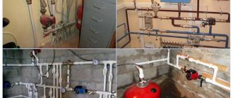
Rice. 8 The difference between a fake (right) and an original (left)
What else to pay attention to
When purchasing popular Grundfos and Wilo models, there is a high probability of counterfeiting, so you should know some of the differences between the originals and their Chinese counterparts. For example, German Wilo can be distinguished from a Chinese counterfeit by the following characteristics:
- The original sample is slightly larger in size and has a serial number stamped on its top cover.
- A raised arrow in the direction of fluid movement in the original was placed on the inlet pipe.
- The de-airing valve on the fake is yellow in brass color (the same color in the Grundfos analogues)
- The Chinese analogue has a bright shiny sticker on the reverse side indicating energy saving classes.
Rice. 9 Criteria for selecting a circulation pump for heating
Efficiency
The efficiency of a pumping unit (ηtotal) is the ratio of useful power to the power of the pumping unit. Figure 2.9 shows the efficiency curves for a pump (ηuseful) and for a pumping unit including an electric motor and controller (ηfull). Hydraulic efficiency refers to P2, and pumping efficiency refers to P1:
The efficiency is always less than 100% because the power of the pumping unit is always greater than the useful power due to losses in the controller, motor and pump. The efficiency of the pumping unit (controller, electric motor and pump) is the product of the individual efficiencies:
The flow rate at which the pump has maximum efficiency is called the best performance point or QBEP.
Why do you need a circulation pump?
It is no secret that most consumers of heating services living on the upper floors of high-rise buildings are familiar with the problem of cold radiators. Its cause is the lack of necessary pressure. Because if there is no circulation pump, the coolant moves slowly through the pipeline and, as a result, cools down on the lower floors
That is why it is important to correctly calculate the circulation pump for heating systems
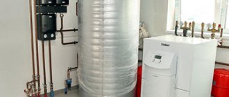
Owners of private households often face a similar situation - in the most remote part of the heating structure, the radiators are much colder than at the starting point. Experts consider the optimal solution in this case to be the installation of a circulation pump, as it looks like in the photo. The fact is that in small houses, heating systems with natural circulation of coolants are quite effective, but even here it would not hurt to think about purchasing a pump, since if you properly configure the operation of this device, heating costs will be reduced.
What is a circulation pump? This is a device consisting of a motor with a rotor immersed in a coolant. The principle of its operation is as follows: by rotating, the rotor forces a liquid heated to a certain temperature to move through the heating system at a given speed, resulting in the creation of the required pressure.
Pumps can operate in different modes. If you set the circulation pump in the heating system to maximum operation, a house that has cooled down in the absence of the owners can be warmed up very quickly. Then consumers, having restored the settings, receive the required amount of heat at minimal cost. Circulating devices come with a “dry” or “wet” rotor. In the first version, it is partially immersed in the liquid, and in the second - completely. They differ from each other in that pumps equipped with a “wet” rotor make less noise during operation.
NPSH - permissible cavitation reserve
Cavitation is the process of formation of vapor bubbles in areas where local pressure drops to the value of saturated vapor pressure. The degree of cavitation depends on how low the pressure in the pump is. During cavitation, pressure decreases and noise and vibration appear.
Cavitation first occurs in areas of lowest pressure in the pump, most often formed at the edges of the blades at the entrance to the impeller, see Figure 2.10.
The NPSH value is absolute and always positive. NPSH is measured in meters as head, see Figure 2.11. Since NPSH is measured in meters, there is no need to take into account the densities of different liquids.
There are two different values for NPSH: NPSHR and NPSHA.
NPSHA stands for available NPSH and determines how close to vaporization the liquid is in the suction line. NPSHA is determined by the formula:
NPSHR stands for required NPSH and expresses the lowest NPSH value required for acceptable pump operation. The absolute inlet pressure can be calculated from the given NPSHR value and the vapor pressure of the liquid by substituting NPSHR instead of NPSHA into formula (2.16).
To determine whether a pump can be safely installed in a system, the NPSHA and NPSHR for the highest flow and temperature values within the operating range should be found.
It is recommended to add a minimum safety margin of 0.5 m. Depending on the application, a larger safety margin may be required. For example, for noise-sensitive applications or for high-power pumps such as boiler feed pumps, the European Pump Manufacturers Association recommends applying a safety factor of SA=1.2 - 2.0 to the NPSH3% value.
The risk of cavitation in systems can be reduced or eliminated by the following measures:
- installing the pump lower than the liquid level in open systems;
- increasing pressure in closed systems;
- reducing the length of the suction line to reduce friction losses;
- increasing the cross-sectional area of the suction pipeline to reduce the speed of fluid movement and, as a result, reduce friction losses;
- elimination of local pressure drops resulting from bends and other obstacles in the suction pipeline;
- lowering the temperature of the liquid to reduce the vapor pressure.
The following two examples show how NPSH is calculated.
Example 2.1 Pump for supplying liquid from a well
The pump must supply liquid from a reservoir whose water level is 3 meters below the pump level. To calculate the NPSHA value, you need to know the friction loss in the suction line, water temperature and barometric pressure, see Figure 2.12.
Water temperature 40°C
Barometric pressure 101.3 kPa.
Pressure loss in the suction pipeline at the existing supply is 3.5 kPa.
At a water temperature of 40°C, the vapor pressure is 7.37 kPa and ρ is 992.2 kg/m3.
The values are taken from the table “Physical Properties of Water” at the end of the article.
For this system, the NPSHA expression in formula (2.16) can be written as follows:
Hsusp—water level relative to the pump. Hsuction can be above or below the pump and is expressed in meters. In this system, the water level is below the pump. Thus, Hsuction is negative, Hsuction = –3 m. The NPSHA value for the system is:
A pump designed to operate in the system under consideration must have an NPSHR value of less than 6.3 m minus a safety margin of 0.5 m. Thus, at the existing flow, the pump requires an NPSHR value less than 6.3 - 0.5 = 5.8 m.
Example 2.2 Pump in a closed system
In a closed system there is no free surface of water to use as a reference plane. This example shows how a pressure sensor located above the reference plane can be used to determine the absolute pressure in a suction line, see Figure 2.13.
Measured relative static pressure on the suction side pstat.in = -27.9 kPa. Thus, there is negative pressure at the pressure gauge installation point. The pressure gauge is installed above the pump. Consequently, the difference between the height of the pressure gauge and the height of the entrance to the impeller has a positive value Hinsu = +3 m. The speed in the pipe where the pressure is measured creates an additional dynamic pressure of 500 Pa.
Barometric pressure 101 kPa.
Calculated friction losses in pipes between the measuring point (pstat.in.) and the pump H pipe losses. = 1m.
System temperature 80°C.
Vapor pressure pn.p. = 47.4 kPa, density ρ = 973 kg/m3, values taken from the table “Physical properties of water”.
For this system, Formula 2.16 for NPSHA is:
Despite the negative pressure in the system, the NPSHA value for the existing flow rate exceeds 4 m.
Factors affecting the calculation
When calculating pump power, the following number of factors must be taken into account:
- Well depth.
An accurate determination of the parameter is necessary for the correct calculation of the source flow rate. Moreover, this will allow you to correctly select the pump according to the depth of immersion and the height of water rise.
- Static level.
This is the distance from the water surface to the surface of the earth when the water intake source is not in use. The downtime of the well before the start of measurement varies from 1 hour to a day.
For proper operation of the well, it is necessary to accurately determine the static and dynamic levels Source teployug.ru
See also: Catalog of companies that specialize in engineering systems (heating, water supply, sewerage and others) and related work
It reaches its maximum value during spring floods, and its minimum value during dry periods. Therefore, it is always better to measure it during the summer period without rain.
- Dynamic level.
This is the distance from the surface of the earth to the water surface at full water intake. The difference between static and dynamic levels is maximum in shallow wells - low-pressure sandy and low-flow Abyssinian wells, and is almost completely absent in deep artesian sources.
Determining the dynamic level when calculating the installation depth of a submersible pump is of great importance. Since the magnitude of the external pressure of the water column on the device in the off state will depend on this. In the optimal case, the equipment should be immersed at least 1-2 meters below the dynamic mark.
- Volume consumed.
In order to calculate the pressure and other characteristics of the installed pump, it is necessary first of all to determine how much water it will pump daily. The amount depends on the type and number of receivers, as well as how many people will use them. Each plumbing fixture has its own parameter value.
The volume of water consumed in the house depends on the specific type of consumer and their amount Source proekt-sam.ru
For example:
- Sink with tap – 250 l/h.
- Washbasin with mixer – 180 l/h.
- Bath with mixer – 300 l/h.
- Shower cabin – 115 l/h.
- Toilet with tank - 83 l/h.
However, in the calculations it is also necessary to take into account the utilization factor, which, as a rule, varies from 0.15 to 0.5 for different devices. In this case, the total consumed volume should not exceed the well flow rate.
- Diameter of well pipes or well rings.
For shallow narrow wells of the Abyssinian type, external centrifugal pumps with a submerged water intake pipe are used. Since it is not possible to install standard submersible models with a body diameter of 4 inches in them. They require a borehole pipe with an internal diameter of at least 100 mm.
For high-performance models with a 6-inch body, a pipe of at least 150 mm is required. If a well is used on the site as a water source, special requirements are also imposed on the diameter of the rings - subject to the installation of special submersible electric pumps with a float switch. The latter should be located on the water surface at least 300 mm from the central axis of the device.
Schematic illustration of a water supply system for a home Source 7filtrov.shop
- Water composition.
Depending on the type of water intake source, the composition of the water can vary significantly. Therefore, for each variety it is recommended to use its own type of pump, well suited to specific conditions:
- Inexpensive Abyssinian wells up to 8 m deep are serviced by vortex or centrifugal pump types. The pumped water is quite clean.
- Sandy springs are characterized by greater depth and the content of solid particles in the water. If the water is relatively clean, deep-well centrifugal pumps are used, and if there is significant turbidity, screw-type models are used.
- Artesian wells with a hard limestone bottom are serviced by vortex and centrifugal electric pumps.
At the same time, in order to accurately calculate the pressure and other important characteristics of the pump, it is necessary to take into account the hydraulic resistance factor in water filters. Since, due to poor water quality, they are often installed in the water intake system.
When calculating pump characteristics, it is necessary to take into account the hydraulic resistance of the water filter Source ichip.ru
Axial load
The axial load is the sum of the forces acting on the shaft in the axial direction, see Figure 2.14. The axial load is mainly caused by the pressure difference between the front and rear impeller disks.
The magnitude and direction of the axial load can be used to determine bearing size and motor design. Pumps with upward loads require fixed bearings. In addition to the axial load, it is necessary to take into account the forces acting on the shaft due to the pressure in the system. An example of an axial load curve is shown in Figure 2.15.
The axial load is related to the head and is therefore proportional to the square of the speed.
Constructions
There are only two types:
"Wet"
The device is placed in a liquid, which is a cooling lubricant for a running engine.
Among the advantages of “wet” type pumps are:
- Quiet operation.
- Light weight and size.
- Economical energy consumption.
- Long-term work without interruptions.
- Ease of repair.
They have only one drawback - low efficiency. It does not exceed 50%, so such devices are better suited for small domestic buildings.
"Dry"
Its design is different in that the rotor does not come into contact with the liquid.
Compared to the previous type, its efficiency is 80%, but there are the following disadvantages:
- Noise during operation , so it is better to install them in a special enclosed area;
- High requirements for cleanliness of liquid and air to avoid depressurization of sealing rings.
“Dry” are produced in three variations: horizontal, vertical and block. This setting is based on the location of the motor inside the device.
Calculation of internal combustion engine power based on injector performance
An equally effective indicator of the power of a car engine is the performance of the injectors. Previously, we looked at its calculation and relationship, therefore, it will not be difficult to calculate the amount of horsepower using the formula. The estimated power is calculated according to the following scheme:
Where, the load factor is no more than 75-80% (0.75...0.8), the mixture composition at maximum performance is somewhere around 12.5 (rich), and the BSFC coefficient will depend on what kind of engine you have, naturally aspirated or turbocharged (atmo - 0.4-0.52, for turbo - 0.6-0.75).
Having found out all the necessary data, enter the indicators into the appropriate cells of the calculator and by clicking the “Calculate” button you will immediately receive a result that will show the real engine power of your car with a slight error. Please note that you do not necessarily need to know all the parameters presented; you can clear the power of the internal combustion engine using a separate method.
The value of the functionality of this calculator lies not in calculating the power of a stock car, but if your car has been tuned and its weight and power have undergone some changes.
Tips for choosing
- Previously it was said that pumps can be with “dry” and “wet” rotor types , as well as using manual or automatic speed control systems. Experts recommend using circulation devices whose rotor is immersed in liquid. This design is not only quieter, but also handles the load better.
- When choosing a circulation pump, you should pay attention to the housing material. Stainless steel, brass or bronze are best, but cast iron products are best avoided - they will not last long under such conditions.
- The efficiency of the device will depend not only on the factory parameters, but also on correctly performed calculations, so do them twice.
- Author: Maria Sukhorukikh
Rate this article:
- 5
- 4
- 3
- 2
- 1
(0 votes, average: 0 out of 5)
Share with your friends!
Best manufacturers and cost
Nowadays, quite a lot of manufacturers are engaged in the manufacture of circulation pumps. Among them: Italian companies General Hydraulic, Dab, Speroni, as well as German ones - Unitherm, Wilo and Grundfos. The last two brands provide a wide range of their products, so among them you can easily select the necessary product of any parameters.
The cost of such products directly depends on technical characteristics, such as power and pressure, as well as on the factory equipment and additional services (control panel, speed switching, material and types of seals).
Also, the reputation of the manufacturer is considered an important fact. As mentioned earlier, the best companies produce guaranteed reliable products, but they also cost more.
As an option, let’s consider the cost of two popular models with approximately the same parameters: one is cheap, and the second is a popular model among the best companies.
This will make it possible to determine the price range:
- Vortex HZ 401 – DN25 – 3430 rub.
- Grundfos ALPHA2 25-40 – 9560 rub.
Calculation of engine power based on air flow
The same approximate calculation of engine power can be determined by air flow. The function of such a calculation is available to those who have an on-board computer installed, since it is necessary to record the flow rate when the car engine, in third gear, is spun up to 5.5 thousand revolutions. We divide the resulting value from the mass air flow sensor by 3 and get the result.
The formula for calculating the power of an internal combustion engine based on air flow ultimately looks like this:
Gw [kg]/3=P[hp]
This calculation, like the previous one, shows gross power (bench test of the engine without taking into account losses), which is 10-20% higher than the actual one. It is also worth considering that the readings of the mass air flow sensor are highly dependent on its contamination and calibrations.
How to calculate power by engine volume
If you do not know the torque of your car’s engine, then to determine its power in kilowatts you can also use a formula of this type:
Ne = Vh * pe * n/120
(kW), where:
- Vh — engine volume, cm³
- n — rotation speed, rpm
- pe is the average effective pressure, MPa (for conventional gasoline engines it is about 0.82 - 0.85 MPa, for forced ones - 0.9 MPa, and for diesel engines from 0.9 and to 2.5 MPa, respectively).
To obtain engine power in “horses” rather than kilowatts, the result should be divided by 0.735.
The influence of installation on the pressure value
When installing a pump, the following series of errors are often made, which directly or indirectly affect the reduction in pressure:
- Mismatch between the diameters of the suction pipe and water supply . Often, when organizing a water supply system, pipes are selected in such a way that a significant difference arises between the internal diameter of the water supply pipe and the suction pipe of the pumping unit, which naturally cannot but negatively affect the pressure and pressure of water at the points of consumption.
- Connect directly to the hose . Low-performance models can be used in this form. However, even average household analogues will experience a significant reduction in performance indicators. Because under pressure the elastic material will simply shrink. As a result, the supply will either decrease significantly or stop altogether.