When operating heating systems with natural coolant circulation, owners of apartments and private houses are often faced with the problem of insufficient heating of radiators installed in remote rooms.
It all depends on the length of the heating circuit. If its length is more than 30 meters, the level of water pressure becomes insufficient to maintain the required temperature at its most distant points.
To achieve stable operation of the equipment, devices are used that ensure rhythmic circulation of the coolant. Preliminary calculation of a pump for a heating system makes it possible to determine the parameters necessary to select the most optimal model.
How to determine the required pressure of the circulation pump
The head of centrifugal pumps is most often expressed in meters.
The pressure value allows you to determine what hydraulic resistance it can overcome. In a closed heating system, the pressure does not depend on its height, but is determined by hydraulic resistance. To determine the required pressure, it is necessary to perform a hydraulic calculation of the system. In private homes, when using standard pipelines, as a rule, a pump that develops a pressure of up to 6 meters is sufficient. You should not be afraid that the selected pump is capable of developing greater pressure than you need, since the developed pressure is determined by the resistance of the system, and not by the number indicated in the passport. If the maximum pressure of the pump is not enough to pump liquid through the entire system, there will be no circulation of liquid, so you should choose a pump with a headroom reserve
.
Resistance
In addition to the need to push water to a certain height, the pump must be able to overcome the resistance created in the pipeline. A pipe that is too narrow will increase resistance and system performance will decrease, while a pipe that is too wide will require unnecessary costs. The diameter of the water conduit should be optimally selected to avoid unnecessary resistance.
To calculate the resistance, check out the pressure loss graph for a pipe of a specific type and diameter: this way you can calculate the losses for a certain volume of water. If there is no graph or you don’t want to count, use the simple recommendation below:
Recommended HDPE pipe diameter:
- flow up to 1.5 m3/hour – 25 mm
- flow up to 3 m3/hour – 32 mm
Recommendations for calculating pump power for water wells.
Sometimes people ask the following questions: recommend a good pump for a well, since the old one no longer copes with its task.
Answers to the most common questions will be given below in the form of recommendations from experts.
1. When choosing a pump, try not to give preference to options with vibration, although their price is lower. This type of equipment is more suitable for ordinary wells, since their communications are covered with sand over time.
2. It is better to choose centrifugal type submersible pumps. This will prevent the well from filling up with sand.
3. To obtain better quality water, install the pump at a distance of at least 1 m from the filter.
4. When using water, it is necessary to take into account not only average values, but also peak values. Also make sure that there is enough water for technical purposes (watering the garden, washing the car, etc.).
5. To ensure good water pressure, you must select a pump with a power reserve of 20% of the selected value. This will create excess pressure in the system and provide excellent water pressure. Factors such as silting of water pipes and the use of filters contribute to a decrease in pressure. It will not be possible to carry out this type of calculation yourself without the necessary knowledge and skills, so it is better to turn to professionals for help.
6. Try to lower the pump 1 m below the dynamic water level. This measure will prevent the engine from being cooled by water coming from outside.
7
To protect against power surges, it is recommended to install stabilizers, since for a submersible pump it is very important that the network has a stable voltage and current. This will further protect your equipment and extend its service life.
8
Please note that the diameter of the pump must be at least 1 cm smaller than the diameter of the well itself. This will extend the life of the pump and simplify the procedure for installing/dismantling equipment
For example, if a well has a diameter of 76 cm, then the pump must be selected with a diameter of no more than 74 cm
For example, if a well has a diameter of 76 cm, then the pump must be selected with a diameter of no more than 74 cm.
What type of accumulator is needed?
Hydraulic accumulator selection table.
To select the right pump, you need to pay attention to which hydraulic accumulator will be used. Its purpose is to accumulate a certain volume of water to prevent the pump itself from turning on frequently. When a certain volume of water is reached, the pump turns off until the water is used up
Each pump has a permitted number of starts per hour, which is not recommended to be exceeded
When a certain volume of water is reached, the pump turns off until the water is used up. Each pump has a permitted number of starts per hour, which is not recommended to be exceeded.
Typically these are 20 starts, which, in the absence of a hydraulic accumulator, will be carried out every time the tap is opened. But if there is a tank, such inclusions will be rare, which will extend the service life of all equipment.
- Qmax is the maximum value of water flow;
- Pset – pressure when the pump is turned on;
- ΔР is the difference that is observed when the pump is turned on and off;
- Nmax is the permissible number of switches on and off per hour, usually indicated by the manufacturer for each model separately;
- K = 0.9.
When choosing a pump, it is necessary to take into account that the pressure of the air mass in it is always 0.8-0.9 bar.
Defining Variables
The performance of a centrifugal pump is affected by the following components:
- water pressure;
- required power consumption;
- impeller size;
- maximum liquid suction height.
So, let's look at each of the indicators in more detail, and also provide calculation formulas for each of them.
Calculation of the performance of a centrifugal pump unit is carried out according to the following formula:
W = l1*(n*d1 – b*n)*c1 = l2*(n*d2 – b*n)*c2
The designation of this formula is as follows: W – pump performance, measured in m3/s; l1,2 – width of the impeller according to diameters d1,2; d1 – diameter of the suction pipe; d2 – impeller diameter; b – thickness of the impeller blades; n – number of blades; p – number “pi”; с1,2 – meridian sections of the inlet and outlet pipes.
You may be interested in an article on the classification of centrifugal pumps.
Read the article about centrifugal self-priming pumps here.
The water pressure created by a centrifugal pump is calculated by the formula:
N = (h2 – h1)/(p * g) + Ng + sp
The variables in the formula indicate: N – head height, measured in meters; h1 – pressure in the liquid intake tank, measured in Pa; h2 – pressure in the liquid receiving tank; p – density of the liquid that is pumped by the pump, measured in kg/m3; g is a constant value indicating the acceleration of gravity; Ng – indicator of the required height of liquid rise; sp – sum of fluid pressure losses.
The required power consumption is calculated using the following formula:
M = p*g*s*N
The formula variables mean: M – required power consumption; p – density of the pumped liquid; g is the magnitude of the acceleration of free fall; s – required volume of liquid flow; N – pressure height.
The maximum liquid suction height is calculated by the formula:
Nv = (h1 – h2)/(p * g) – sp – q2/(2*g) – k*N
The designation of the variables is as follows: Nv – liquid suction height; h1 – pressure in the intake tank; h2 – fluid pressure on the impeller blades; p – density of the liquid being pumped; g – free fall acceleration; sp is the amount of losses in the incoming pipeline due to hydraulic resistance; q2/(2*g) – liquid pressure in the suction line; k*N – losses depending on the added resistance; k – cavitation coefficient; N is the pressure created by the pump.
Can installation affect the pressure value?
Considering the simplicity, even primitiveness of the design of the pumps, as well as the availability of detailed installation instructions, many modern men take on the work on their own, that is, without the help of professionals. This behavior is most often associated with the desire to save money: not everyone is willing to pay not only for a pump or pumping station, but also for the services of a specialist. Considering that the pump's pressure is the main characteristic of its operation, no one is ready to lose. That is why the question suggests itself: to what extent can installation carried out independently affect the amount of pressure.
It would seem that we connect one pipe to the suction pipe, the other to the one responsible for the pressure, supply power - and you're done. In practice, the slightest mistake can not only negatively affect the water pressure, but also significantly reduce the duration of work.
Design differences
Hydraulic pumps come in the following design types:
Why in meters?
A pump for water pressure and any other liquid is a very popular device, without which it is difficult to imagine life in a private home. Many consumers still do not understand why pressure is measured in meters.
The pressure of a centrifugal pump, like any other, is usually measured in meters. Of course, such a system raises many questions. First of all, this has happened historically; everyone has long been accustomed to this designation and does not intend to change anything. And, of course, this is convenient, because you don’t have to resort to using other units of measurement or make complex mathematical calculations. The amount of pressure, calculated in meters, gives us information that the pump can lift the liquid to a given height.
general information
The autonomous water supply system of a private house consists of several components:
- water source:
- A well is an artificial excavation-mine dug to collect underground groundwater in the surface aquifer to a depth of 10~15 m and reinforced against collapse.
- Wells . They are carried out by drilling and come in several types: Gravity : “on sand” - up to 50 m, “on limestone” - up to 150 m.
- Artesian - over 150 m.
- Abyssinian and others.
- Water consumers on site and in the house : sinks, sinks, baths, saunas, swimming pools, irrigation.
- Supply and distribution system : pumps, storage tanks, pipelines.
When designing an autonomous system, the first question that arises is the selection of a pump for the water supply of a private home, as one of the most important and, if we talk about the quality of work and durability, the most expensive part of the hydraulic equipment. And its choice is determined, first of all, by the type of water source on the site , and then by the selected water supply scheme.
Submersible pump pressure
That is why a submersible pump is considered one of the safest and most reliable. Its pressure is calculated by the formula:
H = H height + H losses + H spout, where:
H height - height difference between the location of the pump and the highest point of the water supply system;
H losses - possible hydraulic losses that occur when liquid moves through a pipe; they are primarily associated with friction of the liquid against the walls of the pipe;
H spout is the pressure on the spout that allows you to use all plumbing fixtures (usually in the range of 15-20 meters).
We have already established that the pump head is the pressure required to push the liquid to a given height. Circulation pumps have found themselves in heating systems; it is with their help that the uninterrupted circulation of the heat source in the system is ensured
Of course, it is necessary to approach the choice of a circulation pump more consciously and demandingly, understanding that the efficiency and uninterrupted operation of its use largely depends on this, which is so important for apartment buildings. Such pumps are reliable, efficient and have shown excellent performance even in apartment buildings. Of course, such a pump should also be selected based on the pressure
The pressure of the circulation pump has no connection and, accordingly, no dependence on the height of the building. The main thing here is the hydraulic resistance of the route. And here for the calculation you will need the following formula:
Of course, such a pump should also be selected based on pressure. The pressure of the circulation pump has no connection and, accordingly, no dependence on the height of the building. The main thing here is the hydraulic resistance of the route. And here for the calculation you will need the following formula:
H = (R * L + Z sum) / (p * g), where:
R - losses;
L is the length of the pipeline, measured in meters;
Z sum - the total number of the safety factor for the structural elements of the pipeline (for fittings and fittings this value is 1.3; for thermostatic valves - 1.7; and for mixers - 1.2);
p is the density of water, we remember from the school physics course that it is 1000 kg/m3;
g is the acceleration due to gravity, the value of which is taken as an average value of 9.8 m/s2.
It turns out that, knowing all the basic parameters, it is quite simple to determine the water pressure that you need in a particular situation; for this you do not have to involve specialists.
Checking the selected electric motor a. Checking the rudder shift duration
For the selected pump, look at the graphs of the dependence of the mechanical and volumetric efficiency on the pressure created by the pump (see Fig. 3).
4.1. We find the moments arising on the electric motor shaft at different steering angles:
,
where: M
α – torque on the electric motor shaft (Nm);
Q
mouth – set pump capacity;
P
α – oil pressure created by the pump (Pa);
P
tr – pressure loss due to oil friction in the pipeline (3.4÷4.0)·105 Pa;
n
n – pump speed (rpm);
η
r – hydraulic efficiency associated with fluid friction in the working cavities of the pump (for rotary pumps ≈ 1);
η
mech - mechanical efficiency, taking into account friction losses (in oil seals, bearings and other rubbing parts of pumps (see graph in Fig. 3).
We enter the calculation data in Table 4.
4.2. We find the rotation speed of the electric motor for the obtained torque values (based on the constructed mechanical characteristics of the selected electric motor - see paragraph 3.6). We enter the calculation data in Table 5.
Table 5
| α° | n, rpm | ηr | Qα, m3/s |
| 5 | |||
| 10 | |||
| 15 | |||
| 20 | |||
| 25 | |||
| 30 | |||
| 35 |
4.3. We find the actual pump performance at the obtained electric motor speeds,
where: Q
α – actual pump performance (m3/sec);
Q
mouth – installed pump capacity (m3/sec);
n
– actual speed of rotation of the pump rotor (rpm);
n
n – nominal speed of rotation of the pump rotor;
η
v – volumetric efficiency, taking into account the reverse bypass of the pumped liquid (see graph 4.)
We enter the calculation data in table 5. We build a graph Q
α
= f ( α )
– see fig.
4 .
Rice. 4. Graph Q
α
= f ( α )
4.4. We divide the resulting graph into 4 zones and determine the operating time of the electric drive in each of them. We summarize the calculation in Table 6.
Table 6
| Zone | Zone boundary angles α° | Hi (m) | Vi (m3) | Qav.z (m3/sec) | ti (sec) |
| I | |||||
| II | |||||
| III | |||||
| IV |
4.4.1. Find the distance covered by the rolling pins within the zone
,
where: H i
– distance covered by rolling pins within the zone (m);
R o
– distance between the axes of the stock and rolling pins (m).
4.4.2. Finding the volume of oil pumped within the zone
,
where: V i
– volume of pumped oil within the zone (m3);
m
cyl – number of pairs of cylinders;
D
– plunger (rolling pin) diameter, m.
4.4.3. Find the duration of the rudder shift within the zone
,
where: t i
– average duration of rudder shift within the zone (sec);
Q
av
i
– average productivity within the zone (m3/sec) – taken from the graph in clause 4.4. or calculate from table 5).
4.4.4. We determine the operating time of the electric drive when shifting the steering wheel from side to side
t
lane
= t 1 + t 2 + t 3 + t 4 + t o
,
where: t
per – time of shifting the rudder from side to side (sec);
t 1 ÷ t 4
– duration of transfer in each zone (sec);
t o
– time to prepare the system for action (sec).
4.5. We compare t shift with T (time of shifting the rudder from side to side at the request of RRR), sec.
t
lane
≤ T
(30 sec)
Supply (performance) of pumping equipment
This is one of the main factors to consider when choosing a device. Supply – the amount of coolant pumped per unit of time (m3/hour). The higher the flow, the greater the volume of liquid that the pump can pump. This indicator reflects the volume of coolant that transfers heat from the boiler to the radiators. If the supply is low, the radiators will not heat well. If the performance is excessive, home heating costs will increase significantly.
The power of circulation pumping equipment for a heating system can be calculated using the following formula: Qpu=Qn/1.163xDt [m3/h]
In this case, Qpu is the supply of the unit at the design point (measured in m3/hour), Qn is the amount of heat consumed in the area that is heated (kW), Dt is the temperature difference recorded on the forward and return pipelines (for standard systems this is 10- 20°C), 1.163 – indicator of the specific heat capacity of water (if another coolant is used, the formula must be adjusted).
Types of power of the device for the well
When releasing devices, the manufacturer uses the following designations for power types:
- P1 (kW). Input electrical power is that which the electric motor takes from the electrical network.
- P2 (kW). On the shaft of the electric motor - the one that it gives to the shaft. The input electric power of pump P1 is equal to the shaft power of electric motor P2 divided by the efficiency of the electric motor.
- P3 (kW). The input indicator of the hydraulic pump is equal to the value P2 when the coupling that connects the shaft of the device and the shaft of the electric motor does not consume electricity.
- P4 (kW). The useful power of submersible hydraulic pumping equipment is that which comes out during operation in the form of water flow and pressure.
Without relevant experience, it is not recommended to install the pump yourself. You can calculate the indicator online; there is a special calculator.
Calculations and example
To choose the right circulation pump, you need to make preliminary calculations. More precisely, you need to know the following values:
- Qn – heat source power, kW;
- Qpu – volumetric flow, m3/h;
- Hpu is the pressure required to overcome the hydraulic resistance in the system, m.
For easier understanding, all calculations will be carried out using the example of a private house with an area of 340 m2.
The power of the heat source is calculated using the formula Qn=, where Sn is the area of the heated room, Qsp is the specific heat requirement, that is, how many Watts per m2 are required to make the house cozy and warm. For buildings with more than two apartments, this value is 70 W/m2, and for detached houses, for example, private houses, 100 W/m2.
Since a private house is given as an example, the second number is taken for calculations
Now you can calculate the volumetric flow: Qpu=, where the number 1.163 is the specific heat capacity of water. If the heating system uses a different coolant, then instead of this number it is necessary to put the corresponding coefficient. — calculated temperature difference in the forward and return pipelines. For standard systems it is from 10 to 20°C.
For example, an average difference of 15°C is used:
Next, you need to calculate the amount of pressure sufficient to overcome all the resistance of the main line. To do this, you need to determine the losses in the longest section of the network, that is, to the farthest radiator.
Hpu=, where R – friction losses in heating system pipes – from 50 to 150 Pa/m. The first number is used for networks with large pipe diameters, since there is less pressure loss in them, and the second number is used for smaller pipes. L is the return and feed length for the longest branch. If it is unknown, then you can calculate it using the following formula: (length of the house + width of the house + height of the house)x2.
For example, the value of L is unknown, therefore:
ZF – resistance coefficient of fittings and shut-off valves. Its value ranges from 0.3 to 2.2 depending on the presence of a thermostatic valve. If it is missing, then the number 0.3 is taken.
In the example above it is, so the value ZF = 2.2 is used.
All calculations are substituted into the formula:
Knowing now all 3 values, you can begin choosing a device.
How to choose a circulation pump based on the found values
First you need to decide on the manufacturer. Experts recommend choosing not the cheapest models, since the quality of their parts and declared characteristics often do not meet expectations. The most popular and reliable manufacturers are Grundfos, Wilo, Lowara, Ebara, DUB, Ensyco and others.
Each circulation pump model has markings indicating the size of the connecting thread, electricity consumption, pressure force and much more. Immediately below the name are the most important numbers: 25-60, 32-60 and so on. The first number is the connecting size in mm, the second is the pressure, that is, to what height the device can raise the water column. The number 60 means 6 m, 40 means 4 m, 80 means 8 m.
To choose the model that best suits the heating system, you will need a technical data sheet or a pump catalog (available in the store). The calculations found should be considered average and the most optimal.
The device passport or catalog contains diagrams indicating pressure and volumetric flow values. There are 3 lines on the chart
You need to pay attention to the second midline. Substituting the resulting numbers in the calculations, they should be closer to its center, or rather, in the third part, located in the middle
In this case, the selected model will cope with the task assigned to it better than others and will serve for a long time.
If you are not sure of the calculations made, it is best to contact specialists so that there are no problems with heating the room in the future.
https://youtube.com/watch?v=TGcQpF5AZPE%3F
Table 4.3 - Calculation of profiling of a cylindrical blade
| No. of points | r, mm | b, mm | sch | t | d | channel d/t | ||
| 1 | 2 | 3 | 4 | 5 | 6 | 7 | 8 | 9 |
| 1 | 69 | 13,4 | 0,8049 | 2,775 | 0,290 | 47,10 | 3 | 0,06369 |
| 2 | 74 | 12,5 | 0,7990 | 2,754 | 0,290 | 49,34 | 4 | 0,08106 |
| 3 | 93 | 10 | 0,7959 | 2,743 | 0,290 | 52,03 | 5 | 0,09609 |
| 4 | 111 | 8,4 | 0,7927 | 2,732 | 0,290 | 56,52 | 6 | 0,10615 |
| 5 | 130 | 7,2 | 0,7898 | 2,722 | 0,290 | 58,31 | 6 | 0,10289 |
| 6 | 147 | 6,4 | 0,7819 | 2,716 | 0,290 | 61,01 | 5 | 0,08195 |
| 7 | 168 | 5,6 | 0,7848 | 2,705 | 0,290 | 62,80 | 4 | 0,06369 |
| 8 | 181 | 5,2 | 0,7814 | 2,693 | 0,290 | 66,39 | 3 | 0,04518 |
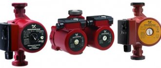
Types of circulation pumps
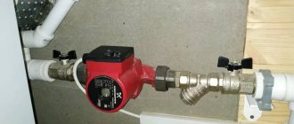
A pump with a “wet” rotor is made of stainless steel, cast iron, bronze or aluminum. Inside there is a ceramic or steel motor
To understand how this device works, you need to know the differences between the two types of circulation pumping equipment. Although the fundamental design of a heating system based on a heat pump does not change, the two types of such units differ in their operating features:
- A pump with a “wet” rotor is made of stainless steel, cast iron, bronze or aluminum. Inside there is a ceramic or steel motor. The technopolymer impeller is mounted on the rotor shaft. When the impeller blades rotate, the water in the system is set in motion. This water simultaneously functions as an engine cooler and a lubricant for the working elements of the device. Since the “wet” device circuit does not provide for the use of a fan, the operation of the unit is almost silent. Such equipment only works in a horizontal position, otherwise the device will simply overheat and fail. The main advantages of a wet pump are that it does not require maintenance and also has excellent maintainability. However, the efficiency of the device is only 45%, which is a minor drawback. But for domestic use this unit is perfect.
- A pump with a “dry” rotor differs from its counterpart in that its motor does not come into contact with the liquid. As a result, the unit has less durability. If the device operates “dry,” then the risk of overheating and failure is low, but there is a risk of leakage due to abrasion of the seal. Since the efficiency of a dry circulation pump is 70%, it is advisable to use it to solve utility and industrial problems. To cool the engine, the device circuit provides for the use of a fan, which causes an increase in the noise level during operation, which is a disadvantage of this type of pump. Since in this unit water does not serve as a lubricant for working elements, during operation of the unit it is necessary to periodically carry out technical inspection and lubricate parts.
In turn, “dry” circulation units are divided into several types according to the type of installation and connection to the engine:
- Console. In these devices, the engine and housing have their own place. They are separated and firmly fixed on it. The drive and working shafts of such a pump are connected by a coupling. To install this type of device, you will need to build a foundation, and maintaining this unit is quite expensive.
- Monoblock pumps can be used for three years. The body and engine are located separately, but are combined by a monoblock. The wheel in such a device is installed on the rotor shaft.
- Vertical. The service life of these devices reaches up to five years. These are sealed advanced units with a seal on the end side made of two polished rings. For the manufacture of seals, graphite, ceramics, stainless steel, and aluminum are used. When the device is running, these rings rotate relative to each other.
There are also more powerful devices on sale that have two rotors. This dual circuit allows you to increase the performance of the device at maximum load. If one of the rotors fails, the second can take over its functions. This allows not only to enhance the operation of the unit, but also to save energy, because with a decrease in heat requirements, only one rotor works.
Technical aspects of aluminum batteries
To install an autonomous heating system, it is necessary not only to carry out installation work in accordance with current regulations, but also to choose the right aluminum radiators. This can only be done after a thorough study and analysis of their properties, design features, and technical characteristics.
Classification and design features
Manufacturers of modern heating equipment make sections of aluminum radiators not from pure aluminum, but from its alloy with silicon additives. This allows the products to be corrosion resistant, more durable and extend their service life.
Today, the retail chain offers a wide range of aluminum radiators, differing in appearance, represented by such products as:
- panel;
- tubular.
According to the constructive solution of a single section, which are:
- Solid or cast.
- Extruded or composed of three separate elements, internally secured to each other with bolts with foam rubber or silicone gaskets.
Batteries are also differentiated by size.
Standard sizes with a width of 40 cm and a height of 58 cm.
Low, up to 15 cm high, which makes it possible to install them in very limited spaces. Recently, manufacturers have been producing aluminum radiators of this series of “plinth” design with a height of 2 to 4 cm.
Tall or vertical. With a small width, such radiators can reach a height of up to two or three meters. This working height arrangement helps to heat large volumes of air in the room quite effectively. In addition, this original design of radiators also performs a decorative function.
The service life of modern aluminum radiators is determined by the quality of the source material and does not depend on the number of its constituent elements, their sizes and internal volume. The manufacturer guarantees their stable operation with proper use for up to 20 years.
Main performance characteristics
Comparative characteristics
Technical characteristics and design solutions of aluminum radiators are developed to ensure convenient and reliable heating of rooms. The main components characterizing their technical properties and operational capabilities are the following factors.
Operating pressure. Modern aluminum radiators are designed for pressure levels from 6 to 25 atmospheres. To guarantee these indicators, in the factory, each battery is tested at a pressure of 30 atmospheres. This fact makes it possible to install this heating equipment in any heating system where the possibility of water hammer formation is excluded.
Power. This indicator characterizes the thermodynamic process of heat transfer from the surface of the heating battery to the environment. It indicates how much heat in watts the device can produce per unit time.
By the way, it occurs using the method of convection and thermal radiation in a ratio of 50 to 50. The numerical value of the heat transfer parameter of each section is indicated in the device passport.
When calculating the number of batteries required for installation, their power plays a primary role. The maximum heat transfer of one section of an aluminum heating radiator is quite high and reaches 230 Watts. This impressive figure is explained by the high heat transfer ability of aluminum.
This means that it requires less energy to heat it than its cast iron counterpart.
The temperature range for heating the coolant in aluminum batteries exceeds 100 degrees.
As a reference, a standard section of an aluminum radiator with a height of 350–1000 mm, a depth of 110–140 mm, with a wall thickness of 2 to 3 mm, has a coolant volume of 0.35–0.5 liters, and is capable of heating an area of 0.4– 0.6 square meters.
How to increase the productivity of a centrifugal pump?
A centrifugal pump is not designed to create one specific set of operating conditions, as the buyer would like. This type of pump is designed to provide the full performance range as indicated on the graph curve.
To fully appreciate the behavior of the pump curve and the relationship between head and performance of a centrifugal pump, imagine that the pump is discharging water into a straight vertical pipe. If the pipe is located high, the liquid will eventually reach a certain level, above which it will no longer be able to rise. This is how the maximum pressure that a centrifugal pump can develop with this pipe position is determined. It may work, but it will not be able to move the liquid beyond this level. In this case, the pumped liquid will stop in the equipment housing, but will not pass through the pump. Therefore, at maximum pump performance there will be zero head.
In this case, you can make a hole in the pipe at a lower level. Thus, the pump will constantly develop more and more capacity. If you transfer this to a graph, you can determine the performance of the pump. The curve will not stop at zero pressure. But, given pump failures above a certain power, the curve is usually interrupted. This curve defines:
- the performance that this pump can develop;
- a measure of the total head when the pump is running at a certain speed with a given impeller diameter.
You cannot rely entirely on the curve readings. The actual conditions on the curve will depend on the system in which it operates. This means that the system controls the pump and determines the operating conditions, regardless of the production pressure parameters.
Factors such as gravity and friction can impede the flow of fluid from one location to another. To reduce gravity, the liquid must rise vertically. The distance between the source and the final point of fluid transport is called the total static head. It is not a flow rate variable, and a graph comparing the two will appear as a straight horizontal line.
Another important characteristic of a pump is friction. This term defines resistance to flow. It is calculated from losses from all sources (for example, in filters, heat exchangers). Loss data can be measured by measuring the inlet and outlet pressures. As the flow increases, friction losses also increase. This happens at great speed.
The pressure at the suction source and the drain tank is also taken into account. If these are closed vessels with different pressures, the resulting difference is added to the total pressure indicator. In this case, the graph will be constructed differently: the curve will start at the level of static pressure and will gradually increase depending on the increase in pressure flow.
If you select the right pump, the performance will intersect the curve at a point. This point will indicate the operation of the equipment. There are also several ways to regulate the operation of a centrifugal pump:
- Changing the impact on the water pumping system. This is the simplest method, the principle of which is to use a valve. It is installed in the pressure pipeline. There is a potential risk of cavitation with such experiments. This is explained by the fact that the position of the valve can influence the operating point.
- Pump speed control. This is an effective way to reduce losses that will affect the power of the centrifugal pump. Allowed only in equipment models with the ability to regulate the rotation speed.
- A method associated with changing the technical characteristics of the unit. With the help of auxiliary elements, you can adjust the pressure force, the angle of the blades of the moving part, and the number of working stages.
In practice, you can use several working methods to change pump power indicators
Before operation, it is important to study the capabilities of the pump and its technical capabilities. Proper design and installation of a centrifugal pump will allow you to use the equipment to its full capacity.
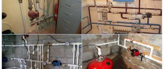
How to choose a circulation pump for heating a private house
The characteristics of any equipment are selected taking into account the conditions of its future operation. How to choose a pump for heating a private house? You can use reference tables that provide the necessary information depending on the square footage of the building. If this option does not suit you, it is worth performing a calculation that will allow you to obtain more accurate values.
Choosing a pump is quite difficult
Pump performance calculation
Pump performance can be calculated using the following formula:
G = M / ΔT × Ct, where:
- M is the power of the boiler that will be used to heat the house, W;
- ΔТ – temperature difference in the heating circuit;
- St – coefficient depending on the specific heat capacity of the coolant.
The boiler power can be found using the formula
The boiler power can be determined based on the fact that for each m² of a cottage or country house, 100 W of power is required, for multi-apartment buildings - 70 W. If there is additional thermal insulation of the external walls, the power is obtained by multiplying 50 kW by the square footage of the house. For cold regions, the calculated value for private houses is increased to 175 W, for multi-storey houses - to 101 W.
When calculating the boiler power, heat loss is taken into account
If calculating the performance of a circulation pump seems too time-consuming, we suggest using a calculator. By selecting the required positions and entering the missing data, you can obtain the desired value.
Circulation pump performance calculator
Device pressure
This parameter determines whether the pump can overcome the force created by the hydraulic resistance of the heating system. If the vertical rise is compensated by the force created in the descending sections of the circuit, then pipes, valves, heat exchangers and other elements create significant resistance. This greatly complicates the calculation procedure.
The pressure of the circulation pump is determined by multiplying the length of the heating circuit by the resistivity of the pipe and a coefficient depending on the number of shut-off valves, thermostats and other elements of the system.
The device pressure must be sufficient
We invite our dear readers to use a calculator specially developed by our team.
Circulation pump pressure calculator
Calculation of the power of the circulation pump for the heating system
For a larger calculation of the circulation pump for a heating system, you can use the following formula:
N = Nk / DT, where
- N – desired value;
- Nк – power of the boiler used for heating the house;
- DT – temperature difference in the forward and return circuits. In most systems it does not exceed 15°C.
Power depends on the temperature difference between the forward and return circuits
What else to pay attention to
When choosing a suitable model, you should also pay attention to the occupancy of the circulation pump. To periodically turn on the equipment in winter, an inexpensive model with low power is sufficient. In this case, the pump will perform an auxiliary function
If the pipeline is long without a circulation pump, the coolant will move slowly. Such a system will require a powerful model that allows continuous operation.
In this case, the pump will perform an auxiliary function. If the pipeline is long without a circulation pump, the coolant will move slowly. Such a system will require a powerful model that allows continuous operation.
Manufacturers offer units whose design allows you to change the speed of their operation. In most cases, we are talking about three-stage adjustment. The user can select the optimal operating mode of the heating system depending on weather conditions. Some models have an automatic power control system.
When choosing, you should also pay attention to:
- maximum pressure in the system. In private homes it rarely exceeds 4 atm (under normal operating conditions - about 2 atm);
- body material. Cast iron is preferred. Products with a body made of heat-resistant plastic will cost less;
- connecting dimensions. An adapter may be required;
- presence and type of protection. Protection against overheating is especially important. With it, the service life of the pump increases significantly.
Frequency of inclusion is an important criterion when choosing
What to consider
Correspondence between casing diameters and pump diameters
When ensuring continuous water supply to a country house, it is important to accurately determine the parameters of water pumps. If an error is made in calculating the required performance, the water intake equipment will pump out an insufficient amount of water - this will inevitably lead to the need to purchase a new pump, and this will be an additional expense.
When calculating the performance of an electric water pump, it is important to take into account the following parameters of the water main and tank:
Source depth
To determine the flow rate, it is important to know the bottom depth. From a practical point of view, these parameters will allow you to optimally select a pump with the required immersion depth and lift height. Knowledge of the static level of the well
This is the interval between the water table and the surface. Allows you to set the height of the water column, as well as the immersion depth of the pump. This parameter is calculated in the absence of complete water intake and the well being at rest for several hours, or preferably a day. Depending on the season, the parameter changes and falls during the spring flood, so calculations are best carried out in the summer in dry and warm weather. Dynamic level - the interval between the water mirror and the surface when the equipment is turned on. This parameter allows you to choose the right submersible pump, as it displays the required immersion depth.
Volume of consumption. The calculation is made based on the number of people living in the house, as well as the performance of the autonomous station. Calculated using special plumbing fixtures, as well as when using a water intake calculator for household appliances
It is important to know that consumption volumes should not exceed the flow rate of the well.
The diameter of the well shaft. This indicator affects the size of the selected pump
In shallow and narrow Abyssinian springs it is not possible to install deep pumps; the liquid is lifted by surface units with a water intake pipe lowered into the shaft. The diameter of standard deep-well centrifugal pumps reaches 4 inches. Designed for sources with a diameter of at least 100 mm. Distance from house to well. When making calculations, it is important not to forget to convert vertical meters to horizontal ones. This ratio depends on the pipe material and its diameter, which affects the hydraulic resistance.
Abyssinian wells have a water layer depth of no more than 8 meters; as a result, the suction holes of the equipment are located in the thickness of the water layer. The deeper sandy varieties have a clay or sandy bottom. In the first and second cases, to avoid filter clogging, screw or centrifugal deep-well pumps equipped with special cleaning filters are used.
Submersible pump power and efficiency
The rated efficiency of a centrifugal pump motor for water supply is the ratio of useful power to that consumed. Designation – η. Distribution formula: η = (P2/P1) * 100. The efficiency of an electric motor will never be higher than one (100%) under any circumstances, since a “perpetual motion machine” does not exist, and any drives have losses.
Efficiency is the name given to the ratio of hydraulics to power supplied to the shaft of the downhole device, and their difference indicates losses in the unit. Formula: η = (P4/P3) * 100.
The loss of power in a centrifugal pumping device also results from a number of components, namely:
- Hydraulic;
- Mechanical;
- Volume losses Pvs.
Submersible pumps for summer cottages can be purchased at any specialized store. The total efficiency is the sum of the efficiency of all losses. The efficiency of a device characterizes the degree of design perfection in terms of mechanics and hydraulics.