rated thermal power" in other dictionaries: rated thermal power
—
The value of
total
power
,
power
per unit length or unit surface area of the electric heater at
rated
values of voltage, temperature and length, expressed in W/m or W/m2.”>
Skip to content
The rated power of the boiler is the main thermal characteristic of the boiler and is expressed in different measurement systems used in the Russian Federation, in kW (mW) or Mcal (Gcal) with their following ratio - 1 Gcal = 1.163 MW.
4.4. Steel hot water boilers of the KV-TSi series KV-TSV
Hot water boilers of the KV-TS series with a layered method of burning solid fuel are produced with a heating capacity of 4; 6.5; 10; 20; thirty; 50 Gcal/h (4.7; 7.5; 11.7; 23.4; 35 and 58.5 MW). Boilers of this series are intended for installation at thermal power plants, in industrial heating and heating boiler houses. Water heating boilers of the KV-TSV series differ from boilers of the KV-TS series only in the presence of an air heater.
All hot water boilers of both these series have combustion screens made of pipes with a diameter of 60 x 3 mm. Convective bags in them are made from pipes with a diameter of 28 x 3 mm. The boilers are equipped with chain return grates with pneumomechanical fuel throwers.
Hot water boilers KV-TS-4 and -6.5 have a convective shaft (Fig. 4.3) with a heating surface and a combustion chamber
Rice. 4.3. Water heating boilers KV-TS-4 and -6.5 :
1 - window for the exit of combustion products from the combustion chamber; 2 - convective shaft with heating surface; 3 - nozzle for returning fuel carryover to the chain grid; 4 - slag bunker; 5 - reverse chain grille; 6 — pneumomechanical fuel thrower; 7 — fuel bunker; 8 - combustion chamber
camera; GHG - combustion products
Fuel (coal) from the hopper 7 is supplied to the return chain grid 5 by means of a pneumo-mechanical spreader. Air for fuel combustion is supplied by a fan into the ducts, through which it is sectioned and supplied under the chain grate. The fuel combustion products from the combustion chamber enter the convective shaft through the upper openings in the rear wall of the combustion chamber (windows). The heat of the GHG is perceived by convective heating surfaces in convective shaft 2, and cooled GHGs are removed from the boiler through a gas duct located in the lower part of the convective shaft. With the GHG flow Fuel is partially carried away from the combustion chamber; to catch it, a special fan is installed in the convection shaft bunker, which returns the carried away fuel through the nozzles to the combustion chamber onto the chain grate.
equipped with chain return grids 7 of different lengths and two pneumomechanical fuel throwers. In the rear part of the combustion chamber there is an intermediate shielded wall 6, forming an afterburning chamber. The screens of the intermediate wall are made of two rows. The side walls of the combustion chamber, as well as the convection shaft, have lightweight lining. The front wall of the combustion chamber is not shielded and has heavy lining.
The front and rear walls of the convection shaft are shielded. The front wall of the convective shaft, which is also the rear wall of the combustion chamber, is made in the form of an all-welded screen, turning into a four-row scallop at the bottom. The side walls of the convective shaft are closed with vertical screens made of pipes with a diameter of 83 3.5 mm.
Combustion products enter the convective shaft from below and pass through the festoon. The shaft contains packages of convective heating surfaces made in the form of horizontal screens. Collected fines and unburned fuel particles are collected in ash bins under the convective shaft and, through the entrainment return system, are thrown into the combustion chamber through pipeline 5. In the front part of the return chain grate 7 there is a slag hopper, where slag is dumped from the grate.
The supply of network water to the boiler is carried out through the lower collector of the left side screen, and the output of hot water is through the lower left collector of the convective shaft.
For burning wet brown coals, boilers of the KB-TS series can be supplied with air heaters that provide air heating to 200...220 °C.
The water heating boiler K.V-TS-50 has a screened combustion chamber (Fig. 4.5), a chain return grate to which fuel is supplied by four pneumo-mechanical throwers. The rear screen of the combustion chamber at the entrance to the rotary chamber is opened into a four-row festoon. The walls and slopes of the rotary chamber, and Also, the rear wall of the convective shaft is shielded with pipes with a diameter of 60 x 3 mm. Convective heating surfaces are made in the form of U-shaped screens made of pipes with a diameter of 28 x 3 mm, which are welded to vertical pipes with a diameter of 83 x 3.5 mm, forming screens for the side walls of the convective shaft.
Behind the boiler there is a two-pass tubular air heater in the form of two cubes made of pipes with a diameter of 40 x 1.5 mm. The boiler is equipped with a fan 7 and devices for returning fuel carryover from the ash bins under the convective shaft and under the air heater to the grate. Secondary sharp blast is carried out through nozzles located on the rear wall of the firebox using a fan. The slag produced by burning fuel is dumped into the mine. To clean convective heating surfaces, a shot cleaning device is provided (shot cleaning unit 5).
Formulas for calculating heat loss
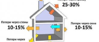
These formulas can be used to calculate heat loss not only in a private house, but also in an apartment. Before starting calculations, it is necessary to draw a floor plan, note the location of the walls relative to the cardinal directions, designate windows, doorways, and also calculate the dimensions of each wall, window and doorway.
To determine heat losses, it is necessary to know the structure of the wall, as well as the thickness of the materials used. The calculations take into account masonry and insulation
When calculating heat loss, two formulas are used - using the first, the value of the thermal resistance of enclosing structures is determined, and using the second, heat loss is determined.
To determine thermal resistance, use the expression:
R = B/K
Here:
- R – the value of thermal resistance of enclosing structures, measured in (m2*K)/W.
- K is the thermal conductivity coefficient of the material from which the enclosing structure is made, measured in W/(m*K).
- B is the thickness of the material, recorded in meters.
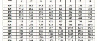
The thermal conductivity coefficient K is a tabular parameter, thickness B is taken from the technical plan of the house.
The thermal conductivity coefficient is a tabular value, it depends on the density and composition of the material, it may differ from the tabulated one, so it is important to read the technical documentation for the material (+)
The basic formula for calculating heat loss is also used:
Q = L × S × dT/R
In the expression:
- Q – heat loss, measured in W.
- S – area of enclosing structures (walls, floors, ceilings).
- dT – the difference between the desired indoor and outdoor temperatures, measured and recorded in C.
- R is the value of the thermal resistance of the structure, m2•C/W, which is found using the formula above.
- L – coefficient depending on the orientation of the walls relative to the cardinal points.
Having the necessary information at hand, you can manually calculate the heat loss of a particular building.
Operating rules
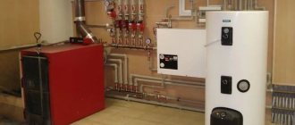
You can avoid a hot water boiler accident by following safety precautions during operation.
The service life of the boiler depends on the quality of its manufacture, the solutions used in the assembly and compliance with operating standards. Installation of the device must be carried out in strict accordance with the technical description of the product and the drawing.
Using the device requires compliance with the following rules:
- use only those types of fuel that are listed in the instructions for the device;
- when using solid fuel devices, have containers for filling extracted ash;
- the firebox door must be kept closed at all times;
- ensure that the temperature and pressure established by the regulations are maintained in the circuit;
- the room where the boiler is located must be protected from access by unauthorized persons;
- pressure gauges and thermometers must be checked at least once every 12 months;
- safety valves must be checked and purged before each boiler start-up;
- Regular cleaning of the chimney is required, even if the stove consumes natural gas;
- Having heard the indicator signal about a system malfunction, you need to act quickly, in strict accordance with the emergency stop instructions.
Boiler power calculation
When calculating the boiler power, it is necessary to use a safety factor of 1.2. That is, the power will be equal to:
W = Q × k
Here:
- Q is the heat loss of the building.
- k is the safety factor.
In our example, we substitute Q = 9237 W and calculate the required boiler power.
W=10489×1.2=12587 W.
Taking into account the safety factor, the required boiler power to heat a house of 120 m2 is approximately 13 kW.
Conclusions and useful video on the topic
Video instruction: how to calculate heat loss at home and boiler power using the Valtec program.
Competent calculation of heat loss and power of a gas boiler using formulas or software methods allows you to determine with high accuracy the necessary equipment parameters, which makes it possible to eliminate unreasonable fuel costs.
Please write comments in the block form below. Tell us how you calculated heat losses before purchasing heating equipment for your own dacha or country house. Ask questions, share information and photographs on the topic.