Installation of a heating system is impossible without preliminary calculations. The information obtained must be as accurate as possible, so air heating calculations are carried out by experts using specialized programs, taking into account the nuances of the design.
You can calculate the air heating system (hereinafter referred to as the air heating system) yourself, having basic knowledge of mathematics and physics.
In this material we will tell you how to calculate the level of heat loss at home and the heat loss system. To make everything as clear as possible, specific examples of calculations will be given.
How to choose the cross-section of the air duct?
The ventilation system, as is known, can be ducted or ductless.
In the first case, you need to choose the right channel cross-section. If a decision is made to install structures with a rectangular cross-section, then the ratio of its length and width should approach 3:1. The length and width of the cross-section of ducted air ducts with a rectangular configuration should be in a ratio of three to one to reduce the amount of noise
The standard speed of movement of air masses along the main ventilation duct should be about five meters per second, and on branches - up to three meters per second. This will ensure the system operates with minimal noise. The speed of air movement largely depends on the cross-sectional area of the duct.
To select the dimensions of the structure, you can use special calculation tables. In such a table, you need to select the air exchange volume on the left, for example, 400 cubic meters per hour, and select the speed value at the top - five meters per second.
Then you need to find the intersection of the horizontal line for air exchange with the vertical line for speed.
Using this diagram, the cross-section of air ducts for a duct ventilation system is calculated. The speed of movement in the main canal should not exceed 5 m/sec
From this intersection, draw a line down to a curve from which a suitable section can be determined. For a rectangular duct this will be the area, and for a round duct this will be the diameter in millimeters. First, calculations are made for the main air duct, and then for the branches.
Thus, calculations are made if only one exhaust duct is planned in the house. If it is intended to install several exhaust ducts, then the total volume of the exhaust duct must be divided by the number of ducts, and then calculations must be made according to the stated principle.
This table allows you to select the cross-section of the air duct for duct ventilation, taking into account the volume and speed of movement of air masses
In addition, there are specialized calculation programs that can be used to perform such calculations. For apartments and residential buildings, such programs can be even more convenient, since they give a more accurate result.
Normal air exchange is influenced by such a phenomenon as reverse draft, the specifics of which and ways to combat it will be introduced in the article we recommend.
The cold season of the year is HP.
1. When air conditioning during the cold season - HP, the optimal parameters of the internal air in the working area of the room are initially taken:
tB = 20 ÷ 22ºC; φВ = 30 ÷ 55%.
2. Initially, we plot points on the Jd diagram using two known parameters of moist air (see Figure 8):
- outside air (•) Н tН = — 28ºC; JH = - 27.3 kJ/kg;
- internal air (•) В tВ = 22ºC; φВ = 30% with minimum relative humidity;
- internal air (•) B1 tB1 = 22ºC; φВ1 = 55% with maximum relative humidity.
If there is excess heat in the room, it is advisable to take the upper temperature parameter of the internal air in the room from the zone of optimal parameters.
3. We compile the heat balance of the room for the cold season of the year - HP:
by sensible heat ∑QХПЯ by total heat ∑QХПЯ
4. We calculate the amount of moisture entering the room
∑W
5. Determine the thermal intensity of the room using the formula:
where: V is the volume of the room, m3.
6. Based on the magnitude of thermal stress, we find the gradient of temperature increase along the height of the room.
Air temperature gradient along the height of public and civil buildings.
| Thermal intensity of the room QЯ/Vroom. | grad t, °C | |
| kJ/m3 | W/m3 | |
| More than 80 | More than 23 | 0,8 ÷ 1,5 |
| 40 ÷ 80 | 10 ÷ 23 | 0,3 ÷ 1,2 |
| Less than 40 | Less than 10 | 0 ÷ 0,5 |
and calculate the temperature of the removed air
tY = tB + grad t(H – hр.з.), ºС
where: H - room height, m; hр.з. — height of the working area, m.
7. To assimilate excess heat and moisture in the room, the supply air temperature - tП, is taken to be 4 ÷ 5ºС lower than the internal air temperature - tB, in the working area of the room.
8. Determine the numerical value of the heat-humidity ratio
9. On the Jd diagram, we connect the point 0.0°C of the temperature scale with a straight line with the numerical value of the heat-humidity ratio (for our example, we take the numerical value of the heat-humidity ratio to be 5,800).
10. On the Jd diagram we draw the supply isotherm - tП, with a numerical value
tP = tB - 5, °C.
11. On the Jd diagram we draw an isotherm of the outgoing air with the numerical value of the outgoing air - tУ, found in point 6.
12. Through the points of internal air - (•) B, (•) B1, we draw lines that are parallel to the line of heat-humidity ratio.
13. The intersection of these lines, which will be called process rays
with isotherms of supply and exhaust air - tП and tУ will determine the supply air points on the Jd diagram - (•) P, (•) P1 and the points of exhaust air - (•) U, (•) U1.
14. Determine air exchange by total heat
and air exchange to assimilate excess moisture
Air heating technique
Air is a very productive coolant. The most simplified example of an air heating system is a conventional fan heater. This mechanism can warm up a small room in a few minutes. But to organize air heating of a country house, the use of more serious equipment is required.
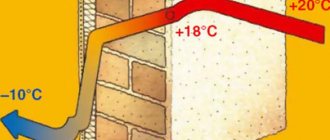
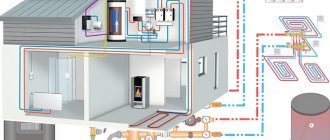
The technology for operating a heating system using air is as follows. The heat generator heats air masses that enter the building through a pipe system. Here, air currents mix with the air space of the rooms, thereby increasing the temperature. The cooled air rushes down, from where it enters a special pipeline and is sent through it again to the heat generator for heating.
This heating system for a private home involves the use of specially designed thermoregulation, in which the air is first heated to the required temperature, and then transfers its heat to the room, warming all objects around. Heating of air masses occurs without intermediaries in the form of a system of pipes and batteries, so there is simply no irrational heat loss here.
Such heating is usually used for frame structures, which are widespread in Canada, hence the name of the technology. The fact is that frame buildings, unlike brick buildings, are not able to effectively retain heat from radiators, and heating with air creates an acceptable microclimate with low financial costs.
How to make air heating with your own hands?
After receiving all the necessary calculations, you can begin preparing for the installation of the chosen system, because it is not so difficult to organize air heating of a private house with your own hands. First you need to draw a diagram of the approximate passage of the air ducts and their connections to each other.
Having drawn up an approximate procedure for connecting the system, it is better to discuss it with professionals, even if you already have personal experience in this matter, so that an outsider can give an objective assessment and find hidden flaws that can lead to vibration, drafts and extraneous noise during operation of the equipment.
An experienced expert can assist in choosing a suitable heat generator model that can ensure the air is heated to the required temperature and does not overheat during intense activity. If the unit is quite large, it is better to allocate a separate extension adjacent to the house for it.
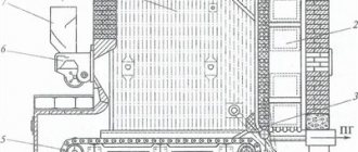
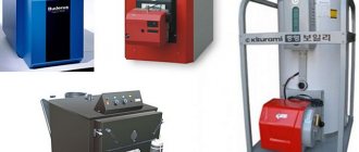
There are two types of thermal generators:
- Stationary. They usually use gas fuel and, due to their impressive dimensions and for safety reasons, should be installed exclusively in separate rooms. They are mainly used for heating huge buildings; they are also often placed in factory workshops.
- Mobile. Convenient for those who have dachas and country cottages; they are more compact than their stationary counterparts. Their combustion chamber is isolated, but to ensure safety, these structures must be located in rooms with a built-in smoke exhaust system. This type is also known as a heater type.
The process of self-installation of air heating equipment consists of several stages:
- Install the boiler and heat exchanger. The first one is almost always installed in the basement. It is prohibited to connect its gas version on your own; this must be agreed upon with the relevant services.
- Make holes in the wall of the room where the heat exchanger is located for the outlet of the air exhaust hose.
- Connect the heat exchanger to the air supply pipe.
- Install a fan under the combustion chamber. Connection to the outside of the return pipe.
- Carry out the wiring of air vents and their fastening. Typically, they are selected with a round cross-section; special brackets need to be selected for it.
- Connect the supply ducts and return air duct and insulate them.
It is relatively easy to equip the system with your own hands, but it is unlikely that you will be able to carry out all the calculations correctly. Possible errors will lead to a decrease in the efficiency of the structure, constant drafts and other unpleasant consequences. Therefore, it is better to get a professionally prepared project and, if desired, implement it yourself.
Air heating of a home is an effective and profitable heating method, which is characterized by greater productivity compared to traditional water and gas systems. An air heating system can significantly improve the quality of life in a private home. This heating option is one of the safest, most economical, extremely durable and reliable systems. Therefore, it is becoming more and more in demand.
Example initial conditions
For a more specific explanation of all the details of the hydraulic calculation, let’s take a specific example of an ordinary living space. We have a classic 2-room apartment in a panel house with a total area of 65.54 m2, which includes two rooms, a kitchen, separate toilet and bathroom, a double corridor, a twin balcony.
After commissioning, we received the following information regarding the readiness of the apartment. The described apartment includes walls made of monolithic reinforced concrete structures treated with putty and primer, profile windows with two-chamber glass, pressed interior doors, ceramic tiles on the bathroom floor.
A typical 9-storey panel house with four entrances. There are 3 apartments on each floor: one 2-room and two 3-room. The apartment is located on the fifth floor
In addition, the presented housing is already equipped with copper wiring, distributors and a separate panel, a gas stove, a bathtub, a washbasin, a toilet, a heated towel rail, and a sink.
And most importantly, the living rooms, bathroom and kitchen already have aluminum heating radiators. The question regarding the pipes and boiler remains open.
Single-pipe heating circuit
From the heating boiler you need to draw a main line representing a branch. After this action, it contains the required number of radiators or batteries. The line, drawn according to the building designs, is connected to the boiler. The method creates coolant circulation inside the pipe, heating the building completely. The circulation of warm water is adjusted individually.
A closed heating scheme for Leningradka is planned. In this process, a single-pipe complex is installed according to the current design of private houses. At the owner's request, the following elements are added:
- Radiator controllers.
- Thermostats.
- Balancing valves.
- Ball valves.
Leningradka regulates the heating of certain radiators.
Advance paynemt
When planning to do air heating at home with your own hands, it is very important to correctly make all the calculations before starting work. Things to consider:
- Estimated heat loss in each individual room.
- The required power of the heat generator and its type.
- How much air will be heated?
- Calculation of the area of air ducts, their length and diameter.
- Determine possible air pressure losses.
- Calculate the correct speed of air movement in the room so that there are no drafts and at the same time, the circulation of air masses in the house effectively occurs and it is evenly heated.
A mistake made at the air system planning stage will result in lost time and serious amounts of money if the heating does not work properly and everything has to be redone.
The engineer will offer several options for the air heating system. All that remains is to choose the appropriate one.
Only after making accurate calculations and drawing up a project, do they begin to purchase a heating device and all the necessary materials.
Feasibility study of the project
The choice of one or another design solution is, as a rule, a multifactorial task. In all cases, there are a large number of possible options for solving the problem, since any TG and V system is characterized by many variables (a set of system equipment, its various parameters, pipeline sections, materials from which they are made, etc.).
In this section we compare 2 types of radiators: Rifar Monolit 350 and Sira RS 300.
To determine the cost of the radiator, we will perform their thermal calculation in order to clarify the number of sections. Calculation of the Rifar Monolit 350 radiator is given in section 5.2.
An example of calculating heat loss at home
The house in question is located in the city of Kostroma, where the temperature outside during the coldest five-day period reaches -31 degrees, the ground temperature is +5°C. The desired room temperature is +22°C.
We will consider a house with the following dimensions:
- width - 6.78 m;
- length - 8.04 m;
- height - 2.8 m.
The values will be used to calculate the area of the enclosing elements.
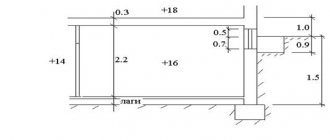
For calculations, it is most convenient to draw a house plan on paper, indicating on it the width, length, height of the building, the location of windows and doors, their dimensions
The walls of the building consist of:
- aerated concrete with thickness B=0.21 m, thermal conductivity coefficient k=2.87;
- foam plastic B=0.05 m, k=1.678;
- facing brick B=0.09 m, k=2.26.
When determining k, you should use information from tables, or better yet, information from a technical data sheet, since the composition of materials from different manufacturers may differ and, therefore, have different characteristics.
Reinforced concrete has the highest thermal conductivity, mineral wool slabs have the lowest, so they are most effectively used in the construction of warm houses
The floor of the house consists of the following layers:
- sand, B=0.10 m, k=0.58;
- crushed stone, B=0.10 m, k=0.13;
- concrete, B=0.20 m, k=1.1;
- ecowool insulation, B=0.20 m, k=0.043;
- reinforced screed, B=0.30 m k=0.93.
In the above house plan, the floor has the same structure throughout the entire area; there is no basement.
The ceiling consists of:
- mineral wool, B=0.10 m, k=0.05;
- plasterboard, B=0.025 m, k= 0.21;
- pine panels, B=0.05 m, k=0.35.
The ceiling has no access to the attic.
There are only 8 windows in the house, all of them are double-chamber with K-glass, argon, D = 0.6. Six windows have dimensions of 1.2x1.5 m, one - 1.2x2 m, one - 0.3x0.5 m. The doors have dimensions of 1x2.2 m, the D value according to the passport is 0.36.
Technical characteristics and cost of Calorex Delta
| Model Calorex Delta | 1 | 2 | 4 | 6 | 8 | 10 | 12 | 14 | 16 | |
| Cost of model A 230 V | Euro | on request | on request | on request | on request | |||||
| Cost of model B 400 V | Euro | on request | on request | on request | on request | on request | on request | on request | on request | on request |
| Compressor | ||||||||||
| Nominal power consumption | kW | 2 | 2,6 | 2,6 | 3,4 | 4,1 | 5,2 | 6,3 | 7,8 | 13,3 |
| Startup: 1st phase | A | 56 | 76 | 76 | 100 | N/A | N/A | N/A | N/A | N/A |
| Operation: 1 phase | A | 8,1 | 12,4 | 12,4 | 16,6 | N/A | N/A | N/A | N/A | N/A |
| Soft start: 1st phase | A | 27 | 31 | 31 | 34 | N/A | N/A | N/A | N/A | N/A |
| Launch: 3 phase | A | 38 | 42 | 42 | 48 | 64 | 75 | 101 | 167 | 198 |
| Operation: 3 phase | A | 3,9 | 4,7 | 4,7 | 7,3 | 6,3 | 7,4 | 11,5 | 20,7 | 24,9 |
| Soft start: phase 3 | A | 15 | 16 | 16 | 17 | 28 | 30 | 34 | 39 | 41 |
| Main fan | ||||||||||
| Airflow | m³/hour | 2 500 | 2 600 | 3 000 | 4 000 | 5 000 | 6 000 | 7 000 | 10 000 | 12 000 |
| Maximum external static pressure | Pa | 147 | 147 | 196 | 196 | 196 | 245 | 245 | 245 | 294 |
| FLA: 1 phase | A | 4,6 | 4,6 | 3,9 | 6,4 | N/A | N/A | N/A | N/A | N/A |
| FLA: 3 phase | A | N/A | N/A | 1,6 | 2,6 | 3,7 | 3,7 | 3,7 | 7,4 | 11 |
| Exhaust fan | ||||||||||
| Air flow (summer) | m³/hour | 1 200 | 1 300 | 1 500 | 2 000 | 2 500 | 3 000 | 3 500 | 6 700 | 8 000 |
| Air flow (winter) | m³/hour | 600 | 650 | 750 | 1 000 | 1 250 | 1 500 | 1 750 | 3 350 | 4 000 |
| Air flow (during non-use) | m³/hour | 120 | 130 | 150 | 200 | 250 | 300 | 350 | 670 | 850 |
| Maximum external static pressure | Pa | 49 | 49 | 98 | 98 | 98 | 147 | 147 | 147 | 147 |
| FLA: 1 phase | A | 1,6 | 1,6 | 2,9 | 4,8 | N/A | N/A | N/A | N/A | N/A |
| FLA: 3 phase | A | N/A | N/A | 1,2 | 2,1 | 2,1 | 2,6 | 2,6 | 4,2 | 7,4 |
| Dehumidification performance | ||||||||||
| Using a heat pump | l/hour | 4,5 | 5,5 | 6 | 8 | 10 | 12 | 14 | 28 | 30 |
| Total @ 18°C dew point (summer) | l/hour | 6,5 | 7,3 | 9 | 12 | 15 | 18 | 21 | 41 | 48 |
| Total @ 7°C dew point (winter) | l/hour | 9,5 | 10,7 | 12,1 | 16,1 | 20,1 | 24,2 | 28,2 | 55 | 60,5 |
| VDI 2089 | l/hour | 7,6 | 8,2 | 9,5 | 12,6 | 15,8 | 19 | 22,2 | 42,5 | 51,4 |
| Total DH + VDI 2089 @ 12.5°C dew point (summer) | l/hour | 9,8 | 10,9 | 12,5 | 16,6 | 20,8 | 25 | 29,2 | 56,5 | 62,4 |
| Air heating | ||||||||||
| Via heat pump (mode A) | kW | 1,3 | 1,5 | 1,4 | 1,5 | 1,6 | 2 | 2,5 | 6 | 7 |
| Via heat pump (mode B) | kW | 3,8 | 4,9 | 5,1 | 6,6 | 8 | 10 | 12,1 | 30 | 35 |
| Via LPHW @ 80°C (water heater) | kW | 20 | 22 | 25 | 30 | 35 | 38 | 42 | 85 | 90 |
| Total | kW | 21,3/23,8 | 23,5/26,9 | 26,4/30,1 | 31,5/36,6 | 36,6/43 | 40/48 | 44,5/54,1 | 91/115 | 97/125 |
| Water heating | ||||||||||
| Via heat pump (mode A) | kW | 4 | 5,5 | 5,8 | 8 | 10 | 12,5 | 15 | 35 | 43 |
| Via heat pump (mode B) | kW | 1,7 | 2,2 | 2,3 | 3 | 3,7 | 4,6 | 5,5 | 12 | 14 |
| Via LPHW @ 80°C (water heater) | kW | 10 | 10 | 10 | 15 | 15 | 30 | 30 | 65 | 65 |
| Total: | kW | 14/11,7 | 15,5/12,2 | 15,8/12,3 | 23/18 | 25/18,7 | 42,5/34,6 | 45/35,5 | 100/77 | 108/79 |
| Flow rate | l/min | 68 | 68 | 68 | 110 | 110 | 140 | 140 | 100 | 100 |
| Maximum working pressure Delta | bar | 3,5 | 3,5 | 3,5 | 3,5 | 3,5 | 3,5 | 3,5 | 3,5 | 3,5 |
| Cooling | A/B mode | A/B mode | A/B mode | A/B mode | A/B mode | A/B mode | A/B mode | A/B mode | A/B mode | |
| Cooling performance (perceived) | kW | -2/N/A | -2.5/N/A | -2,94 | -3,85 | -4,7 | -5,9 | -7,1 | -13 | -15 |
| Performance (total) | kW | -3/N/A | -4/N/A | -4,2 | -5,5 | -6,7 | -8,4 | -10,1 | -23 | -28 |
| Recommended coolant power | kW | 30 | 32 | 35 | 45 | 50 | 65 | 70 | 1 50 | 150 |
| Flow rate | l/min | 25 | 25 | 30 | 37 | 42 | 64 | 64 | 115 | 115 |
| Maximum working pressure Delta | bar | 6 | 6 | 6 | 6 | 6 | 6 | 6 | 6 | 6 |
| Pressure drop @ design flow | bar | 0,2 | 0,2 | 0,25 | 0,25 | 0,3 | 0,32 | 0,32 | 0,35 | 0,4 |
| Electrical data | ||||||||||
| Total power consumption (nominal) | kW | 3,18 | 3,84 | 3,94 | 5,12 | 6,25 | 7,8 | 9,35 | 15 | 18 |
| Min. current (max. at FLA) 1 phase | A | 16 | 20 | 20 | 31 | N/A | N/A | N/A | N/A | N/A |
| Min. current (max. at FLA) 3 phase | A | 11 | 12 | 9 | 13 | 13 | 15 | 20 | 35 | 48 |
| Max. power fuse 1 phase | A | 25 | 32 | 33 | 48 | N/A | N/A | N/A | N/A | N/A |
| Max. power fuse 3 phase | A | 17 | 19 | 14 | 18 | 21 | 24 | 30 | 50 | 60 |
| Total information | ||||||||||
| Height | 1 735 | 1 910 | 1 955 | 2 120 | ||||||
| Size Width | mm | 1 530 | 1 620 | 1 620 | 2 638 | |||||
| Depth | 655 | 705 | 855 | 1 122 | ||||||
| Installation weight approximate (without packaging) | kg | 300 | 310 | 350 | 360 | 370 | 410 | 460 | 954 | 1 020 |
| To select equipment, please contact | ||||||||||
| Maximum recommended pool size | ||||||||||
| Swimming pool in an individual house | m² | 50 | 65 | 70 | 90 | 110 | 130 | 160 | 300 | 360 |
| Swimming pool of a small holiday home | m² | 45 | 55 | 60 | 80 | 100 | 120 | 140 | 220 | 265 |
| Public pool | m² | 40 | 50 | 55 | 70 | 90 | 110 | 130 | 200 | 240 |
Additional system elements
It is irrational to use an air system only for heating; it can be used to make a universal device for creating a microclimate in the house. To do this, a unit for air cooling and an air conditioning unit are built into the device.
This system provides heating in winter and cooling in summer, maintaining a pleasant temperature inside the house regardless of the weather outside. In addition, the system is supplemented with some other useful equipment:
- Electronic filter. It consists of removable cassettes that purify the incoming air by ionizing it. The filter plates trap micro-dust particles. The cassettes are easily removed and cleaned by rinsing under running water.
- Humidifier. It is an evaporation unit with flowing water. Hot air passing through this block promotes active evaporation of moisture. This way the air is actively humidified.
- The required level of humidification is controlled by a special humidity sensor with a regulator.
- UV lamp for air purification. Ultraviolet light disinfects pathogenic bacteria in the air.
- Thermostat with programmability. Controls the entire heating and cooling system. Connects to the Internet, so you can control the temperature in your home from anywhere. Has 4 programmed modes.
- Electronic ventilation control unit. Allows you to control the ventilation system autonomously or completely turn it off if necessary.
WATCH THE VIDEO
A properly designed and well-made home air heating system will delight residents with a pleasant microclimate for many years.
The first method is classic (see figure
1. Outdoor air treatment processes:
- heating of outside air in the 1st heating air heater;
- adiabatic cycle humidification;
- heating in the 2nd heating air heater.
2. From the point with the parameters of the outside air - (•) H we draw a line of constant moisture content - dH = const.
This line characterizes the process of heating the outside air in the 1st heating air heater. The final parameters of the outside air after it has been heated will be determined in paragraph 8.
3. From the point with the parameters of the supply air - (•) P, draw a line of constant moisture content dP = const until it intersects with the line of relative humidity φ = 90% (this relative humidity is stably provided by the irrigation chamber with adiabatic humidification).
We get point - (•) O with the parameters of humidified and cooled supply air.
4. Through the point - (•) O we draw the isotherm line - tO = const until it intersects with the temperature scale.
The temperature value at point - (•) O is close to 0°C. Therefore, fog may form in the irrigation chamber.
5. Consequently, in the zone of optimal internal air parameters in the room, it is necessary to select another point of internal air - (•) B1 with the same temperature - tB1 = 22°C, but with higher relative humidity - φB1 = 55%.
In our case, point - (•) B1 was taken with the highest relative humidity from the zone of optimal parameters. If necessary, it is possible to accept intermediate relative humidity from the zone of optimal parameters.
6. Similar to point 3. From the point with the parameters of the supply air - (•) P1, draw a line of constant moisture content dP1 = const until it intersects with the line of relative humidity φ = 90%.
We get point - (•) O1 with the parameters of humidified and cooled supply air.
7. Through the point - (•) O1, draw the isotherm line - tO1 = const until it intersects with the temperature scale and read the numerical value of the temperature of the humidified and cooled air.
Important note!
The minimum value of the final air temperature during adiabatic humidification should be within 5 ÷ 7 ° C.
8. From the point with the parameters of the supply air - (•) P1, draw a line of constant heat content - JP1 = const until it intersects with the line of constant moisture content of the outside air - point (•) H - dH = const.
We get point - (•) K1 with the parameters of heated outside air in the 1st heating air heater.
9. External air processing processes on the Jd diagram will be depicted by the following lines:
- line NK1 - process of heating the supply air in the 1st heating air heater;
- line K1O1 - the process of humidifying and cooling heated air in the irrigation chamber;
- line O1P1 - the process of heating humidified and cooled supply air in the 2nd heating air heater.
10. Treated external supply air with parameters at point - (•) P1 enters the room and assimilates excess heat and moisture along the process path - line P1B1. Due to the increase in air temperature along the height of the room - grad t. Air parameters change. The process of changing parameters occurs along the process beam to the point of exhaust air - (•) U1.
11. The required amount of supply air to assimilate excess heat and moisture in the room is determined by the formula
12. Required amount of heat to heat the outside air in the 1st heating air heater
Q1 = GΔJ(JK1 - JH) = GΔJ(tK1 - tH), kJ/h
13. The required amount of moisture to humidify the supply air in the irrigation chamber
W = GΔJ(dO1 - dK1), g/h
14. Required amount of heat to heat humidified and cooled supply air in the 2nd heating air heater
Q2 = GΔJ(JP1 - JO1) = GΔJ x C(tP1 - tO1), kJ/h
The value of the specific heat capacity of air C is taken to be:
C = 1.005 kJ/(kg × °C).
To obtain the thermal power of the 1st and 2nd heating heaters in kW, it is necessary to divide the values of Q1 and Q2 in kJ/h by 3600.
Schematic diagram of supply air treatment during the cold season - HP, for the 1st method - classic, see Figure 9.
Air heating of industrial premises
Through the air duct system, heat is distributed throughout the production workshop.
The air heating system at each specific industrial enterprise can be used as the main one or as an auxiliary one. In any case, installing air heating in a workshop is cheaper than water heating, since there is no need to install expensive boilers for heating production premises, lay pipelines and install radiators.
Advantages of an air heating system for a production facility:
- saving work area area;
- energy efficient consumption of resources;
- simultaneous heating and air purification;
- uniform heating of the room;
- safety for the well-being of workers;
- no risk of leaks and freezing of the system.
Air heating of a production facility can be:
- central - with a single heating unit and an extensive network of air ducts through which heated air is distributed throughout the workshop;
- local - air heaters (air heating units, heat guns, air heat curtains) are located directly in the room.
In a centralized air heating system, to reduce energy costs, a recuperator is used, which partially uses the heat of internal air to heat fresh air coming from outside. Local systems do not recuperate; they only warm the internal air, but do not provide an influx of external air. Wall-ceiling air heating units can be used to heat individual workplaces, as well as for drying any materials and surfaces.
By giving preference to air heating of industrial premises, enterprise managers achieve savings by significantly reducing capital costs.
Fourth method (see Figure 14).
The use of cellular humidifiers makes it possible to solve the issue of air humidification in the most optimal way from the point of view of energy consumption. By setting the frontal speed of movement Vf = 2.3 m/sec of the supply air in the cellular humidifier, you can achieve the relative humidity of the supply air:
- with a honeycomb nozzle depth of 100mm - φ = 45%;
- with a honeycomb nozzle depth of 200mm - φ = 65%;
- with a honeycomb nozzle depth of 300mm - φ = 90%.
1. We select the internal air parameters from the zone of optimal parameters:
- temperature – maximum tB = 22°C;
- relative humidity – minimum φВ = 30%.
2. Using two known parameters of internal air, we find a point on the Jd diagram - (•) B.
3. The supply air temperature is taken to be 5°C less than the internal air temperature
tP = tB - 5, °C.
On the Jd diagram we draw the supply air isotherm - tP.
4. Through the point with the parameters of the internal air - (•) B we draw a process ray with a numerical value of the heat-humidity ratio
ε = 5,800 kJ/kg H2O
until it intersects with the supply air isotherm - tП.
We get a point with the parameters of the supply air - (•) P.
5. From the point with the parameters of the outside air - (•) H we draw a line of constant moisture content - dH = const.
6. From the point with the parameters of the supply air - (•) P, draw a line of constant heat content - JP = const until it intersects with the lines:
relative humidity φ = 65%.
We get a point with the parameters of humidified and cooled supply air - (•) O.
constant moisture content of outside air - dН = const.
We get a point with the parameters of the supply air heated in the heater - (•) K.
7. We pass part of the heated supply air through the cellular humidifier, and pass the remaining part of the air through the bypass, bypassing the cellular humidifier.
8. Mix humidified and cooled air with parameters at point - (•) O with air passing through the bypass, with parameters at point - (•) K in such proportions that the mixture point - (•) C is aligned with the supply air point - (•) P:
- line KO - total amount of supply air - GP;
- line KS - the amount of humidified and cooled air - GO;
- CO line - the amount of air passing through the bypass - GP - GO.
9. External air processing processes on the Jd diagram will be depicted by the following lines:
- line NK - the process of heating the supply air in the air heater;
- line KS - the process of humidifying and cooling part of the heated air in a cellular humidifier;
- CO line - bypassing heated air, bypassing the cellular humidifier;
- line KO - mixing of humidified and cooled air with heated air.
10. Treated external supply air with parameters at point - (•) P enters the room and assimilates excess heat and moisture along the process path - the PV line. Due to the increase in air temperature along the height of the room - grad t. Air parameters change. The process of changing parameters occurs along the process beam to the point of outgoing air - (•) U.
11. The amount of air passing through the irrigation chamber can be determined by the ratio of the segments
12. The required amount of moisture to humidify the supply air in the irrigation chamber
Schematic diagram of supply air treatment during the cold season - HP, for the 4th method, see Figure 15.
Stage three: linking branches
When all the necessary calculations have been carried out, it is necessary to link several branches. If the system serves one level, then branches not included in the main line are linked. The calculation is carried out in the same order as for the main line. The results are entered into the table. In multi-storey buildings, floor branches at intermediate levels are used for linking.
Linking criteria
Here the values of the sum of losses are compared: pressure along the linked sections with a parallel connected main line. It is necessary that the deviation is no more than 10 percent. If it is determined that the discrepancy is greater, then the linkage can be carried out:
- by selecting the appropriate cross-sectional dimensions of the air ducts;
- by installing diaphragms or throttle valves on the branches.
Sometimes all you need to make such calculations is a calculator and a couple of reference books. If you need to carry out an aerodynamic calculation of the ventilation of large buildings or industrial premises, then you will need an appropriate program. It will allow you to quickly determine the dimensions of sections and pressure losses both in individual sections and in the entire system as a whole.
https://www.youtube.com/watch?v=v6stIpWGDow Video can't be loaded: Design of ventilation systems. (https://www.youtube.com/watch?v=v6stIpWGDow)
The purpose of the aerodynamic calculation is to determine the pressure loss (resistance) to air movement in all elements of the ventilation system - air ducts, their shaped elements, grilles, diffusers, air heaters and others. Knowing the total value of these losses, you can select a fan that can provide the required air flow. There are direct and inverse problems of aerodynamic calculations. The direct problem to be solved when designing newly created ventilation systems is to determine the cross-sectional area of all sections of the system at a given flow rate through them. The inverse problem is to determine the air flow for a given cross-sectional area of operating or reconstructed ventilation systems. In such cases, to achieve the required flow rate, it is enough to change the fan speed or replace it with a different size.
By area F
determine the diameter D
(for a round shape) or height
A
and width
B
(for a rectangular) air duct, m. The resulting values are rounded to the nearest larger standard size, i.e.
D st
,
A st
and
B st
(reference value).
Recalculate the actual cross-sectional area F
fact and speed v fact
.
For a rectangular duct, the so-called equivalent diameter DL = (2A st * B st) / (A st + B st ), m.
Determine the value of the Reynolds similarity criterion
Re = 64100* D st * v fact.
For a rectangular shape
DL = D art.
Friction coefficient
λtr = 0.3164 ⁄ Re-0.25 at Re≤60000, λtr = 0.1266 ⁄ Re-0.167 at Re>60000.
The local resistance coefficient
λm
depends on their type, quantity and is selected from reference books.
Comments:
- Initial data for calculations
- Where to start? Calculation order
The heart of any ventilation system with mechanical airflow is the fan, which creates this flow in the air ducts. The power of the fan directly depends on the pressure that must be created at the outlet, and in order to determine the value of this pressure, it is necessary to calculate the resistance of the entire channel system.
To calculate pressure losses, you need a diagram and dimensions of the air duct and additional equipment.
Where to start?
Diagram of pressure loss for each meter of duct.
Very often you have to deal with fairly simple ventilation schemes, in which there is an air duct of the same diameter and there is no additional equipment. Such circuits are calculated quite simply, but what if the circuit is complex with many branches? According to the method for calculating pressure losses in air ducts, which is set out in many reference publications, it is necessary to determine the longest branch of the system or the branch with the greatest resistance. It is rarely possible to determine resistance by eye, so it is customary to carry out calculations based on the longest branch. After this, using the air flow rates indicated on the diagram, the entire branch is divided into sections according to this criterion. As a rule, costs change after branches (tees) and when dividing it is best to focus on them. There are other options, for example, supply or exhaust grilles built directly into the main air duct. If this is not shown in the diagram, but such a grid is available, you will need to calculate the flow rate after it. Areas are numbered starting from the one furthest from the fan.
What is the difference between solid fuel boilers
In addition to the fact that these heat sources produce thermal energy by burning various types of solid fuel, they have a number of other differences from other heat generators. These differences are precisely a consequence of burning wood; they must be taken as a given and always taken into account when connecting the boiler to a water heating system. The features are as follows:
- High inertia. At the moment, there are no ways to quickly extinguish a solid fuel fire in a combustion chamber.
- Formation of condensation in the firebox. The peculiarity manifests itself when coolant with a low temperature (below 50 ° C) enters the boiler tank.
Note. The phenomenon of inertia is absent only in one type of solid fuel units - pellet boilers. They have a burner into which wood pellets are fed in doses; after the supply is stopped, the flame goes out almost immediately.
The danger of inertia is the possible overheating of the water jacket of the heater, as a result of which the coolant in it boils. Steam is generated, which creates high pressure, rupturing the body of the unit and part of the supply pipeline. As a result, there is a lot of water in the furnace room, a lot of steam and a solid fuel boiler unsuitable for further use.
A similar situation can arise when the heat generator piping is done incorrectly. After all, in fact, the normal operating mode of wood-burning boilers is maximum; it is at this time that the unit reaches its rated efficiency. When the thermostat reacts to the coolant reaching a temperature of 85 °C and closes the air damper, combustion and smoldering in the firebox still continues. The water temperature rises another 2-4 °C, or even more, before its growth stops.
In order to avoid excess pressure and a subsequent accident, an important element is always involved in the piping of a solid fuel boiler - a safety group, which will be discussed in more detail below.
Another unpleasant feature of the unit operating on wood is the appearance of condensation on the inner walls of the firebox due to the passage of not yet heated coolant through the water jacket. This condensate is not God’s dew at all, since it is an aggressive liquid that quickly corrodes the steel walls of the combustion chamber. Then, having mixed with the ash, the condensate turns into a sticky substance that is not so easy to tear off from the surface. The problem is solved by installing a mixing unit in the piping circuit of a solid fuel boiler.
This coating serves as a heat insulator and reduces the efficiency of a solid fuel boiler.
It is too early to breathe a sigh of relief for owners of heat generators with cast iron heat exchangers that are not afraid of corrosion. Another misfortune may await them - the possibility of destruction of cast iron from temperature shock. Imagine that in a private house the electricity was turned off for 20-30 minutes and the circulation pump driving water through the solid fuel boiler stopped. During this time, the water in the radiators has time to cool down, and in the heat exchanger it has time to heat up (due to the same inertia).
Electricity appears, the pump turns on and directs the cooled coolant from the closed heating system into the heated boiler. Due to a sharp temperature change, the heat exchanger experiences a temperature shock, the cast iron section cracks, and water runs onto the floor. It is very difficult to repair; it is not always possible to replace a section. So even in this situation, the mixing unit will prevent an accident, which will be discussed below.
Emergency situations and their consequences are described not with the aim of scaring users of solid fuel boilers or encouraging them to purchase unnecessary elements of piping schemes. The description is based on practical experience, which must always be taken into account. If the heating unit is connected correctly, the likelihood of such consequences is extremely low, almost the same as with heat generators using other types of fuel.
Calculation of water volume and capacity of the expansion tank
To calculate the performance characteristics of the expansion tank, which is mandatory for any closed-type heating system, you will need to understand the phenomenon of increasing the volume of liquid in it. This indicator is assessed taking into account changes in basic operating characteristics, including fluctuations in its temperature. In this case, it varies over a very wide range - from room temperature +20 degrees and up to operating values within 50-80 degrees.
It will be possible to calculate the volume of the expansion tank without unnecessary problems if you use a rough estimate proven in practice. It is based on equipment operating experience, according to which the volume of the expansion tank is approximately one tenth of the total amount of coolant circulating in the system
In this case, all its elements are taken into account, including heating radiators (batteries), as well as the water jacket of the boiler unit. To determine the exact value of the required indicator, you will need to take the passport of the equipment being used and find in it the items relating to the capacity of the batteries and the working tank of the boiler. After determining them, it is not difficult to find excess coolant in the system
To do this, first calculate the cross-sectional area of polypropylene pipes, and then multiply the resulting value by the length of the pipeline. After summing up all branches of the heating system, the figures for radiators and boiler taken from the passport are added to them. One tenth is then deducted from the total amount
Once they are determined, it is not difficult to find excess coolant in the system. To do this, first calculate the cross-sectional area of polypropylene pipes, and then multiply the resulting value by the length of the pipeline. After summing up all branches of the heating system, the figures for radiators and boiler taken from the passport are added to them. One tenth is then subtracted from the total amount.
Do-it-yourself installation recommendations
To lay the main natural circulation lines, it is better to use polypropylene or steel pipes. The reason is the large diameter, polyethylene Ø40 mm and more is too expensive. We make radiator hoses from any convenient material.
An example of installing two-pipe wiring in a garage
How to make the layout correctly and withstand all the slopes:
- Start with markings. Mark the locations for installing batteries, connection points for connections, and routes for highways.
- Mark the routes on the walls with a pencil, starting from the distant batteries. Adjust the amount of inclination using a long building level.
- Move from the outer radiators to the boiler room. When you draw all the routes, you will understand at what level to install the heat generator. The inlet pipe of the unit (for cooled coolant) must be located at the same level or below the return line.
- If the firebox floor level is too high, try moving all the heaters up. Horizontal pipelines will rise next. As a last resort, make a recess under the boiler.
Laying a return line in a furnace room with parallel connection to two boilers
After applying the markings, punch holes in the partitions and cut grooves for the hidden gasket. Then check the routes again, make adjustments and proceed with installation. Follow the same order: first secure the batteries, then lay the pipes towards the combustion chamber. Install an expansion tank with a drain pipe.
The gravity pipeline network is filled without problems; Mayevsky’s taps do not need to be touched. Just slowly pump water through the fill valve at the lowest point, all the air will go into the open tank. If any radiator remains cold after warming up, use a manual air vent.
Application of thermal air curtains
To reduce the volume of air entering the room when opening external gates or doors, special thermal air curtains are used in the cold season.
At other times of the year they can be used as recycling units. It is recommended to use such thermal curtains:
- for external doors or openings in wet rooms;
- at constantly opening openings in the external walls of buildings that are not equipped with vestibules and can be opened more than five times in 40 minutes, or in areas with an estimated air temperature below 15 degrees;
- for external doors of buildings, if they are adjacent to rooms without vestibules that are equipped with air conditioning systems;
- at openings in internal walls or in partitions of industrial premises to avoid the transfer of coolant from one room to another;
- at the gates or doors of air-conditioned rooms with special technological requirements.
An example of calculating air heating for each of the above purposes can serve as a supplement to the feasibility study for installing this type of equipment.
The temperature of the air supplied to the room by thermal curtains is taken to be no higher than 50 degrees at external doors, and no more than 70 degrees at external gates or openings.
When calculating an air heating system, take the following values for the temperature of the mixture entering through external doors or openings (in degrees):
5 - for industrial premises during heavy work and workplaces located no closer than 3 meters to the external walls or 6 meters from the doors; 8 - for heavy types of work for industrial premises; 12 - for moderately heavy work in industrial premises, or in the lobbies of public or administrative buildings. 14 - for light work for industrial premises.
For high-quality heating of the house, the correct location of the heating elements is necessary. Click to enlarge.
Calculation of air heating systems using thermal curtains is carried out for various external conditions.
Air thermal curtains at external doors, openings or gates are calculated taking into account wind pressure.
The coolant flow in such units is determined from the wind speed and outside air temperature at parameters B (at a speed of no more than 5 m per second).
In cases where the wind speed at parameters A is greater than at parameters B, the air heaters should be checked when exposed to parameters A.
The speed of air outflow from cracks or external openings of thermal curtains is taken to be no more than 8 m per second at external doors and 25 m per second at technological openings or gates.
When calculating heating systems with air units, parameters B are taken as the design parameters of the outside air.
One of the systems may operate in standby mode during non-working hours.
The advantages of air heating systems are:
- Reducing initial capital investments by reducing the cost of purchasing heating devices and laying pipelines.
- Ensuring sanitary and hygienic requirements for environmental conditions in industrial premises due to the uniform distribution of air temperature in large premises, as well as preliminary dust removal and humidification of the coolant.
Heat consumption for ventilation
According to its purpose, ventilation is divided into general, local supply and local exhaust.
General ventilation of industrial premises is carried out by supplying fresh air, which absorbs harmful emissions in the work area, acquiring its temperature and humidity, and is removed using an exhaust system.
Local supply ventilation is used directly at workplaces or in small rooms.
Local exhaust ventilation (local suction) must be provided when designing process equipment to prevent air pollution in the working area.
In addition to ventilation, air conditioning is used in industrial premises, the purpose of which is to maintain a constant temperature and humidity (in accordance with sanitary, hygienic and technological requirements) regardless of changes in external atmospheric conditions.
Ventilation and air conditioning systems are characterized by a number of general indicators (Table 22).
Heat consumption for ventilation, to a much greater extent than heat consumption for heating, depends on the type of technological process and production intensity and is determined in accordance with current building codes and regulations and sanitary standards.
The hourly heat consumption for ventilation QI (MJ/h) is determined either by the specific ventilation thermal characteristics of buildings (for auxiliary premises) or by production
At light industry enterprises, various types of ventilation devices are used, including general exchange ones, for local suction, air conditioning systems, etc.
The specific ventilation thermal characteristic depends on the purpose of the premises and is 0.42 - 0.84 • 10~3 MJ/(m3 • h • K).
Based on the productivity of the supply ventilation, the hourly heat consumption for ventilation is determined by the formula
duration of existing supply ventilation units (for industrial premises).
Based on specific characteristics, hourly heat consumption is determined as follows:
In the event that the ventilation unit is intended to compensate for air losses during local suction, when determining QI, they take into account not the outside air temperature for calculating ventilation tHb, but the outside air temperature for calculating heating /n.
In air conditioning systems, heat consumption is calculated depending on the air supply pattern.
Thus, the annual heat consumption in direct-flow air conditioners operating using outside air is determined by the formula
If the air conditioner operates with air recirculation, then in the formula, by definition, Q£con instead of the supply temperature
The annual heat consumption for ventilation QI (MJ/year) is calculated using the equation
An example of calculating heat loss at home
Since the total heat loss of a country house consists of the heat loss of windows, doors, walls, ceiling and other elements of the building, its formula is presented as the sum of these indicators. The calculation principle is as follows:
Qorg.k = Qpol + Qst + Qokn + Qpt + Qdv
The heat losses of each element can be determined taking into account the peculiarities of its structure, thermal conductivity and thermal resistance coefficient specified in the passport of a particular material.
Calculating heat loss at home is difficult to consider solely using formulas, so we suggest using a clear example.