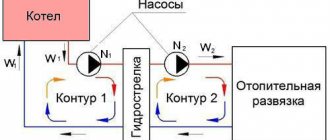
Modern heating systems are complex equipment with a flexible control mechanism. Trying to design such a system “by eye” will make it ineffective and your costs unreasonably high. Proper design includes a preliminary hydraulic calculation of the heating system based on specific parameters. Let's figure out what values help optimize capital costs, improve system performance, avoid abnormal operating conditions, and also how to do this using an online calculator.
Heating diagram for a small private house Source huebschmann-hof.de
The benefits of calculation: why is it done?
The main difficulty of water heating systems is the use of a moving coolant under variable thermal conditions of external conditions. Any water heating system (WHS) consists of three parts: a device that generates heat, as well as elements that transport and release heat to the desired point in the house.
An ideal, “spherical” heat exchanger ensures complete heat transfer from the source through the coolant, but in reality, energy losses are inevitable in the process of transferring energy through the system. In order to get as close as possible to the standard, any project is based on hydraulic calculations. Calculations help make the system efficient, as they allow us to solve the following practical issues:
- The parameters of the coolant are determined: its volume and speed of movement sufficient to maintain the selected thermal balance. The main difficulty of such calculations is the influence of air temperature fluctuations.
- They minimize capital investments during construction (due to the selection of system elements with the required parameters) and operating costs.
- Establishes optimal operating modes for all components and devices, which leads to increased operating efficiency and postponement of major repairs.
Heating scheme with heated floors Source sevmarka.com
- They ensure proportional distribution of heat throughout the premises, guaranteeing the preservation of the level of thermal energy for the maximum period.
- Determine the parameters that make the system stable, reliable and silent.
Heat generator power
One of the main components of the heating system is the boiler: electric, gas, combined – it doesn’t matter at this stage. Because its main characteristic is important to us - power, that is, the amount of energy per unit of time that will be spent on heating.
The power of the boiler itself is determined by the formula below:
Wboiler = (Sroom*Wshare) / 10,
Where:
- Sroom – the sum of the areas of all rooms that require heating;
- Wdel – specific power taking into account the climatic conditions of the location (this is why it was necessary to know the climate of the region).
Typically, for different climatic zones we have the following data:
- northern regions – 1.5 – 2 kW/m2;
- central zone – 1 – 1.5 kW/m2;
- southern regions – 0.6 – 1 kW/m2.
These figures are quite arbitrary, but nevertheless provide a clear numerical answer regarding the influence of the environment on the apartment heating system.
This map shows climate zones with different temperature regimes. The location of the housing relative to the zone determines how much energy needs to be spent on heating a square meter of kWatt of energy (+)
The amount of the apartment area that needs to be heated is equal to the total area of the apartment and is equal, that is, 65.54-1.80-6.03 = 57.71 m2 (minus the balcony). The specific boiler power for the central region with cold winters is 1.4 kW/m2. Thus, in our example, the calculated power of the heating boiler is equivalent to 8.08 kW.
Types of SVO wiring
Although the operating principle of the heating system is the same (receiving and distributing heat throughout the home), its work can be organized in different ways. It is convenient to distinguish systems by the method of organizing circulation. Natural circulation is possible, when the coolant moves due to gravity, and forced circulation, when a pump copes with it.
Water heating circuits differ in configuration and scale; they can be single-pipe or double-pipe. They are subject to different laws, so the hydraulic calculation of the pipeline is carried out taking into account the differences. The following types of single-pipe heating circuits are common:
- With lower wiring (popular name “Leningradka”). The pipe passes through all the rooms in a circle and returns to the boiler. The advantage of the system: it has few pipes, its thermal power does not exceed 30-35 kW. The downside is the uneven distribution of heat and the impossibility of regulation.
Single-pipe circuit with bottom wiring Source termokraft.ru
- With top wiring (Moscow system). The supply line is located above the heating devices. The system can operate without power supply; the temperature in the batteries is distributed evenly thanks to the calculation and pipes with different diameters. The downside is the difficulty of smooth adjustment.
Two-pipe wiring is presented in the following varieties:
- Dead end system. A common option in which the working medium is supplied and removed from each battery through different lines (direct and return). This heating arrangement is found in different types of housing; its peculiarity is that the direct line (supplying heat) is longer than the return line.
- Two-pipe associated system (Tichelman loop). The return line starts from the first radiator, then the returns from the remaining radiators are connected to it, after which the coolant returns to the boiler. It turns out that along the forward and return lines the working medium moves in one (corresponding) direction. The system operates stably, distributes heat well, but is the most material-intensive.
Return line - Tichelman loop Source izion.pro
- Beam wiring (also known as fan, collector, cabinet). The pipes radiate from one point (the collector), and the control is also located here. The advantage of the wiring: it makes it possible to separately adjust the temperature (or turn off) of each device. The system is easy to automate and is simple to design and calculate the pipeline. Disadvantage: high installation costs due to the large number of pipes.
See also: Catalog of companies that specialize in water supply, sewerage and related work
Heating systems with dead-end and associated movement of coolant
Note that in radiator wiring systems, with a single principle of hydraulic calculation, there are different approaches, because systems are divided into dead-end and associated.
In a dead-end circuit, the coolant moves through the “supply” and “return” pipes in opposite directions. And, accordingly, in a passing scheme, the coolant moves through the pipes in one direction.
This affects the hydraulic calculation method.
In dead-end systems, calculations are carried out through the farthest - most loaded sections. For this purpose, the main circulation ring is selected. This is the most unfavorable direction for water, according to which the diameters of heating pipes are primarily selected. All other secondary rings that arise in this system must be linked to the main one. In the associated system, calculations are carried out through the middle, most loaded, riser.
In plumbing systems, a similar principle is followed. The system is calculated through the most distant and most loaded riser. But there is a peculiarity - in calculating expenses.
Important: if in radiator wiring the flow rate depends on the amount of heat and temperature changes , then in the water supply system the flow rate depends on the norms of water consumption, as well as on the type of installed water fittings.
Preparation for calculation and its stages
Hydraulic heating calculation allows you to find out what operational parameters the heating system should have with given initial data in order to demonstrate better efficiency. At this stage of the project, it is necessary to obtain the following characteristics:
- Pipe diameter (it determines the throughput of the system).
- Head and pressure losses. The total losses (across the entire northwestern district) and separately for each section are calculated.
- The optimal volume of water in the circuit, the speed of its movement, the capacity of the expansion tank.
- Calculation of system resistance, selection of circulation pump.
Table for determining the diameter of pipes Source oboiman.ru
Before calculating the hydraulic parameters, it is necessary to perform a thermal calculation. It will give you an idea of how much heating energy is needed for each room. This, in turn, will allow you to choose the type of heating system, heat generator and heating devices.
Based on these data, pipes and fittings, a methodology are selected, and the pipeline is calculated based on flow and pressure. At the last stage, an axonometric wiring diagram is drawn up (a visual projection of communication networks made in a three-coordinate system).
Dynamic parameters of the coolant
We move on to the next stage of calculations - analysis of coolant consumption. In most cases, the heating system of an apartment differs from other systems - this is due to the number of heating panels and the length of the pipeline. Pressure is used as an additional “driving force” for flow vertically through the system.
In private one- and multi-story buildings, old panel apartment buildings, high-pressure heating systems are used, which makes it possible to transport the heat-releasing substance to all sections of the branched, multi-ring heating system and raise water to the entire height (up to the 14th floor) of the building.
On the contrary, an ordinary 2- or 3-room apartment with autonomous heating does not have such a variety of rings and branches of the system; it includes no more than three circuits.
This means that the coolant is transported using the natural process of water flow. But you can also use circulation pumps; heating is provided by a gas/electric boiler.
We recommend using a circulation pump for heating rooms larger than 100 m2. The pump can be installed either before or after the boiler, but usually it is installed on the “return” - lower fluid temperature, less airiness, longer pump life
Specialists in the field of design and installation of heating systems define two main approaches in terms of calculating the volume of coolant:
- According to the actual capacity of the system. Without exception, all volumes of cavities where the flow of hot water will flow are summed up: the sum of individual sections of pipes, sections of radiators, etc. But this is a rather labor-intensive option.
- According to boiler power. Here the opinions of experts differ greatly, some say 10, others 15 liters per unit of boiler power.
From a pragmatic point of view, you need to take into account the fact that probably the heating system will not only supply hot water for the room, but also heat water for the bath/shower, washbasin, sink and dryer, and maybe for a hydromassage or jacuzzi. This option is simpler.
Therefore, in this case, we recommend setting 13.5 liters per unit of power. Multiplying this number by the boiler power (8.08 kW) we obtain the estimated volume of water mass - 109.08 liters.
The calculated coolant velocity in the system is precisely the parameter that allows you to select a certain pipe diameter for the heating system.
It is calculated using the following formula:
V = (0.86*W*k)/t-to,
Where:
- W – boiler power;
- t – temperature of the supplied water;
- to – water temperature in the return circuit;
- k – boiler efficiency (0.95 for a gas boiler).
Substituting the calculated data into the formula, we have: (0.86 * 8080 * 0.95)/80-60 = 6601.36/20 = 330 kg/h. Thus, in one hour, 330 liters of coolant (water) move through the system, and the system capacity is about 110 liters.
Principles of hydraulic calculation
Thermal calculation provides the following data:
- For a water cooler with a single-pipe circuit: coolant flow (kg/h).
- For a water cooler with a two-pipe circuit: the difference between the hot and cooled working fluid (in the forward and reverse parts).
- Optimal speed of coolant movement; it is in the range of 0.3-0.7 m/s. If it falls below 0.2 m/s, there is a risk of airing. The speed is related to the inner diameter of the pipe, this relationship is inversely proportional.
Limit speeds of coolant movement Source ytimg.com
How data is collected
The hydraulic calculation of the system is mostly based on calculations related to the calculation of heating based on the area of the room.
Therefore, it is necessary to have the following information:
- the area of each individual room;
- dimensions of window and door connectors (internal doors have practically no effect on heat loss);
- climatic conditions, features of the region.
We will proceed from the following data. Living room area - 18.83 m2, bedroom - 14.86 m2, kitchen - 10.46 m2, balcony - 7.83 m2 (total), corridor - 9.72 m2 (total), bathroom - 3.60 m2, toilet - 1.5 m2. Entrance doors - 2.20 m2, common room window - 8.1 m2, bedroom window - 1.96 m2, kitchen window - 1.96 m2.
The height of the apartment walls is 2 meters 70 cm. The external walls are made of class B7 concrete plus internal plaster, 300 mm thick. Internal walls and partitions - load-bearing 120 mm, ordinary - 80 mm. The floor and, accordingly, the ceiling are made of concrete floor slabs of class B15, thickness 200 mm.
The layout of this apartment provides the opportunity to create one single heating branch passing through the kitchen, bedroom and living room, which will ensure an average temperature of 20-22⁰C in the rooms (+)
What about the environment? The apartment is located in a house located in the middle of a microdistrict of a small town. The city is located in a certain lowland, the altitude above sea level is 130-150 m. The climate is moderate continental with cool winters and fairly warm summers.
Average annual temperature is +7.6°C. The average temperature in January is -6.6°C, in July +18.7°C. Wind - 3.5 m/s, average air humidity - 74%, precipitation 569 mm.
Analyzing the climatic conditions of the region, it should be noted that we are dealing with a wide range of temperatures, which in turn affects the special requirement for adjusting the heating system of the apartment.
Process automation
The pressure in the pipeline can be calculated using online calculators that offer hydraulic calculations of the system. You can obtain such characteristics as water flow (throughput), pipe parameters (internal diameter), as well as pressure loss in the pipeline; The calculator allows you to choose the method of calculating resistance.
An example of calculating parameters in a calculator Source oboiman.ru
Resistance can be calculated based on the material and length of the water pipeline section, or based on the type of material (steel, cast iron, asbestos cement, reinforced concrete, plastic, glass) and its roughness (dynamic resistance coefficient). You can also specify the type of pipes: new or not, as well as the material of the external or internal coating. In addition to the pressure drop, the hydraulic calculator calculates the flow rate, internal diameter, and length of the section.
Performing calculations using an online calculator is suitable for small systems consisting of one or two circuits with several radiators in each. More complex and powerful SVO (over 30 kW) require calculations using software. The necessary software is developed by the largest manufacturers of heating equipment.
Program window for calculating the heating of a private house Source ytimg.com
Design features
For a gravity system to work effectively, the following requirements must be met:
- the heat source is any non-volatile heat generator with outlet pipes with a diameter of 40-50 mm;
- at the outlet of a boiler or stove with a water circuit, an accelerating riser is immediately installed - a vertical pipe through which the heated coolant rises;
- the riser ends with an open-type expansion tank installed in the attic or under the ceiling of the upper floor (depending on the type of wiring and the design of the private house);
- tank capacity – 10% of the coolant volume;
- by gravity, it is advisable to choose heating devices with large internal channels - cast iron, aluminum, bimetallic;
- for better heat transfer, heating radiators are connected according to a versatile pattern - bottom or diagonal;
- special full-bore valves with thermal heads (supply) and balancing valves (return) are installed on the radiator connections;
- It is better to equip batteries with manual air vents - Mayevsky taps;
- replenishment of the heating network is organized at the lowest point - near the boiler;
- all horizontal sections of pipes are laid with slopes, the minimum is 2 mm per linear meter, the average is 5 mm/1 m.
On the left in the photo is the coolant supply riser from a floor-standing boiler with a pump on the bypass, on the right is the return line connection
Gravity heating systems are made open and operated at atmospheric pressure. But will gravity flow work in a closed circuit with a membrane tank? We answer: yes, natural circulation will continue, but the speed of the coolant will decrease and efficiency will drop.
It is not difficult to substantiate the answer; it is enough to mention the change in the physical properties of liquids under excess pressure. With a pressure in the system of 1.5 Bar, the boiling point of water will shift to 110 °C, and its density will also increase. The circulation will slow down due to the small difference in the masses of the hot and cooled flow.
Simplified gravity flow diagrams with an open and membrane expansion tank
Briefly about the main thing
Designing heating systems allows you to select the optimal parameters: sufficient water supply, suitable pipe characteristics, pressure of circulation pumps. Hydraulic calculation is one of the most important parts of design. It allows you to balance the selected type of heating system, ensures its stable operation and durable use.
In hydraulic calculations, parameters such as pressure drop, water flow, and pipe diameter for each section are determined. A small system for a private home can be calculated manually (using formulas and reference books) or using an online calculator. For complex and powerful heating circuits, it is advisable to use specialized programs.
Summarizing
It has already been said above that hydraulic calculation of a heating system is a complex task that requires professional knowledge. If you have to design a highly ramified heating system (large house), then manual calculations take a lot of effort and time. To simplify this task, special computer programs have been developed.
Sergei Bulkin
Using these programs, you can make hydraulic calculations, determine the adjustment characteristics of shut-off and control valves, and automatically create a custom specification. Depending on the type of program, calculations are carried out in the AutoCAD environment or in your own graphic editor.
Let us add that now, when designing industrial and civil facilities, there is a tendency to use BIM technologies (building information modeling). In this case, all designers work in a single information space. For this purpose, a “cloud” model of the building is created. Thanks to this, any inconsistencies are identified at the design stage, and the necessary changes are made to the project in a timely manner. This allows you to accurately plan all construction work, avoid delays in the completion of the project and thereby reduce the estimate.
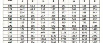
Quick selection of pipe diameters from the table
For houses up to 250 sq.m. provided that there is a 6-piece pump and radiator thermal valves, you don’t have to do a full hydraulic calculation. You can select the diameters from the table below. On short sections you can slightly exceed the power. Calculations were made for coolant Δt=10oC and v=0.5m/s.
| Pipe | Radiator power, kW |
| Pipe 14x2 mm | 1.6 |
| Pipe 16x2 mm | 2,4 |
| Pipe 16x2.2 mm | 2,2 |
| Pipe 18x2 mm | 3,23 |
| Pipe 20x2 mm | 4,2 |
| Pipe 20x2.8 mm | 3,4 |
| Pipe 25x3.5 mm | 5,3 |
| Pipe 26x3 mm | 6,6 |
| Pipe 32x3 mm | 11,1 |
| Pipe 32x4.4 mm | 8,9 |
| Pipe 40x5.5 mm | 13,8 |
Discuss this article, leave a review in | |
Transporting hot water
The algorithm for the calculation scheme is established by regulatory and technical documentation, state and sanitary standards and is carried out in strict accordance with the established procedure.
The article provides an example of a hydraulic calculation of a heating network. The procedure is performed in the following sequence:
The numbering system should clearly separate the types of networks: intra-block main lines, inter-house ones from the thermal well to the boundaries of the balance sheet, while the section is established as a section of the network, enclosed by two branches.
The diagram shows all the parameters of the hydraulic calculation of the main heating network from the central heating substation:
- Q - GJ/hour;
- G m3/hour;
- D – mm;
- V - m/s;
- L is the length of the section, m.
The diameter is calculated using the formula.
Valtec “Sputnik” equipment configurator
Configurator software is a modular configurator for various metering devices and equipment. Allows commissioning of the Valtec “Sputnik” automated energy metering system.
- The configurator includes the following modules:
- polling of metering devices via radio channel using radio modem VT.WRM.MASTER.0
- module for reading data from VT.WRM hubs
- module for configuring wireless pulse counter-recorder GSM/GPRS VT.WLR.GSM
- module for configuring a wireless pulse counter-recorder with a radio channel (LoRAWAN 868 MHz) VT.LR
- module for configuring pulse counter-recorder SIPU (RS485/M-Bus) VT.MB/ VT.RS
VHM-T Service. Program for working with VALTEC heat meters
- The VHM-T Service program is designed to work with VALTEC VHM-T heat meters in terms of:
- reading current meter readings and characteristics;
- working with daily, monthly and annual archives;
- generation of thermal energy consumption accounting sheets;
- settings of date, time and automatic transition to summer/winter time (if necessary);
- counter settings for operation in automated data accounting systems.
Work computer software requirements
- operating system Windows XP Service Pack 3 (32/64 bit) or higher;
- Visual C++ Redistributable Packages for Visual Studio 2013 (free download available from microsoft.com). As a rule, these packages are already present in versions of Windows 7 and higher with the latest updates.
The interaction of the working computer with the heat meter is carried out through an optoelectronic sensor with the appropriate drivers installed in the system.
Setting up communication between the program and the meter
- Connect the optoelectronic sensor to the computer.
- On the front panel of the heat meter, press and hold the button (about 8 seconds) until the “=” symbol appears in the lower right corner of the screen.
- Bring the optoelectronic sensor to the opto-receiver of the meter on the front panel.
- Give a command to establish a connection in the program.
— Windows XP/Server 2003/Vista/7/8/8.1 (v6.7)
To activate the program, you must register again. The activation key is sent to the user's email address within 1-2 days.
If you have any questions about working with the program, you can ask them at:
Programs for old-style counters
Instrumental geographic information system
GIS Zulu is a geoinformation program for hydraulic calculation of heating networks. The company specializes in research into GIS applications that require visualization of 3D geodata in vectorial and raster versions, topological study and their relationship with semantic databases. Zulu allows you to create different plans and working diagrams, including heat and steam networks using topology, can work with rasters and acquire data from different databases, such as BDE or ADO.
You may be interested in:Industrial reverse osmosis installation: rules, installation instructions, filters and operating principle
The calculations are carried out in close integration with the geographic information system; they are implemented in an extended module version. The network is easily and quickly entered into the GIS using the mouse or using these coordinates. After which a calculation scheme is immediately created. Afterwards, the circuit parameters are set and the start of the process is confirmed. Calculations are used for dead-end and ring heating networks, including network pumping units and throttling devices, powered from one or many sources. Heating calculations can be carried out taking into account leaks from distribution networks and heat losses in heating pipes.
In order to install a special program on a PC, download “Hydraulic calculation of heating networks 3.5.2” on the Internet via torrent.
Structure of definition stages:
Microsoft Excel Developer Tool
Microsoft Excel for hydraulic calculations in heating networks is the most accessible tool for users. Its comprehensive spreadsheet editor can solve many computing problems. However, when performing calculations of thermal systems, special requirements must be met. These can be listed:
- finding the previous section in the direction of movement of the medium;
- calculation of the pipe diameter based on a given conditional indicator and reverse calculation;
- establishing a correction factor for the size of the specific pressure loss based on the data and the equivalent roughness of the pipe material;
- calculating the density of a medium from its temperature.
Of course, the use of Microsoft Excel for hydraulic calculations in heating networks does not make it possible to completely simplify the calculation process, which initially creates relatively large labor costs.
Software for hydromechanical calculations of networks or the GRTS package is a computer application that performs hydromechanical calculations of multi-pipe networks, including a dead-end configuration. The GRTS platform contains formula language functionality that allows you to establish the necessary calculation characteristics and select formulas for the accuracy of their determination. Due to the use of this functionality, the calculator has the opportunity to independently find the computing technology and set the required complexity.
There are two modifications of the GRTS application: 1.0 and 1.1. Upon completion, the user will receive the following results:
- calculation, in which the calculation methodology is carefully described;
- report in tabular form;
- transfer of computational databases to Microsoft Excel;
- piezometric graph;
- coolant temperature graph.
The GRTS 1.1 application is considered the most modern modification and supports the latest standards:
Determination of pressure loss in pipes
The pressure loss resistance in the circuit through which the coolant circulates is determined as its total value for all individual components. The latter include:
- losses in the primary circuit, denoted as ∆Plk;
- local coolant costs (∆Plм);
- pressure drop in special zones called “heat generators” under the designation ∆Ptg;
- losses inside the built-in heat exchange system ∆Pto.
After summing these values, the desired indicator is obtained, characterizing the total hydraulic resistance of the system ∆Pco.
In addition to this generalized method, there are other methods for determining pressure loss in polypropylene pipes. One of them is based on a comparison of two indicators tied to the beginning and end of the pipeline. In this case, the pressure loss can be calculated by simply subtracting its initial and final values, determined by two pressure gauges.
Another option for calculating the required indicator is based on the use of a more complex formula that takes into account all the factors that affect the characteristics of the heat flow. The ratio given below primarily takes into account the loss of fluid pressure due to the large length of the pipeline.
- h – liquid pressure loss, in the case under study measured in meters.
- λ – coefficient of hydraulic resistance (or friction), determined using other calculation methods.
- L is the total length of the serviced pipeline, which is measured in linear meters.
- D – internal pipe size, which determines the volume of coolant flow.
- V is the speed of fluid flow, measured in standard units (meter per second).
- The symbol g is the acceleration due to gravity, equal to 9.81 m/s2.
Pressure losses occur due to friction of the fluid against the inner surface of the pipes.
Of great interest are the losses caused by the high coefficient of hydraulic friction. It depends on the roughness of the internal surfaces of the pipes. The ratios used in this case are valid only for pipe blanks of a standard round shape. The final formula for finding them looks like this:
- V is the speed of movement of water masses, measured in meters/second.
- D is the internal diameter, which determines the free space for the coolant to move.
- The coefficient in the denominator indicates the kinematic viscosity of the liquid.
The last indicator refers to constant values and is found using special tables published in large quantities on the Internet.