A little about theory and tasks
The main task of the hydraulic calculation of heating networks is the selection of geometric parameters of the pipe and standard sizes of control elements to ensure:
- qualitative and quantitative distribution of coolant to individual heating devices;
- thermal-hydraulic reliability and economic feasibility of a closed thermal system;
- optimization of investment and operating costs of the heat supply organization.
You may be interested in: Pokrovsky Mine OJSC (Tygda, Magdagachinsky district, Amur region) - a primary gold deposit developed by open pit mining
Hydraulic calculation of heating networks creates the prerequisites for heating and hot water devices to achieve the required power at a given temperature difference. For example, with a T-graph of 150-70 °C, it will be equal to 80 °C. This is achieved by creating the required water pressure or coolant pressure at each heating point.
This mandatory condition for the operation of a heating system is implemented through proper configuration of network equipment in accordance with design conditions, installation of equipment based on the results of hydraulic calculations of heating networks.
Network hydraulic stages:
- Pre-launch calculation.
- Operational regulation.
- using calculations;
- measuring method.
The initial hydraulics of the network is performed:
You may be interested in: Metallurgical, St. Petersburg
In the Russian Federation, the calculation method is predominant; it determines all the parameters of the elements of the heat supply system in a single design area (house, block, city). Without this, the network will be misregulated, and the coolant will not be supplied to the upper floors of multi-story buildings. That is why the beginning of the construction of any heating supply facility, even the smallest one, begins with a hydraulic calculation of heating networks.
Drawing up a diagram of heating networks
Before hydraulic calculations, a preliminary pipeline diagram is performed indicating the length L in meters and D of utility water pipelines in mm and the estimated volumes of network water for the design sections of the diagram. Pressure losses in heat supply systems are divided into linear, which arise due to the carrier rubbing against the pipe walls, and losses in areas caused by local structural resistance due to the presence of tees, bends, compensators, turns and other devices.
Calculation example: hydraulic calculation of heating networks:
Determination of coolant flow and pipe diameters
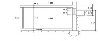
First, each heating branch must be divided into sections, starting from the very end. The breakdown is done by water consumption, and it varies from radiator to radiator. This means that after each battery a new section begins, this is shown in the example presented above. We start from the 1st section and find the mass flow rate of the coolant in it, focusing on the power of the last heating device:
G = 860q/ ∆t, where:
- G – coolant flow, kg/h;
- q – thermal power of the radiator in the area, kW;
- Δt – temperature difference in the supply and return pipelines, usually 20 ºС.
For the first section, the coolant calculation looks like this:
860 x 2 / 20 = 86 kg/h.
The result obtained must be immediately plotted on the diagram, but for further calculations we will need it in other units - liters per second. To make a translation, you need to use the formula:
GV = G /3600ρ, where:
- GV – volumetric water flow, l/sec;
- ρ – density of water, at a temperature of 60 ºС is equal to 0.983 kg / liter.
We have: 86 / 3600 x 0.983 = 0.024 l/sec. The need to convert units is explained by the need to use special ready-made tables to determine the diameter of a pipe in a private house. They are freely available and are called “Shevelev tables for hydraulic calculations.” You can download them by following the link: https://dwg.ru/dnl/11875
These tables show the diameters of steel and plastic pipes depending on the flow rate and speed of the coolant. If you open page 31, then in Table 1 for steel pipes the first column shows the flow rate in l/sec. In order not to make a full calculation of pipes for the heating system of a private home, you just need to select the diameter according to the flow rate, as shown in the figure below:
Note. In the left column, under the diameter, the speed of water movement is immediately indicated. For heating systems, its value should be in the range of 0.2–0.5 m/sec.
So, for our example, the internal passage size should be 10 mm. But since such pipes are not used in heating, we can safely accept a DN15 (15 mm) pipeline. We put it on the diagram and move on to the second section. Since the next radiator has the same power, there is no need to apply formulas; we take the previous water flow and multiply it by 2 and get 0.048 l/sec. We turn to the table again and find the closest suitable value in it. At the same time, do not forget to monitor the water flow speed v (m/sec) so that it does not exceed the specified limits (in the figures it is marked in the left column with a red circle):
Important. For heating systems with natural circulation, the coolant movement speed should be 0.1-0.2 m/sec.
As can be seen in the figure, section No. 2 is also laid with a DN15 pipe. Next, using the first formula, we find the flow rate in section No. 3:
860 x 1.5 / 20 = 65 kg/h and convert it to other units:
65 / 3600 x 0.983 = 0.018 l/sec.
Adding it to the sum of the costs of the two previous sections, we get: 0.048 + 0.018 = 0.066 l/sec and again turn to the table. Since in our example we are not calculating a gravitational system, but a pressure one, then in terms of coolant speed, a DN15 pipe is suitable this time too:
Following this path, we calculate all the areas and plot all the data on our axonometric diagram:
Applications of the normative method
You may be interested in: Steel X12F1: characteristics and application
Hydraulics of networks is carried out on the basis of tables of maximum hourly heat loads and a heat supply diagram for a city or region, indicating the sources, location of the main, intra-block and intra-house engineering systems, indicating the boundaries of the balance sheet ownership of the network owners. Hydraulic calculation of heating network pipelines for each section up to the above diagram is carried out separately.
This calculation method is used not only for heating networks, but also for all pipelines transporting liquid media, including gas condensate and other chemical liquid media. For pipeline heat supply systems, changes must be made taking into account the kinematic viscosity and density of the media. This is due to the fact that these characteristics influence the specific pressure loss in the pipes, and the flow rate is related to the density of the transit medium.
Parameters of hydraulic calculation of water heating network
Heat consumption Q and the amount of coolant G for areas are indicated in the table of maximum hourly heat consumption indicators for the winter and summer seasons separately and corresponds to the amount of heat consumption for the quarters included in the scheme.
An example of a hydraulic calculation of a heating network is presented below.
Since calculations depend on many indicators, they are performed using numerous tables, diagrams, graphs, nomograms, the final value of heat consumption Q for intra-house heating systems is obtained by interpolation.
The amount of liquid circulating in the heating network m3/hour, when calculating the hydraulic mode of the heating network, is determined by the formula:
G = (D2 / 4) x V,
Where:
- G—carrier consumption, m3/hour;
- D – pipeline diameter, mm;
- V—flow velocity, m/s.
Linear pressure drops in the hydraulic calculation of heating networks are taken from special tables. When installing heating systems, dozens and hundreds of auxiliary elements are installed in them: valves, fittings, vents, bends and others that create resistance to the transit environment.
The reasons for the drop in pressure in pipelines also include the internal state of the pipe materials and the presence of salt deposits on them. The coefficient values used in technical calculations are given in the tables.
Sequence of calculation steps
Speaking about the calculation of the heating system, we note that this procedure is the most controversial and important in terms of design.
Before performing the calculation, you need to perform a preliminary analysis of the future system, for example:
- establish a thermal balance in all and specifically each room of the apartment;
- approve thermostats, valves and pressure regulators;
- select radiators, heat exchange surfaces, heat-dissipating panels;
- determine areas of the system with maximum and minimum coolant flow.
In addition, it is necessary to determine the general scheme for transporting the coolant: full and small circuit, single-pipe system or two-pipe main.
As a result of the hydraulic calculation, we obtain several important characteristics of the hydraulic system, which provide answers to the following questions:
- what should be the power of the heating source;
- what is the flow rate and speed of the coolant;
- what is the required diameter of the main heating pipeline;
- what are the possible losses of heat and the mass of the coolant itself.
Another important aspect of hydraulic calculation is the procedure for balancing (linking) all parts (branches) of the system during extreme thermal conditions using control devices.
There are several main types of heating products: cast iron and aluminum multi-section, steel panel, bimetallic radiators and covectors. But the most common are aluminum multi-section radiators
The design zone of the pipeline main is a section with a constant diameter of the main itself, as well as a constant flow of hot water, which is determined by the formula for the heat balance of rooms. The listing of design zones starts from the pump or heat source.
Standard Methodology and Process Steps
According to the method of hydraulic calculation of heating networks, it is carried out in two stages:
The first to carry out calculations for the main highway is the costs established according to the scheme. In this case, reference data on specific pressure losses in networks are used.
Next, having calculated the diameters of the pipes, calculate:
Pressure losses are calculated using formulas and nomograms. Then, having this data for the entire network, they calculate the hydromechanical regime of individual sections from the point of flow splitting up to the end subscriber.
Calculations are linked to the choice of branch pipe diameters. Inconsistency no more than 10%. Excess pressure in the heating network is extinguished at elevator units, throttle nozzles or automatic regulators at in-house control points.
You may be interested in: Airplane propeller: name, classification and characteristics
Given the available pressure of the main heating network and branches, first set the approximate resistivity Rm, Pa/m.
The calculations use tables, nomograms for the hydraulic calculation of pipelines of heating networks and other reference literature, which is mandatory for all stages; it is easy to find on the Internet and in specialized literature.
Transporting hot water
The algorithm for the calculation scheme is established by regulatory and technical documentation, state and sanitary standards and is carried out in strict accordance with the established procedure.
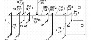
The article provides an example of a hydraulic calculation of a heating network. The procedure is performed in the following sequence:
The numbering system should clearly separate the types of networks: intra-block main lines, inter-house ones from the thermal well to the boundaries of the balance sheet, while the section is established as a section of the network, enclosed by two branches.
The diagram shows all the parameters of the hydraulic calculation of the main heating network from the central heating substation:
- Q - GJ/hour;
- G m3/hour;
- D – mm;
- V - m/s;
- L is the length of the section, m.
The diameter is calculated using the formula.
Steam heating networks
This heating network is designed for a heat supply system using coolant in the form of steam.
The differences between this scheme and the previous one are caused by temperature indicators and environmental pressure. Structurally, these networks are characterized by a shorter length; in large cities they usually include only main lines, i.e. from the source to the central heating point. They are not used as intra-district and intra-house networks, except at small industrial sites.
The schematic diagram is carried out in the same order as with water coolant. At the sections, all network parameters are indicated for each branch; data is taken from a summary table of maximum hourly heat consumption, with step-by-step summation of consumption indicators from the end consumer to the source.
The geometric dimensions of pipelines are established based on the results of hydraulic calculations, which are performed in accordance with state norms and regulations, and in particular SNiP. The determining value is the pressure loss of the gas-condensate medium from the heat supply source to the consumer. With a greater pressure loss and a smaller distance between them, the speed of movement will be high, and a smaller diameter of the steam line will be required. The diameter is selected according to special tables, based on the parameters of the coolant. The data is then entered into pivot tables.
Definition of resistance
Engineers are often faced with calculations of heat supply systems for large facilities. Such systems require a large number of heating devices and hundreds of linear meters of pipes. You can calculate the hydraulic resistance of a heating system using equations or special automated programs.
To determine the relative heat loss for adhesion in the line, the following approximate equation is used: R = 510 4 v 1.9 / d 1.32 (Pa/m). The use of this equation is justified for speeds of no more than 1.25 m/s.
If the value of hot water consumption is known, then an approximate equation is used to find the cross-section inside the pipe: d = 0.75 √G (mm). After receiving the result, you will need to refer to a special table to obtain the cross-section of the nominal diameter.
The most tedious and labor-intensive calculation will be the calculation of local resistance in the connecting parts of the pipeline, control valves, gate valves and heating devices.
Coolant for condensate network
The calculation for such a heating network differs significantly from the previous ones, since condensate simultaneously exists in two states - in steam and in water. This ratio changes as it moves towards the consumer, i.e. the steam becomes more and more wet and eventually turns completely into a liquid. Therefore, calculations for pipes for each of these media are different and are taken into account by other standards, in particular SNiP 2.04.02-84.
The procedure for calculating condensate pipelines:
The design features of this type of network significantly affect the quality of measurements, since the pipelines for this type of coolant are made of black steel; sections of the network after the network pumps, due to air leaks, quickly corrode from excess oxygen, after which low-quality condensate with iron oxides is formed, which causes metal corrosion. Therefore, it is recommended to install stainless steel pipelines in this area. Although the final choice will be made after completion of the feasibility study of the heating network.
Hydraulic linkage
Balancing pressure drops in the heating system is carried out using control and shut-off valves.
Hydraulic linking of the system is carried out on the basis of:
- design load (coolant mass flow);
- data from pipe manufacturers on dynamic resistance;
- the number of local resistances in the area under consideration;
- technical characteristics of fittings.
Installation characteristics - pressure drop, fastening, throughput - are set for each valve. They are used to determine the coefficients of coolant flow into each riser, and then into each device.
Pressure loss is directly proportional to the square of the coolant flow rate and is measured in kg/h, where
S is the product of dynamic specific pressure, expressed in Pa/(kg/h), and the reduced coefficient for local resistance of the section (ξpr).
The given coefficient ξpr is the sum of all local resistances of the system.
Design programs
Energy losses due to valves, fittings and bends are caused by localized flow disturbances. Energy loss occurs along a finite and not necessarily short section of the pipeline, however, for hydraulic calculations it is generally accepted that the entire volume of this loss is taken into account at the location of the device. For piping systems with relatively long pipes, it is often the case that the resulting losses will be negligible in relation to the total pressure loss in the pipe.
Pipeline losses are measured using actual experimental data and then analyzed to determine a local loss factor that can be used to calculate fitting losses as it varies with the rate of fluid flow through the device.
Pipe Flow Software products make it easy to determine fitting losses and other losses in pressure drop calculations because they come pre-loaded with a valve database that contains many standard factors for various sized valves and fittings. Within a piping system, a pump is often used to add additional pressure to overcome losses due to friction and other resistance.
The pump performance is determined by the curve. The head produced by the pump varies depending on the flow rate, finding the operating point on the pump performance curve is not always an easy task.
Using the Pipe Flow Expert hydraulic design software, it is quite easy to find the exact operating point on the pump curve, ensuring that flows and pressures are balanced throughout the system, to make accurate piping design decisions.
Online calculations are made in order to select the optimal diameter that provides the best operating parameters, low pressure losses and high speeds of fluid movement, which will ensure good technical and economic indicators of heating networks as a whole.
It minimizes effort and provides higher accuracy. It includes all the necessary reference tables and nomograms. Thus, losses per meter of pipes are assumed to be 81 - 251 Pa/m (8.1 - 25.1 mm water column), which depends on the material of the pipes. The water speed in the system depends on the diameter of the installed pipes and is selected in a specific range. The highest water speed for heating networks is 1.5 m/s. The calculation suggests boundary values of water speed in pipelines with an internal diameter:
Metal heating pipes
These products have proven themselves in the construction market for quite a long time, since they have a number of very obvious advantages:
- any, even the most significant pressure drops in the system will not interfere with the normal functioning of these pipes;
- due to the fact that the metal takes a long time to heat up and at the same time gives off heat for a long time, such structures can serve as an additional heating device like a radiator;
- the service life of metal pipes is very long;
- the reasonable cost of such products distinguishes them favorably from other modern pipeline systems.
However, they also have some negative aspects that cannot be ignored:
- installing a metal pipeline is quite difficult. This work requires a large set of specialized construction tools, which are not always available to the average user. In addition, the entire installation process requires a lot of physical and time investment;
- the mass of metal structures is very large, so to hold them, very strong walls of the house are required, which cannot always be provided (for example, if the basis of the partitions is plasterboard);
- cast iron, which is usually the main material in a metal pipe, is prone to the formation of a corrosive coating on it both from the inside and outside, and periodic cleaning, which cannot be avoided, is a very problematic procedure.
Instrumental geographic information system
GIS Zulu is a geoinformation program for hydraulic calculation of heating networks. The company specializes in research into GIS applications that require visualization of 3D geodata in vectorial and raster versions, topological study and their relationship with semantic databases. Zulu allows you to create different plans and working diagrams, including heat and steam networks using topology, can work with rasters and acquire data from different databases, such as BDE or ADO.
You may be interested in:Industrial reverse osmosis installation: rules, installation instructions, filters and operating principle
The calculations are carried out in close integration with the geographic information system; they are implemented in an extended module version. The network is easily and quickly entered into the GIS using the mouse or using these coordinates. After which a calculation scheme is immediately created. Afterwards, the circuit parameters are set and the start of the process is confirmed. Calculations are used for dead-end and ring heating networks, including network pumping units and throttling devices, powered from one or many sources. Heating calculations can be carried out taking into account leaks from distribution networks and heat losses in heating pipes.
In order to install a special program on a PC, download “Hydraulic calculation of heating networks 3.5.2” on the Internet via torrent.
Structure of definition stages:
Microsoft Excel Developer Tool
Microsoft Excel for hydraulic calculations in heating networks is the most accessible tool for users. Its comprehensive spreadsheet editor can solve many computing problems. However, when performing calculations of thermal systems, special requirements must be met. These can be listed:
- finding the previous section in the direction of movement of the medium;
- calculation of the pipe diameter based on a given conditional indicator and reverse calculation;
- establishing a correction factor for the size of the specific pressure loss based on the data and the equivalent roughness of the pipe material;
- calculating the density of a medium from its temperature.
Of course, the use of Microsoft Excel for hydraulic calculations in heating networks does not make it possible to completely simplify the calculation process, which initially creates relatively large labor costs.
Software for hydromechanical calculations of networks or the GRTS package is a computer application that performs hydromechanical calculations of multi-pipe networks, including a dead-end configuration. The GRTS platform contains formula language functionality that allows you to establish the necessary calculation characteristics and select formulas for the accuracy of their determination. Due to the use of this functionality, the calculator has the opportunity to independently find the computing technology and set the required complexity.
There are two modifications of the GRTS application: 1.0 and 1.1. Upon completion, the user will receive the following results:
- calculation, in which the calculation methodology is carefully described;
- report in tabular form;
- transfer of computational databases to Microsoft Excel;
- piezometric graph;
- coolant temperature graph.
The GRTS 1.1 application is considered the most modern modification and supports the latest standards:
Heat generator power
One of the main components of the heating system is the boiler: electric, gas, combined - it doesn’t matter at this stage. Because its main characteristic is important to us - power, that is, the amount of energy per unit of time that will be spent on heating.
The power of the boiler itself is determined by the formula below:
Wboiler = (Sroom*Wshare) / 10,
Where:
- Sroom - the sum of the areas of all rooms that require heating;
- Wdel is the specific power taking into account the climatic conditions of the location (this is why it was necessary to know the climate of the region).
Typically, for different climatic zones we have the following data:
- northern regions - 1.5 - 2 kW/m2;
- central zone - 1 - 1.5 kW/m2;
- southern regions - 0.6 - 1 kW/m2.
These figures are quite arbitrary, but nevertheless provide a clear numerical answer regarding the influence of the environment on the apartment heating system.
This map shows climate zones with different temperature regimes. The location of the housing relative to the zone determines how much energy needs to be spent on heating a square meter of kWatt of energy (+)
The amount of the apartment area that needs to be heated is equal to the total area of the apartment and is equal, that is, 65.54-1.80-6.03 = 57.71 m2 (minus the balcony). The specific boiler power for the central region with cold winters is 1.4 kW/m2. Thus, in our example, the calculated power of the heating boiler is equivalent to 8.08 kW.