Introduction
Requirements for determining the heat loads of consumers when developing heat supply schemes are reflected in the following regulatory and legislative acts:
- Federal Law of the Russian Federation of July 27, 2010 No. 190-FZ;
- Order of the Ministry of Regional Development of the Russian Federation dated February 28, 2009 No. 610;
Contract loads are usually calculated based on design data. Design heating loads mainly depend on the calculated parameters of the microclimate of the premises, the calculated temperature of the outside air during the heating period (assumed to be equal to the temperature of the coldest five-day period with a probability of 0.92 according to 8. SP 131.13330.2012) and the thermal insulation characteristics of enclosing structures. Design loads on hot water supply depend on the volume of hot water consumption and its design temperature.
Over the past 20-30 years, many of the parameters and characteristics listed above have changed several times. Methods for calculating thermal loads and requirements for thermal protection of enclosing structures have changed. In particular, the energy efficiency class of apartment buildings (ABCs) is determined based on a comparison (determining the deviation value) of actual or calculated (for newly built, reconstructed and overhauled ABMs) values of the indicator of specific annual consumption of energy resources, reflecting the specific consumption of energy resources for heating, ventilation, hot water supply and basic values of the specific consumption of energy resources in apartment buildings. In this case, the actual (calculated) values must be brought to the design conditions for comparability with the basic values. The actual values of the specific annual consumption of energy resources are determined based on the readings of common house meters.
The climate itself has also changed, as a result of which, for example, for St. Petersburg, the standard design temperature of the outside air has increased over thirty years, from –26 °C to –24 °C, the design duration of the heating period has decreased by 6 days, and the average The temperature of the heating period increased by 0.5 °C (from –1.8 to –1.3 °C).
In addition to the above factors, consumers of thermal energy themselves contribute to energy-saving measures, for example, by replacing wooden windows in apartments with more airtight plastic ones.
All these changes, taken together, contribute to the fact that the actual heat consumption and contractual heat loads of thermal energy consumers differ.
Examples of developed Heat Supply Schemes for a number of large settlements (for example, Nizhny Novgorod) have shown that if the contractual load (the load established in heat supply contracts) is taken as the actual load, this creates an excess capacity reserve of heat supply organizations. A significant portion of the load in this case turns out to be unclaimed, but at the same time constant operating costs remain, which negatively affects the efficiency of heat supply organizations (TSO) and the consumer of thermal energy.
The Strategy notes that the currently used technology for planning heat supply systems leads to unnecessary investments, the creation of excess thermal power in all elements of energy systems and the preservation of a low level of efficiency of the entire Russian energy sector.
The relevance of the topic raised in the article is due to the lack of methods in the current regulatory and legislative acts for determining actual heat loads in the design elements of the territorial division at design outdoor temperatures, the problems of reconciling the actual heat loads used for investment planning in heat supply schemes with TCO, as well as the consequences of incorrect analysis heat loads of consumers established in heat supply contracts.
Heat load distribution
For water heating, the maximum thermal power of the boiler should be equal to the sum of the thermal power of all heating devices in the house. The distribution of heating devices is influenced by the following factors:
- Living rooms in the middle of the house - 20 degrees;
- Corner and end living rooms - 22 degrees. At the same time, due to the higher temperature, the walls do not freeze;
- Kitchen - 18 degrees, since it has its own heat sources - gas or electric stoves, etc.
- Bathroom - 25 degrees.
With air heating, the heat flow that enters a separate room depends on the throughput of the air hose. Often the simplest way to adjust it is to adjust the position of the ventilation grilles with temperature control manually.
In a heating system that uses a distribution heat source (convectors, heated floors, electric heaters, etc.), the required temperature mode is set on the thermostat.
Energy survey of the designed operating modes of the heat supply system
When designing, the heat supply system of JSC Termotron-zavod was designed for maximum loads.
The system was designed for 28 heat consumers. The peculiarity of the heat supply system is that part of the heat consumers is from the output of the boiler room to the main building of the plant. Next, the heat consumer is the main building of the plant, and then the rest of the consumers are located behind the main building of the plant. That is, the main building of the plant is an internal heat consumer and a transit of heat supply for the last group of heat load consumers.
The boiler room was designed for 3 DKVR 20-13 steam boilers, running on natural gas, and 2 PTVM-50 hot water boilers.
One of the most important stages in the design of heating networks was the determination of design heat loads.
The estimated heat consumption for heating each room can be determined in two ways:
- from the room heat balance equation;
- according to the specific heating characteristics of the building.
The design values of thermal loads were made according to aggregated indicators, based on the volume of buildings by texture.
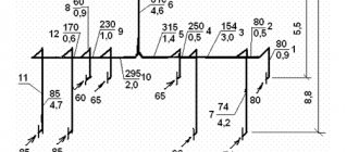
The estimated heat consumption for heating the i-th production premises, kW, is determined by the formula:
, (1)
where: is the coefficient for taking into account the area where the enterprise is being built:
(2)
where is the specific heating characteristic of the building, W/(m3.K);
— volume of the building, m3;
— calculated air temperature in the working area, ;
— the estimated outside air temperature for calculating the heating load, for the city of Bryansk is -24.
The determination of the estimated heat consumption for heating for the premises of the enterprise was carried out according to the specific heating load (Table 1).
Table 1 Heat consumption for heating for all premises of the enterprise
| No. | Object name | Building volume, V, m3 | Specific heating characteristic q0, W/m3K | Coefficient e | Heat consumption for heating , kW |
| 1 | Dining room | 9894 | 0,33 | 1,07 | 146,58 |
| 2 | Painting Research Institute | 888 | 0,66 | 1,07 | 26,46 |
| 3 | Scientific research institute TEN | 13608 | 0,33 | 1,07 | 201,81 |
| 4 | Electrical assembly engines | 7123 | 0,4 | 1,07 | 128,043 |
| 5 | Model site | 105576 | 0,4 | 1,07 | 1897,8 |
| 6 | Painting department | 15090 | 0,64 | 1,07 | 434,01 |
| 7 | Galvanic department | 21208 | 0,64 | 1,07 | 609,98 |
| 8 | Procurement area | 28196 | 0,47 | 1,07 | 595,55 |
| 9 | Thermal section | 13075 | 0,47 | 1,07 | 276,17 |
| 10 | Compressor room | 3861 | 0,50 | 1,07 | 86,76 |
| 11 | Forced ventilation | 60000 | 0,50 | 1,07 | 1348,2 |
| 12 | HR department extension | 100 | 0,43 | 1,07 | 1,93 |
| 13 | Forced ventilation | 240000 | 0,50 | 1,07 | 5392,8 |
| 14 | Container shop | 15552 | 0,50 | 1,07 | 349,45 |
| 15 | Factory management | 3672 | 0,43 | 1,07 | 70,96 |
| 16 | Class | 180 | 0,43 | 1,07 | 3,48 |
| 17 | Technical department | 200 | 0,43 | 1,07 | 3,86 |
| 18 | Forced ventilation | 30000 | 0,50 | 1,07 | 674,1 |
| 19 | Sharpening area | 2000 | 0,50 | 1,07 | 44,94 |
| 20 | Garage - Lada and PC | 1089 | 0,70 | 1,07 | 34,26 |
| 21 | Foundry /L.M.K./ | 90201 | 0,29 | 1,07 | 1175,55 |
| 22 | Garage Research Institute | 4608 | 0,65 | 1,07 | 134,60 |
| 23 | Pumping station | 2625 | 0,50 | 1,07 | 58,98 |
| 24 | research institute | 44380 | 0,35 | 1,07 | 698,053 |
| 25 | West - Lada | 360 | 0,60 | 1,07 | 9,707 |
| 26 | Private enterprise "Kutepov" | 538,5 | 0,69 | 1,07 | 16,69 |
| 27 | Leskhozmash | 43154 | 0,34 | 1,07 | 659,37 |
| 28 | JSC K.P.D. Build | 3700 | 0,47 | 1,07 | 78,15 |
PLANT TOTAL:
The estimated heat consumption for heating of JSC Termotron-zavod is:
The total heat generation for the entire enterprise is:
Estimated heat losses for a plant are determined as the sum of the estimated heat consumption for heating the entire enterprise and the total heat releases, and are:
Calculation of annual heat consumption for heating
Since the enterprise ZAO Termotron-zavod worked in 1 shift and with days off, the annual heat consumption for heating is determined by the formula:
(3)
where: - average heat consumption of the standby heating during the heating period, kW (standby heating provides the air temperature in the room);
, — the number of working and non-working hours during the heating period, respectively. The number of working hours is determined by multiplying the duration of the heating period by the coefficient taking into account the number of working shifts per day and the number of working days per week.
The company operates one shift on weekends.
(4)
Then
(5)
where: - average heat consumption for heating during the heating period, determined by the formula:
. (6)
Due to the non-24-hour operation of the enterprise, the duty heating load is calculated for the average and design outdoor temperatures using the formula:
; (7)
(8)
Then the annual heat consumption is determined:
Graph of adjusted heating load for average and design outdoor temperatures:
; (9)
(10)
Let's determine the temperature of the beginning and end of the heating period
, (11)
Thus, we take the temperature of the beginning of the end of the heating period = 8.
Accounting for additional heat losses.
Additional heat loss through the enclosing structures of premises, buildings and structures is determined as a fraction of the main heat loss.
An addition for the orientation of the fence on the sides of the horizon is taken for all external vertical and inclined (in projection onto the vertical) fences facing:
- to the north, east, northeast and northwest in the amount of b = 0.1;
- to the west and southeast b = 0.05 from the main heat losses through these fences.
Orientation additives can be schematically represented as follows [7], [8]:
Additive for vertical fences (external walls, windows and doors) in corner rooms of public, administrative, domestic and industrial buildings and structures (having two or more external walls) - taken in the amount of 0.05 of the main heat loss, if at least one fence is oriented to the north, east, northeast or northwest. Otherwise, take the additive equal to 0.1.
Fig.3.5.1.2. Scheme for determining orientation additives to the main heat losses.
Note : In corner rooms of residential and similar buildings, the design temperature of the internal air is increased by 2 degrees, and the addition of 0.05 is not introduced.
Addition b for the rush of cold air into buildings and structures through entrances not equipped with air and air-thermal curtains is taken - at building height H, m, in the amount of:
– for single doors 0.22N;
– for double doors with a vestibule between them 0.27N;
– the same, but without vestibule 0.34N;
– if there are two vestibules between triple doors 0.2H;
– for external gates not equipped with air curtains and without a vestibule b=3.0;
- the same, but with a vestibule b = 1.0 from the main heat losses through these doors or gates.
Note : Additional heat loss for spare or summer doors and gates (for example, balcony doors) is not taken into account.
Addition to room height. For premises of public buildings (except staircases) with a height of more than 4 meters, the total heat loss (including additives) increases by 2% for each meter of height above 4 meters, but not more than 15%.
The addition for ventilation of the cold underground of buildings in permafrost areas at tH < –40 OC is taken in the amount of 0.05 of the main heat loss through the floors of the room on the first floor of the building.
Filling out the calculation table (initial information, designations of enclosing structures, etc.)
The heat loss of each heated room of the building is calculated by summing the heat loss through the individual enclosing structures. Calculations begin, as a rule, from the basement floor. The calculation of heat loss comes down to sequentially filling out the heat loss calculation form (see, for example, the form in examples 3.5.3, 3.5.4).
Numbering of building premises.
Basement rooms on plans are numbered, as a rule, starting from the upper left corner of the building clockwise, Nos. 1, 2, 3, etc. Premises of the 1st floor - with Nos. 101, 102, etc., 2nd floor - with Nos. 201, No. 202, etc. Stairwells are marked with the letters A, B, C, etc. The results of calculating heat loss are entered into the table (see examples in paragraphs 3.5.3 and 3.5.4). The numbers and names of the rooms and their internal temperature in heating mode are entered in columns 1 and 2. Starting from column 3, for each room as many lines are filled in as there are heat-losing enclosures in the room or those through which heat gains take place (see paragraph 3.5 .1). In column 3 enter the abbreviated name of the fence:
NS – external wall,
BC – internal wall,
DO – double window,
TO – triple window,
Pl - floor,
Fri – ceiling, etc.
Abbreviated name for the orientation of the fence on the sides of the horizon:
N - north, NE - northeast, and then E, SE, S, SW, W, NW are entered in column 4, for example: NS-SE...
The main heat loss through the fences (column 9) is obtained by multiplying the values in columns 6, 7 and 8.
Columns 10-12 include correction factors expressing additional heat loss as a fraction of the main heat loss. The total coefficient 1 + Sb is calculated in fractions of unity.
Column 14 includes the heat consumption QI for heating the air infiltrating through the slits of the vestibules of the opening parts of the light openings, calculated according to paragraphs. 3.5.5, 3.5.6.
In column 13, the total heat loss due to heat transfer is given, obtained by multiplying the main heat loss (column 9) by the coefficient (1 + Sb) (column 12), and their sum - the value of ΣQТП, and in column 15 - the total heat loss, i.e. power of the room heating system QOT, obtained by adding the sum in column 13 with heat losses due to air infiltration (column 14).
An example of calculating heat loss in a basement.
Let's consider the calculation of heat loss for a basement (storage room) located in a public building in Moscow. In this case, the calculated temperature of the outside air in the HP according to parameter “B” (tн5) is equal to –28оС (see example 3.4.2). The design temperature of the internal air to determine the power of the heating system in the cold room (tv.ot) is taken to be +16°C - within the permissible range for rooms of the 6th category, which includes the pantry (see Table 3.4.1.2), but 2° higher than the minimum from the permissible ones in order to avoid the appearance of a significant temperature difference with neighboring rooms. The section and floor plan are shown in Fig. 3.5.3.1 and 3.5.3.2. Structural characteristics of fences and calculation of heat transfer coefficients are given in table. 3.5.3.1. The results of calculating heat loss through fences are summarized in table. 3.5.3.2.
Fig.3.5.3.1. Section of the basement (storage room).
Rice. 3.5.3.2. Pantry floor plan.
| External wall construction (numbering of layers from the inside): | Table 3.5.3.1. Characteristics of fences and calculation of heat transfer coefficients. | ||||||||
| Window: triple glazed ordinary glass 4×6×4×6×4 | |||||||||
| No. | Name of material | Layer thickness δi, m | Thermal conductivity of the layer material λi, W/(m K), according to App. 3 [5] | Heat transfer resistance of the layer Rsl, m2 K/W (=δi/λi) | Note | ||||
| Plaster | 0,02 | 0,87 | 0,023 | ||||||
| Clay brick masonry | 0,38 | 0,81 | 0,469 | Rok = | 0,51 | m2 K/W | |||
| Mineral wool plate | 0,15 | 0,07 | 2,143 | Kok =1/Rok | 1,961 | W/(m2 K) | |||
| Plaster | 0,03 | 0,87 | 0,034 | K'ok = Kok – Kns | 1,607 | W/(m2 K) | |||
| The total heat transfer resistance of the wall layers, equal to the additional resistance of the insulating layer for NS in the ground ΣRsl = Rt.sl1 = | 2,669 | m2 K/W | |||||||
| Total resistance of the wall to heat transfer Ro = ΣRсл+1/αв+1/αн = | 2,828 | m2 K/W | (≥2.7)* | Calculation of heat transfer coefficients of floor zones on the ground: | |||||
| Wall heat transfer coefficient Kns = 1/Ro = | 0,354 | W/(m2 K) | *) according to table 4 [4] | ||||||
| Construction of the basement floor according to the joists: | |||||||||
| Ground floor area | Rnu, m2 K/W, Appendix 9 [2], for non-insulated floor | Rst.pl, m2 K/W, for insulated floor | Formula | Heat transfer coefficient for insulated floor Kut.pl =1/Rut.pl W/(m2 K) | |||||
| No. | Name of material | Layer thickness δi, m | Thermal conductivity of the layer material λi, W/(m K), according to App. 3 [5] | Heat transfer resistance of the layer Rsl, m2 K/W (=δi/λi) | Note | ||||
| Wood flooring | 0,045 | 0,18 | 0,25 | NS in the ground | 2,1 | 4,769 | Rnu+Rut.sl1 | 0,210 | |
| Air gap | 0,15 | — | 0,19 | According to App. 4 [5] | Pl I | 2,1 | 3,224 | (≥3.05)* | 0,310 |
| Slag 800 kg/m3 | 0,05 | 0,26 | 0,192 | Pl II | 4,3 | 5,820 | 1.18(Rnu+ +Rut.sl2) for floor by joists *) according to table 4 [4] | 0,172 | |
| The total resistance to heat transfer of floor layers, equal to the additional resistance of the insulating layer for floor zones on the ground PlII - PlIV ΣRsl = Rt.sl2 = | 0,632 | m2 K/W | Pl III | 8,6 | 10,894 | 0,092 | |||
| Pl IV | 14,2 | 17,502 | 0,057 |
Table 3.5.3.2. Calculation of heat loss through fencing for a storage room.
| Room number | Name of room and tb.from, ºС | Characteristics of the fence | Estimated temperature difference, (tв-tн)×n | Main heat loss Q0, W | Additives β | Coefficient (1+∑β) | Heat loss through fences Qtp, W | Heat loss | |
| Name | Orientation | Dimensions a×b, m | Area A, m2 | Heat transfer coefficient K, W/(m2 K) | For orientation | Others | with infiltration Qi, W | General Qot, W | |
| BASEMENT | |||||||||
| Pantry | NS | Z | 0,354 | 93,36 | 0,05 | 0,05 | 1,1 | ||
| +16 °С | NS | WITH | 0,354 | 62,24 | 0,1 | 0,05 | 1,15 | ||
| NS (pit) | WITH | 1,6 | 0,9 | 1,44 | 0,354 | 22,41 | 0,1 | 0,05 | 1,15 |
| THAT | WITH | 1,2 | 1,2 | 1,607 | 84,86 | 0,1 | 0,05 | 1,15 | |
| *) Area – excluding pit | NS in the ground | — | 1,5 | 12,06* | 0,210 | 111,26 | |||
| PlI | — | 5,5 | 0,5 | 2,75 | 0,310 | 37,53 | |||
| PlIa | — | 3,5 | 0,5 | 1,75 | 0,310 | 23,88 | |||
| PlII | — | 0,172 | 75,60 | ||||||
| PlIIa | — | 0,172 | 15,12 | ||||||
| PlIII | — | 0,092 | 12,12 | ||||||
| Total |
An example of calculating heat loss in a staircase room.
Let's consider the calculation of heat loss for a staircase located in a public building in Moscow. Just as in example 3.5.3, we assume tн5 = –28оС, and the calculated temperature of the internal air to determine the power of the heating system in the HP (tв.оС) we accept +16оС – within the permissible range for premises of the 6th category, to which includes the staircase (see Table 3.4.1.2), but 2° higher than the minimum permissible in order to avoid the appearance of a significant temperature difference with neighboring rooms. The section and floor plan are shown in Fig. 3.5.4.1. The results of calculating heat loss through fences are summarized in table. 3.5.4.1. It also includes design characteristics of fences that differ from those used in example 3.5.3, and the calculation of heat transfer coefficients, as well as explanations for the choice of fence sizes.
Fig.3.5.4.1. Plan and section of the staircase room.
| Room number | Name of room and tb.from, ºС | Characteristics of the fence | Estimated temperature difference, (tв-tн)×n | Main heat loss Q0, W | Additives β | Coefficient (1+∑β) | Heat loss through fences Qtp, W | Heat loss | ||
| Name | Orientation | Dimensions a×b, m | Area A, m2 | Heat transfer coefficient K, W/(m2 K) | For orientation | Others | with infiltration Qi, W | General Qot, W | ||
| BASEMENT | ||||||||||
| A | OK | NS* | WITH | 3,2 | 31,68 | 0,354 | 492,92 | 0,1 | 1,1 | |
| BEFORE | WITH | 1,2 | 1,2 | 1,607 | 84,86 | 0,1 | 1,1 | |||
| Up to 2 pcs. | WITH | 1,2 | 1,6 | 3,84 | 1,607 | 271,55 | 0,1 | 1,1 | ||
| 2.97=0.27Н=0.27×11 | DD | WITH | 1,6 | 2,2 | 3,52 | 2,300 | 356,22 | 0,1 | 2,97 | 4,07 |
| 0.025=0.1×(2.5-1)/6 | Fri | (WITH) | 3,2 | 6,5 | 20,8 | 0,278 | 254,22 | 0,025 | 1,025 | |
| Sun.h | — | 3,2 | 2,5 | 1,441 | 39,6=44×0,9 | 456,48 | ||||
| 1.75=(1+2.5)/2 | Sun.hour×2 pcs. | — | 6,3 | 1,75 | 22,05 | 1,441 | 39,6 | 1258,18 | ||
| Vd.ch | — | 0,8 | 1,6 | 1,459 | 39,6 | 92,45 | ||||
| NS in the ground | — | 3,2 | 6,4 | 0,210 | 59,04 | |||||
| PlII-IV consider. like uninsulated | PlII | — | 3,2 | 6,4 | 0,233 | 65,49 | ||||
| PlIII | — | 3,2 | 6,4 | 0,116 | 32,74 | |||||
| 2.3=(6.3-2-2) | PlIV | — | 3,2 | 2,3 | 7,36 | 0,07 | 22,81 | |||
| 2.7 - to the bottom of the insulation | Vs.p | — | 3,2 | 2,7 | 8,64 | 1,280 | 26,4=44×0,6 | 292,06 | ||
| All pcs. x 2 pcs. | — | 6,3 | 2,7 | 34,02 | 1,280 | 26,4 | 1149,97 | |||
| Vd.p | — | 0,8 | 1,6 | 1,620 | 26,4 | 68,41 | ||||
| Total |
Table 3.5.4.1. Calculation of heat loss through fences for staircase premises.
| *) The area of the outer wall is calculated minus the outer door, i.e. Ans = 3.2×11 – 1.6×2.2 | |||||
| DD: external double door with vestibule, Kdd = | 2,3 | W/(m2 K) | |||
| Fri: Rpt = 3.6 m2 K/W (Table 4 [4]); Kpt = 1/Rpt = | 0,278 | W/(m2 K) | |||
| Internal walls: attic Rvs.h = 0.694 m2 K/W | Kvs.h = 1/Rvs.h = | 1,441 | W/(m2 K) | n= | 0,9 |
| basement Rvs.p = 0.781 m2 K/W; | Kvs.p = 1/Rvs.p = | 1,280 | W/(m2 K) | n= | 0,6 |
| Internal doors: Kvd = | 2,9 | W/(m2 K) | |||
| attic: | K'vd.h = Kvd – Kvs.h = | 1,459 | W/(m2 K) | n= | 0,9 |
| basement: | K'vd.p = Kvd – Kvs.p = | 1,620 | W/(m2 K) | n= | 0,6 |
| The heat transfer coefficients of the outer wall, windows and outer wall in the ground are taken as in the calculation example for the basement (example 2.2). |
Example of a simple calculation
For a building with standard parameters (ceiling heights, room sizes and good thermal insulation characteristics), a simple ratio of parameters can be applied, adjusted for a coefficient depending on the region.
Let's assume that a residential building is located in the Arkhangelsk region, and its area is 170 square meters. m. The heat load will be equal to 17 * 1.6 = 27.2 kW/h.
This definition of thermal loads does not take into account many important factors. For example, design features of the structure, temperature, number of walls, ratio of wall areas to window openings, etc. Therefore, such calculations are not suitable for serious heating system projects.
Description of the calculation process
All programs and calculators that calculate heat loss are based on existing calculation formulas in accordance with rules and regulations. In the recommended calculation of heat loss at home, it is necessary to enter the parameters of the room or house in the appropriate columns.
Parameters used in calculations
To obtain a coefficient characterizing heat loss, the following data must be taken into account:
- difference between internal and external temperatures;
- volume of air in the room;
- the ability of barriers (walls, ceilings, windows, etc.) to retain heat.
The latter indicator takes into account the thermal resistance of the building material.
Formula and initial data for calculation
A simplified formula for calculating room heat loss is as follows:
Q = S T : R,
where Q is the volume of heat loss, S is the volume of the room, T is the difference between external and internal temperatures, R is the value of the heat leakage resistance of the material.
To calculate using the formula, you must enter the following data:
- to calculate the volume (S) – the footage of the room and the height of the ceilings;
- to establish the temperature difference (T) – the values of external and internal air temperatures;
- to determine (R) - types of material of the facade, external walls, double-glazed windows, etc., as well as their physical properties.
When calculating heat leakage, it is worth understanding that absolutely all factors cannot be fully taken into account. These are both design errors and condensation inside the walls. Therefore, it is better to verify the obtained data experimentally.
Calculation of heat loss by area of premises
The first method of calculating the heat load of a heating system is used to broadly determine the power of the heating system of the entire house and a general understanding of the number and type of radiators, as well as the power of boiler equipment. Since the method does not take into account the region of construction (calculated outside temperature in winter), the amount of heat loss through foundations, roofs or non-standard glazing, the amount of heat loss calculated by the aggregated method based on the area of the room may be either more or less than the actual values.
Sources of building heat loss
And when using modern thermal insulation materials, the power of boiler equipment can be determined with a large margin. Thus, when installing heating systems, there will be a large waste of materials and more expensive equipment will be purchased. Maintaining a comfortable temperature in the premises will be possible only if modern automation is installed, which will prevent overheating of the premises above comfortable temperatures.
In the worst case, the power of the heating system may be underestimated and the house will not be warmed up on the coldest days.
Nevertheless, this method of determining the power of heating systems is used quite often. You just need to understand in what cases such enlarged calculations are close to reality.
So, the formula for an aggregated determination of the amount of heat loss is as follows:
Q=S*100 W (150 W), Q is the required amount of heat needed to heat the entire room, W S is the heated area of the room, m? The value of 100-150 Watts is a specific indicator of the amount of thermal energy required to heat 1 m².
When using the first method for the enlarged method of calculating thermal power, you should focus on the following recommendations:
- In the case when the design room made of external enclosing structures has one window and one external wall, and the ceiling height is less than three meters, then 100 W of thermal energy falls per 1 m2 of heated area.
- When calculating a corner room with two window structures or balcony blocks, or a room with a height of more than three meters, the range of specific thermal energy per 1 m2 is from 120 to 150 W.
- If in the future it is planned to install a heating device under a window in a niche or decorate it with protective screens, the surface of the radiators and, consequently, their power must be increased by 20-30%. This is due to the fact that the thermal power of the radiators will be partially spent on heating additional structures.
Enlarged calculation
The method for accurately calculating heat loss is described above, but not everyone uses this formula; ordinary people are often content with the average data already calculated for a room with a ceiling height of up to 3 meters. The enlarged calculation is made based on the value of 100 W/1 square meter of room. Accordingly, a house with an area of 100 m2 must be provided with a heating system with a power of approximately 10,000 W.
Such calculations are fairly average. Considering that there is great variability in climatic zones in our country, it is not advisable to use such a calculation. If there is insufficient power, the house will not warm up well enough, and if there is excess power, resources will be wasted.
Simple area calculations
You can calculate the size of heating batteries for a specific room based on its area. This is the easiest way - to use plumbing standards, which stipulate that a thermal power of 100 W per hour is needed to heat 1 sq.m. We must remember that this method is used for rooms with standard ceiling heights (2.5-2.7 meters), and the result is somewhat inflated. In addition, it does not take into account such features as:
- number of windows and type of double-glazed windows on them;
- the number of external walls in the room;
- the thickness of the building walls and what material they are made of;
- type and thickness of insulation used;
- temperature range in a given climate zone.
The heat that radiators must provide to heat the room: the area should be multiplied by the thermal power (100 W). For example, for a room of 18 sq.m the following power of the heating battery is required:
18 sq.m x 100 W = 1800 W
That is, 1.8 kW of power is needed per hour to heat 18 square meters. This result must be divided by the amount of heat that the heating radiator section produces per hour. If the data in his passport indicates that this is 170 W, then the next stage of the calculation looks like this:
1800 W / 170 W = 10.59
This number must be rounded to the nearest whole number (usually rounded up) - it will be 11. That is, in order for the temperature in the room to be optimal during the heating season, it is necessary to install a heating radiator with 11 sections.
This method is only suitable for calculating the battery size in rooms with central heating, where the coolant temperature is not higher than 70 degrees Celsius.
There is a simpler method that can be used for normal apartment conditions in panel houses. This approximate calculation takes into account that one section is needed to heat 1.8 square meters of area. In other words, the area of the room must be divided by 1.8. For example, with an area of 25 sq.m., 14 parts are needed:
25 sq.m / 1.8 sq.m = 13.89
But this calculation method is unacceptable for a radiator of reduced or increased power (when the average output of one section varies from 120 to 200 W).
What is heat loss? Why do you need to know them?
Heat loss is the amount of heat that is lost from the interior through the enclosing partitions if the temperature outside the window is lower than what should be maintained inside the building.
The need to calculate heat loss is determined by the task of designing a heating and air conditioning system. The choice of climate system, boiler room power, pipe cross-section, number of radiator sections, use of a heated floor system, and other heating devices depends on this indicator.
It makes sense to use average indicators only when the room is not subject to strict requirements for maintaining certain constant temperatures. Other cases, especially when it comes to residential and public buildings with constant presence of people without outer clothing, require an accurate calculation of the heat loss rate.
Today, humanity is puzzled by the problem of rational consumption of resources, especially energy. Correct calculation of heat loss will allow us to determine the most rational way to organize a heating system so that the room is heated to a comfortable temperature, while energy consumption is not excessive.
Calculation of the thermal power of the heating system
The thermal power of a heating system is the amount of heat that needs to be generated in a house for comfortable living during the cold season.
Thermal calculation of a house
There is a relationship between the total heating area and the boiler power. In this case, the boiler power must be greater than or equal to the power of all heating devices (radiators). The standard thermal calculation for residential premises is as follows: 100 W of power per 1 m² of heated area plus 15 - 20% reserve.
Calculation of the number and power of heating devices (radiators) must be carried out individually for each room. Each radiator has a certain thermal power. In sectional radiators, the total power is the sum of the power of all used sections.
In simple heating systems, the above methods for calculating power are sufficient. The exception is buildings with non-standard architecture, having large glass areas, high ceilings and other sources of additional heat loss. In this case, a more detailed analysis and calculation using increasing factors will be required.
Thermal engineering calculation taking into account heat losses of the house
Calculation of heat losses at home must be performed for each room separately, taking into account windows, doors and external walls.
In more detail, the following data is used for heat loss data:
- Thickness and material of walls, coverings.
- The design and material of the roofing covering.
- Foundation type and material.
- Glazing type.
- Type of floor screeds.
To determine the minimum required power of the heating system, taking into account heat losses, you can use the following formula:
Qt(kWh) = V × ΔT × K ⁄ 860, where:
Qt is the heat load on the room.
V is the volume of the heated room (width × length × height), m³.
ΔT is the difference between the outdoor air temperature and the required indoor temperature, °C.
K is the heat loss coefficient of the building.
860 — conversion of the coefficient to kWh.
The heat loss coefficient of a building K depends on the type of structure and insulation of the room:
| K | Construction type |
| 3 — 4 | A house without thermal insulation is a simplified structure or a structure made of corrugated metal sheets. |
| 2 — 2,9 | A house with low thermal insulation - a simplified building design, single brickwork, simplified window and roof design. |
| 1 — 1,9 | Medium insulation - standard construction, double brickwork, few windows, standard roof. |
| 0,6 — 0,9 | High thermal insulation - improved construction, brick walls with thermal insulation, a small number of windows, insulated floors, roofing pie with high-quality thermal insulation. |
The difference between the outdoor air temperature and the required indoor temperature ΔT is determined based on specific weather conditions and the required level of comfort in the house. For example, if the temperature outside is -20 °C, and the temperature inside is +20 °C, then ΔT = 40 °C.
Heat loss in a residential building - concept and impact on living conditions
Heat loss is the level of heat lost from a room through walls, windows, ceilings and floors over a certain amount of time. This value is measured in watts per square meter, and depends on the difference between the internal and external air temperatures - the lower it is, the higher the energy efficiency of the building.
The annual difference in natural temperatures is about 60 degrees – from –30° in winter to +30° in summer. A comfortable temperature for a person is considered to be +18/+24°, which must be maintained in residential buildings. This is achieved through building materials (thermal insulating ceilings, walls and floors, energy-saving glass), heating, ventilation or air conditioning systems. Legislatively established building rules, norms and standards that determine the thermal protection of buildings.
#image.jpgDetails about each section
Registration and renewal of contracts with heating networks
To conclude an agreement on the supply of heat by urban heating networks or to design and install a commercial heat metering unit, heating networks notify the owner of the building (premises) about the need to obtain technical specifications (TU) and/or to provide and agree on the calculation of the thermal load of the building (premises) . As an addition, they may require a design for the heating system and ventilation system.
What is the calculation of heat losses and building loads
The thermal load of a building is the total thermal load on all heat consumers in a particular facility.
Heat consumers can be:
- heating system (radiators, heated floors, convectors, etc.) - compensation of heat losses of the building to a given level of temperature drop;
- ventilation system - heating the supply air, compensating for the heat emitted by the exhaust system (heat exchangers, air heaters, fan coils, etc.);
- technological heating (for example, heating of outdoor units, stirrer jackets or containers, equipment, etc.);
- hot water supply (DHW) - boilers, various heat exchangers, water heaters and other equipment that uses the coolant of the central heating system as a heat source for heating DHW.
#image.jpgCalculation of heat loads is the calculation of all heat consumers at peak loads (for example, to calculate the heat losses of a building, the outside air temperature is taken - 22 °C, and for hot water supply - the peak load of hot water consumption for all devices, taking into account the number of people present in a buiding).
Calculation of heat losses of a building is a tool for installing effective thermal insulation and economical, energy-saving heating of a building! A detailed calculation of heat losses from the building envelope significantly reduces the cost of insulation because allows you to use resources as efficiently as possible, significantly reducing the payback period of the building insulation project itself, while reducing heating costs by up to 60%.
Already at the stage of designing a house or building, as well as for selecting heating, ventilation, and air conditioning systems, it is necessary to know the heat losses of the building.
We often use the calculation of heat loss for ventilation in our practice to calculate the economic feasibility of modernizing and automating the ventilation / air conditioning system, because calculation of heat losses for ventilation gives a clear idea of the benefits and payback period of funds invested in energy-saving measures (automation, use of recovery, insulation of air ducts, frequency controllers).
Calculation of building heat losses
This is the basis for competent selection of the power of heating equipment (boiler, boiler) and heating devices
The main heat losses of a building usually occur on the roof, walls, windows and floors. A fairly large part of the heat leaves the premises through the ventilation system.
Rice. 1 Heat loss of the building
The main factors influencing heat loss in a building are the temperature difference between indoors and outdoors (the greater the difference, the greater the body loss) and the thermal insulation properties of enclosing structures (foundation, walls, ceilings, windows, roofing).
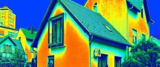
Fig.2 Thermal imaging of building heat losses
The materials of the enclosing structures prevent the penetration of heat from the premises outside in winter and the penetration of heat into the premises in the summer, because the selected materials must have certain thermal insulation properties, which are indicated by a value called heat transfer resistance.
The resulting value will show what the real temperature difference will be when a certain amount of heat passes through 1 m² of a specific building envelope, as well as how much heat will be lost through 1 m² at a certain temperature difference.
The main places of heat transfer in the house
To determine the level of heat loss, not only the climatic conditions of the area are taken into account, but also the location of the building in relation to the cardinal points. People's comfort depends on the design features of the building, the quality of insulation of external walls, and facade finishing.
When estimating the volume of waste heat, the following factors are also taken into account:
- Possible heat loss due to infiltration through “breathing” walls, closed windows and doors.
- Leakage of warm air through internal enclosing structures - walls, ceilings, floors.
- Heat loss for ventilation. When placing it, calculate the volume of ventilated air.
The calculation of heat loss through plastic windows is also affected by the number of double-glazed windows in them - the more there are, the lower the leakage.
Average calculation and accurate
Taking into account the described factors, the average calculation is carried out according to the following scheme. If per 1 sq. m requires 100 W of heat flow, then a room of 20 sq. m should receive 2,000 watts. A radiator (popular bimetallic or aluminum) of eight sections produces about 150 W. Divide 2,000 by 150, we get 13 sections. But this is a rather enlarged calculation of the thermal load.
The exact one looks a little scary. Nothing complicated really. Here's the formula:
- q1 – type of glazing (regular = 1.27, double = 1.0, triple = 0.85);
- q2 – wall insulation (weak or absent = 1.27, wall laid with 2 bricks = 1.0, modern, high = 0.85);
- q3 – ratio of the total area of window openings to the floor area (40% = 1.2, 30% = 1.1, 20% - 0.9, 10% = 0.8);
- q4 – street temperature (the minimum value is taken: -35 o C = 1.5, -25 o C = 1.3, -20 o C = 1.1, -15 o C = 0.9, -10 o C = 0.7);
- q5 – number of external walls in the room (all four = 1.4, three = 1.3, corner room = 1.2, one = 1.2);
- q6 – type of calculation room above the calculation room (cold attic = 1.0, warm attic = 0.9, heated residential room = 0.8);
- q7 – ceiling height (4.5 m = 1.2, 4.0 m = 1.15, 3.5 m = 1.1, 3.0 m = 1.05, 2.5 m = 1.3).
Using any of the described methods, you can calculate the heat load of an apartment building.
Selecting a calculation method
Sanitary and epidemiological requirements for residential buildings
Before calculating the heating load using aggregated indicators or with higher accuracy, it is necessary to find out the recommended temperature conditions for a residential building.
When calculating heating characteristics, you must be guided by SanPiN 2.1.2.2645-10. Based on the data in the table, it is necessary to ensure the optimal heating operating temperature in each room of the house.
The methods used to calculate the hourly heating load may have varying degrees of accuracy. In some cases, it is recommended to use fairly complex calculations, as a result of which the error will be minimal. If optimizing energy costs is not a priority when designing heating, less accurate schemes can be used.