It is impossible to competently design a house without thermal engineering calculations. They are needed to create comfortable living conditions in the building, especially in winter. During calculations, the energy characteristic is always determined - thermal power. It is needed to draw up a heat balance and determine the efficiency of the heating system. Read and find out what it is, the influencing factors on its calculation and calculation options.
Comfort in the home largely depends on the power of heating devices Source mvestnik.ru
Thermal loads
Thermal load is the amount of heat to replenish the heat loss of a building (room), taking into account the use of heating devices in peak temperature conditions.
Power, the total power of heating devices involved in heating a building, providing a comfortable temperature for living and conducting business activities. The power of the heat sources should be sufficient to maintain the temperature on the coldest days of the heating season.
The heat load is measured in W, Cal/hour, - 1W=859.845 Cal/hour. Calculation is a complex process. It is difficult to do on your own, without knowledge and skills.
Load calculation is a critical stage in introducing a building into a centralized heating network.
The internal thermal regime depends on the design of the building load. Errors negatively affect heat consumers connected to the system. Probably everyone on cold winter evenings, wrapped in a warm blanket, complained about Heating Networks with cold radiators - the result of a discrepancy with actual thermal conditions.
The heat load is added up taking into account the number of heating devices (radiator batteries) to maintain heat, with the following parameters:
- heat loss of the building, which consists of the thermal conductivity of the building materials of the box and the roof of the house;
- during ventilation (forced, natural);
- hot water supply to the facility;
- additional heat costs (sauna, bathhouse, household needs).
With the same requirements for a building, the load will be different in different climatic zones. Affected by: location relative to sea level, the presence of natural barriers to cold winds, and other geological factors.
Pipe diameter
How to find out the minimum value of the internal diameter of the filling pipe or supply pipe to the heating device? Let’s not start getting into the weeds and use a table containing ready-made results for the difference between supply and return by 20 degrees. This value is typical for autonomous systems.
The high flow rate of the coolant should not be more than 1.5 m/s to avoid the appearance of noise; more often they focus on a speed of 1 m/s.
| Inner diameter, mm | Thermal power of the circuit, W at flow rate, m/s | ||
| 0,6 | 0,8 | 1 | |
| 8 | 2450 | 3270 | 4090 |
| 10 | 3830 | 5110 | 6390 |
| 12 | 5520 | 7360 | 9200 |
| 15 | 8620 | 11500 | 14370 |
| 20 | 15330 | 20440 | 25550 |
| 25 | 23950 | 31935 | 39920 |
| 32 | 39240 | 52320 | 65400 |
| 40 | 61315 | 81750 | 102190 |
| 50 | 95800 | 127735 | 168670 |
Let's say, for a 20 kW boiler, the minimum internal filling diameter at a flow speed of 0.8 m/s will be 20 mm.
Please note: the internal diameter is close to the nominal diameter of the metal pipe. Plastic and metal-plastic pipes in most cases are marked with an outer diameter, which is 6-10 mm larger than the inner one. Thus, a polypropylene pipe measuring 26 mm has an internal diameter of 20 mm.
Parameters for calculating thermal loads
The information is provided for informational purposes, for load calculations that are not intended for the design documentation required to connect the building to the central heating network - as a statistical base for heat energy consumption.
Thermal characteristics
It is difficult to make an accurate calculation; it is difficult to take into account the nuances of the building. It is good to use the experience of friends, statistical data of similar objects (heat energy consumption over several years). If not, you will have to master the skill of designing and calculating loads yourself.
- Before making calculations, you need to determine the purpose of the building. Identify and draw up a temperature estimate for the optimal conditions of each room - data can be found in SNiP 2.04.05, DVN V.2.5-39:2008. Contains recommendations on coolant and optimal modes for premises. The correct mode will help in accounting and distribution of thermal energy.
- It is necessary to study the design features of the building, the building materials used, the thickness of the walls, thermal insulation, the type, nature of the roof, attic space, number, area of door and window openings. Each building material has thermal conductivity; you need to know which material is used where, determine the area, and identify the total heat loss of the building.
- Saunas, steam baths, and greenhouses should be included in separate calculations.
- The ventilation system is a significant load on the heating system.
- Intensity of use of premises. Is constant temperature maintenance necessary for living or just for maintenance?
There may be more clarifying factors for load calculation.
We calculate the heat consumption by quadrature
To roughly estimate the heating load, the simplest thermal calculation is usually used: take the outside area of the building and multiply it by 100 W. Accordingly, the heat consumption of a 100 m² country house will be 10,000 W or 10 kW. The result allows you to select a boiler with a safety factor of 1.2-1.3; in this case, the power of the unit is taken to be 12.5 kW.
We propose to perform more accurate calculations that take into account the location of rooms, the number of windows and the region of development. So, for ceiling heights up to 3 m, it is recommended to use the following formula:
The calculation is carried out for each room separately, then the results are summed up and multiplied by the regional coefficient. Explanation of formula symbols:
- Q – required load value, W;
- Spom – square footage of the room, m²;
- q – indicator of specific thermal characteristics, related to the area of the room, W/m²;
- k is a coefficient that takes into account the climate in the area of residence.
For reference. If a private house is located in a temperate climate zone, the coefficient k is taken equal to one. In the southern regions k = 0.7, in the northern regions values of 1.5–2 are used.
In an approximate calculation based on the total quadrature, the indicator q = 100 W/m². This approach does not take into account the location of the rooms and the different number of light openings. The corridor located inside the cottage will lose much less heat than a corner bedroom with windows of the same area. We propose to take the value of the specific thermal characteristic q as follows:
- for rooms with one external wall and a window (or door) q = 100 W/m²;
- corner rooms with one light opening - 120 W/m²;
- the same, with two windows – 130 W/m².
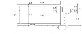
How to correctly select the value of q is clearly shown on the building plan. For our example, the calculation looks like this:
Q = (15.75 x 130 + 21 x 120 + 5 x 100 + 7 x 100 + 6 x 100 + 15.75 x 130 + 21 x 120) x 1 = 10935 W ≈ 11 kW.
As you can see, the refined calculations gave a different result - in fact, 1 kW more thermal energy will be consumed to heat a particular 100 m² house. The figure takes into account the heat consumption to heat the outside air entering the home through openings and walls (infiltration).
System power calculation
There are many correction factors. How did your ancestors calculate the workload, without projects? By trial and error, a large margin was taken into account.
Calculation as a percentage
The main thing in independent calculations is to determine the approximate heat indicator for choosing a source. Need to consider:
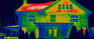
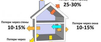
- replenishment of heat in case of losses through walls, roof, windows, doors;
- heating for compensation when ventilating indoor air;
- heating of specific objects;
- reserve for extreme situations: abnormally cold winter, construction of additional utility facilities.
The calculated load, taking into account the factors, is sufficient to fully heat buildings. In other cases, there are design bureaus where specialists bear personal responsibility for the developed thermal systems
Video description
A specialist talks about the need to accurately calculate heat losses in this video:
Calculation of heat losses through walls and roof
To calculate the heat that a building loses through a specific building structure, a special formula is used. Before using it, the area of the external fence of the building is calculated (A, m²), the standard temperature inside the room and its minimum value outside for the coldest five-day period of the year for the area where the house is built are determined. The formula also uses the heat transfer resistance of the building's external structure. This parameter is usually denoted by the letter R and measured m²*℃/W.
Formula for calculating heat loss through the roof and walls Source ppt-online.org
Calculation features
To independently prepare a load calculation, you will need documentation.
Formula
- SP 131.13330.2012 Construction climatology;
- Methodology for determining the amount of thermal energy and coolant in municipal heating water systems dated May 6, 2000, No. 105;
- GOST 12.1.005-88 “General sanitary and hygienic requirements for air in the working area”;
- GOST 30494-2011 “Residential and public buildings. Indoor microclimate parameters."
The standards contain parameters for calculating the building load, except:
- Building location;
- The volume of the building, calculated along the external perimeter. The parameter can be taken from the technical documentation for the house (technical passport) and determined independently by measuring it.
- The purpose of the house being put into operation (residential, administrative, medical, sanatorium).
- The height for calculating the infiltration coefficient is an indicator of resistance to wind and thermal loads.
Calculation methods
There may be several determination methodologies. You can find out the thermal load in the following ways:
- Method for determining the heat loss of an object.
The building materials from which the walls and roof are made are determined; the quantity, area of door and window openings, and number of floors are taken into account. The coefficients are taken and the total value of heat loss is calculated.
- A calculation method that takes into account the required power of heating and ventilation devices necessary to maintain the temperature regime.
- Method using aggregated heat loss values.
Heat consumers
Types of thermal loads for calculations
Thermal loads are not a constant value and can fluctuate up or down. It can be roughly divided:
- The load depends on the heating season - the difference is up to 40%.
Depending on the external temperature, the indicator can vary significantly. The temperature difference is significantly different in winter and autumn-spring. The load changes depending on the time of day; differences arise from the operation of the ventilation system.
- The load depends on the IN radiation. Not just radiators, any equipment that produces heat. There is no need to dump natural radiation entering the building through window openings.
- Additional heat sources. The main source is people, the more, the more heat they emit.
Additional heating - external factors: air flows entering the room through cracks.
Changes in the thermal conditions of the room entail changes in the temperature of the coolant (T. return), which affects the performance of the system.
Briefly about the main thing
The amount of heat required is always calculated when heating is created. After all, this is the only way to create an effective heating system for your home. Using this parameter, the rate of transfer of thermal energy from heating equipment and its consumption by a specific object is determined. The value of this characteristic depends on the volume of the house, the climatic zone of its location, the thermal conductivity of materials, the size of radiators, internal and external temperatures.
The required thermal energy can be calculated using a simplified or exact method. Methods based on aggregated data involve calculation by area or volume. For a more accurate calculation, the total heat loss of the object through all external building structures is determined. Additionally, the heat consumed for ventilation is taken into account.
Power regulators
RTN (thermal load regulator) – elements for regulating heating boilers for domestic and industrial use. The devices stabilize the operation of heat sources and maintain the temperature of the coolant in the system at specified values.
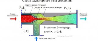
Heating network wiring
With the help of RNG, you can most accurately set the required temperature and optimize the heating system. The heating boiler operates evenly, eliminating temperature surges in the system.
It is difficult to adjust the mode yourself; it is better to contact a specialist.
Conclusions and problem solving
As you can see, the available methods for calculating the thermal load with your own hands give very significant errors. Fortunately, excess boiler power won't hurt:
- Gas boilers operate at reduced power with virtually no drop in efficiency, while condensing boilers even reach the most economical mode at partial load.
- The same applies to solar boilers.
- Electric heating equipment of any type always has an efficiency of 100 percent (of course, this does not apply to heat pumps). Remember physics: all power not spent on mechanical work (that is, moving mass against the gravity vector) is ultimately spent on heating.
The only type of boilers for which operation at a power less than rated is contraindicated is solid fuel. The power control in them is carried out in a rather primitive way - by limiting the flow of air into the firebox.
What is the result?
- If there is a lack of oxygen, the fuel does not burn completely. More ash and soot are produced, which pollute the boiler, chimney and atmosphere.
- The consequence of incomplete combustion is a drop in boiler efficiency. It’s logical: after all, fuel often leaves the boiler before it burns.
Limiting the power of a solid fuel boiler affects its efficiency.
However, here too there is a simple and elegant way out - including a heat accumulator in the heating circuit. A thermally insulated tank with a capacity of up to 3000 liters is connected between the supply and return pipelines, disconnecting them; in this case, a small contour is formed (between the boiler and the buffer tank) and a large one (between the tank and the heating devices).
How does this scheme work?
- After lighting, the boiler operates at rated power. At the same time, due to natural or forced circulation, its heat exchanger transfers heat to the buffer tank. After the fuel has burned out, circulation in the small circuit stops.
- For the next few hours, the coolant moves along a large circuit. The buffer tank gradually releases the accumulated heat to radiators or water-heated floors.
As you can see, in this case, the boiler power reserve will have an exclusively positive consequence - a longer period of time between kindlings (
Loads on DHW, ventilation
Heating point
Fresh air is necessary for human life, which is why ventilation systems are required. However, ventilation significantly increases heat loss.
Loss compensation significantly increases the overall thermal load. Taken into account at the design and calculation stage. Formula:
Q=qV(tn.-tv.)
V is the total volume of the building along the external contour,
t (n and v) – external, internal air temperature;
q – specific value.
Formula for calculating the hot water supply to a building:
Q=0.042rV*∆ T * P * G
∆T – water temperature difference;
P – number of consumers (sinks);
B – load ratio according to GOST;
r is the density of water.
