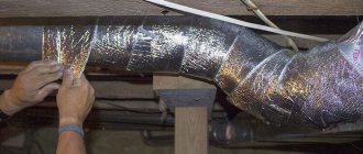
- The duct type affects the coefficient of friction only in those ducts that have been fully stretched (0% compression).
- The degree of compression has a great influence on the coefficient of friction. 5% compression can result in a doubling of the coefficient of friction. And then the influence of the type of air duct turns out to be negligible.
- The influence of the duct diameter (102 mm - 305 mm), air speed (2 m/s - 6 m/s) and flow direction on the friction coefficient can be neglected.
- The resistance coefficient greatly depends on the type of duct.
The results of the study are shown in pressure drop graphs.
1. Introduction
The pressure drop in a duct consisting of one or more straight sections and several bends depends, among other things, on the friction coefficients of the duct and the resistance coefficients of the bends.
To determine the pressure drop in the duct, you need to know these coefficients. The influence of certain parameters on these coefficients has been measured by TNO.
When studying air ducts, the influence on the friction coefficient of the following parameters was assessed:
- Duct type
- Duct diameter
- Compression ratio
- Flow direction
- Air speed
When studying bending, the influence on the resistance coefficient of the following parameters was assessed:
- Knee shape
- Duct type
A measuring stand was used during the research.
Next, we will consider the effect of the diameter of the duct, the roughness of the internal walls of the duct and the Reynolds number on the friction coefficient, and then the equivalent length of the bends will be considered.
2. Pressure drop
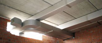
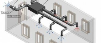
As a rule, the installed air duct has several straight sections and several bends. When gas flows through such an air duct, a pressure drop will be observed at each straight section and at each bend. To determine the fan pressure, it is necessary to determine the pressure drop on each straight section and on each bend of the duct.
Straight duct section
The following follows from this formula:
- The pressure drop is proportional to the friction coefficient.
- The pressure drop is proportional to the gas density.
- The friction coefficient decreases slightly with increasing Reynolds number (Re = UD/v).
- The friction coefficient decreases as the relative roughness k/D decreases.
It follows that:
- The friction coefficient decreases slightly with increasing speed (due to increasing Reynolds number).
- The friction coefficient decreases with increasing diameter if the wall roughness remains the same (due to an increase in the Reynolds number and a decrease in the relative roughness).
The roughness of the walls is determined
- duct type;
- compression ratio.
The effect of the duct on the coefficient of friction was determined at 0% compression, so the actual length of the duct was equal to the maximum length.
Bends
The pressure drop at a duct bend is greater than the pressure drop in a welded elbow with the same diameter and radius of curvature, since friction losses in the bend are much greater. In a metal elbow, the inner wall is smooth, unlike a duct bend, especially if the inside of the bend is highly compressed. In this regard, the surface streamlined by the flow becomes smaller, and the flow speed increases.
Equivalent length
The equivalent bend length is the length of the straight section, the pressure drop across which is equal to the pressure drop across a given bend.
The equivalent lengths of the DFA 102 mm ducts tested were determined using this formula.
Digital library
Life safety in the technosphere / Habitat protection systems / 1.5.5 Calculation of channels and air ducts
In duct natural exhaust ventilation systems
air moves in ducts and ducts under the influence of natural pressure resulting from the difference in pressure between cold external and warm internal air.
Natural pressure
(Dre) is determined by the formula:
Dре = hig (rn – rв), (1.5)
where hi is the height of the air column, taken from the center of the exhaust opening to the mouth of the exhaust shaft, m; rн, rв – density of external and internal air, respectively, kg/m3.
Estimated natural pressure
for ventilation systems of residential and public buildings according to /36/ is determined for an outside air temperature of +5 °C. It is believed that at higher outside temperatures, when natural pressure becomes very insignificant, additional air exchange can be obtained by opening vents, transoms, and sometimes window frames more often and for a longer time.
Analyzing expression (1.5), the following practical conclusions can be drawn:
1) the upper floors of the building, compared to the lower ones, are in less favorable conditions, since the available pressure here is less;
2) natural pressure becomes high at low outside temperatures and decreases noticeably in the warm season;
3) cooling the air in the air ducts (channels) entails a decrease in the effective pressure and can cause condensation with all the ensuing consequences.
In addition, from expression (1.5) it follows that natural pressure does not depend on the length of horizontal air ducts, while to overcome resistance in short branches of air ducts, of course, less pressure is required than in branches of considerable length. Based on technical and economic calculations and operating experience of exhaust ventilation systems, their radius of action (from the axis of the exhaust shaft to the axis of the most distant hole) is allowed to be no more than 8 m.
For normal operation of the natural ventilation system, the following conditions must be met:
S(Rlb + Z)a = Dpe,
where R – specific pressure loss due to friction, Pa/m; l – length of air ducts (channels), m; Rl – pressure loss due to friction of the design branch, Pa; b – correction factor for surface roughness; Z – pressure loss due to local resistance, Pa; a – safety factor equal to 1.1…1.15; Dpe – available pressure, Pa.
The calculation of air ducts (channels) should be preceded by the following calculation and graphic work:
1) determination of air exchanges;
2) layout of ventilation systems;
3) graphic representation of system elements on floor plans and attics;
4) drawing axonometric diagrams of all elements of the system;
5) aerodynamic calculation of air ducts.
1.
Air exchanges for each room are determined by multiplicities (according to the building codes and regulations of the relevant building) or by calculation. During this work, a special form is filled out (Table 1.7).
Table 1.7
Air exchange of building premises
| Number of the room | Purpose | Size premises, m | Room volume | Air exchange rate | Air exchange, m3/h | Channel cross-section dimensions, mm | Number of channels | ||||||||
| Length | Width | Height | Inflow | Hood | Inflow, | Installation number | Exhaust, m3/h | Installation number | Inflow | Hood | inlet | exhaust | |||
| 1 | 2 | 3 | 4 | 5 | 6 | 7 | 8 | 9 | 10 | 11 | 12 | 13 | 14 | 15 | 16 |
2.
Only premises of the same name or similar in purpose are combined into one system. The ventilation systems of apartments, dormitories and hotels are not combined with the ventilation systems of kindergartens and nurseries, retail and other institutions located in the same building. Sanitary facilities in all cases are served by independent systems and, with five toilets or more, are equipped with mechanical stimulants.
In kindergartens and nurseries, it is recommended to install natural ventilation exhaust systems, independent for each group of children, combining rooms taking into account their purpose. In smoking rooms, as a rule, mechanical ventilation is provided. It is recommended to combine exhaust hoods from rooms in a residential building with windows facing one side into one system.
3.
The floor and attic plans graphically depict the elements of the ventilation system (ducts and air ducts, exhaust openings and louvers, exhaust shafts). The amount of air removed through the duct is indicated opposite the exhaust openings of the premises. It is recommended to designate transit channels serving the premises of the lower floors with Roman numerals (I, II, III, etc.). All ventilation systems must be numbered.
4.
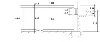
Draw axonometric diagrams of the exhaust ventilation system in lines (Fig. 1.6) or, better yet, with an image of the external outlines of all elements of the system. On the diagrams, the section number is placed at the leader line (possibly in a circle), the section load (air flow) in cubic meters per hour (m3/h) is indicated above the line, and the section length in meters is indicated below the line.
5.
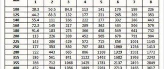
Aerodynamic calculations of air ducts (channels) are performed according to the table or nomograms (Fig. 1.7) compiled for steel air ducts of circular cross-section at rв = 1.205 kg/m3, tв = 20 °С. The quantities L, R, v, hv and d are interconnected in them.
| Table 1.8 Friction equivalent diameters for brick channels | ||
| Size, in bricks | Area, m2 | dE, mm |
| 1/2 x 1/2 | 0,020 | 140 |
| 1/2 x 1 | 0,038 | 180 |
| 1 x 1 | 0,073 | 225 |
| 1 x l ½ | 0,110 | 320 |
| 1 x 2 | 0,140 | 375 |
| 2 x 2 | 0,280 | 545 |
| Note. For channels with a square cross-section, the friction equivalent diameter (dе) is equal to the side of the square channel (a). | ||
When calculating rectangular air ducts, it is necessary to first determine the corresponding value of the equal (equivalent) diameter, i.e., the diameter of the round air duct at which, for the same air speed as in a rectangular air duct, the specific pressure loss due to friction would be equal to ( table 1.8).
The diameter of the equivalent air duct is determined by the formula:
de = 2 ab / (a + b),
where a, b are the dimensions of the sides of the rectangular air duct, m.
If the air ducts have a rough surface, then the coefficient of friction for them, and, consequently, the specific pressure loss due to friction will be correspondingly greater than indicated in the nomogram for steel air ducts. The calculation takes into account the roughness coefficient (β) according to table. 1.9.
Methodology for calculating air ducts (channels)
natural ventilation systems can be presented in the following form:
1) for given volumes of air to be moved through each section of the channels, the speed of its movement is taken;
2) the cross-sectional area of the channels is preliminarily determined from the volume of air and the accepted speed. Friction pressure losses and local resistances for such channel sections are determined using tables or nomograms;
3) compare the resulting total resistance with the available pressure. If these values coincide, then the previously obtained cross-sectional areas of the channels can be accepted as final. If the pressure loss turns out to be less or more than the available pressure, then the cross-sectional area of the channels should be increased or, conversely, decreased, i.e. proceed in the same way as when calculating the heating system pipeline.
When preliminary determining the cross-sectional areas of the channels of natural ventilation systems, the following air speeds can be set:
ü in vertical channels of the upper floor V = 0.5...0.6 m/s;
ü from each floor below is 0.1 m/s more than from the previous one, but not higher than 1 m/s;
ü in prefabricated air ducts V > 1 m/s;
ü in the exhaust shaft V = 1…1.5 m/s.
Table 1.9
Roughness coefficients of channels (air ducts) made of various materials
| Air speed, m/s | Duct material | |||
| Slag gypsum | Cinder concrete | Brick | Plaster on mesh | |
| 0,4 | 1,08 | 1,11 | 1,25 | 1,48 |
| 0,8 | 1,13 | 1,19 | 1,4 | 1,69 |
| 1,2 | 1,18 | 1,25 | 1,25 | 1,84 |
| 1,6 | 1,22 | 1,31′ | 1,58 | 1,95 |
| 2 | 1,25 | 1,35 | 1,65 | 2,04 |
| 2,4 | 1,28 | 1,38 | 1,70 | 2,11 |
| 3 | 1,32 | 1,43 | 1,77 | 2,2 |
| 4 | 1,37 | 1,49 | 1,86 | 2,32 |
| 5 | 1,41 | 1,54 | 1,93 | 2,41 |
| 6 | 1,44 | 1,58 | 1,98 | 2,48 |
| 7 | 1,47 | 1,61 | 2,03 | 2,54 |
| 8 | 1,49 | 1,64 | 2,06 | 2,58 |
If a ventilation unit with ducts exiting to the roof is being calculated, then the calculation begins from the bottom floor, with a design speed of 1 m/s, and on subsequent floors the speed is reduced if the available natural pressure is insufficient.
If, when calculating air ducts, the cross-sectional area of the channels is specified and the hourly air flow rate is known, then the speed (V) is determined by the formula:
V = L / 3 600 f, (1.6)
where L is the ventilation air flow rate for the design area, m3/h; f – cross-sectional area of the channel or air duct, m2.
The pressure loss due to local resistance is equal to:
Z = S x hV,
where Sx is the sum of local resistance coefficients; hV – dynamic pressure, Pa.
Dynamic pressure (hV) is determined using the additional scale of the nomogram for calculating air ducts (shown on the right side of the nomogram).
Local resistance in the ventilation system in many cases significantly depends on the ratios of the sizes of the fittings and other ventilation elements, and in tees-crosses - on the ratios of the connected or divisible flows. Numerically approximate values of local resistance coefficients are given in /44/.
6. Compression
The compression of the duct has a great influence on the coefficient of friction. It has been found that if the duct is compressed by just 5%, this already causes approximately a doubling of the coefficient of friction.
It is obvious that the roughness of the inner wall of the duct increases greatly, even if the compression is very small. In Fig. Figure 4 also shows that during compression the coefficient of friction increases almost linearly until the compression exceeds 20%. For every percentage compression, the coefficient of friction increases by approximately 0.01. If the duct is compressed by only 3%, the coefficient of friction will increase by approximately 0.03. The magnification is the same for the five duct types tested, despite the differences between them.
7. Friction coefficient
From the above it follows that the influence of the duct diameter, air speed and flow direction on the friction coefficient can be neglected. It has also been found that the degree of compression has a greater influence than the type of duct. To determine the compression ratio using formula 4, information about the maximum length of the corresponding air duct is required. However, the maximum length depends on the amount of force applied to determine that length. In addition, a certain force in a small diameter duct causes greater tensile stresses than in a larger diameter duct with the same wall thickness. In this study, friction coefficients for various types of ducts were used only for ducts stretched to the same length as the duct being tested.
see also
- Do-it-yourself ventilation on the balcony
- Crankcase ventilation valve accent tagaz
- Cleaning the ventilation system
- Plastic pipes for ventilation dimensions
- Ventilation in the waiting room
- How to properly ventilate a chicken coop
- Ventilation in a timber bath
- Supply ventilation valve KPV 125
- Industrial premises ventilation project
- Aluminum profile for ventilation
- Do-it-yourself ventilation in the steam room diagram
5.8. Bending resistance coefficient
It has been established that air speed has almost no effect on the value of the drag coefficient. Increasing the radius of curvature of a 90° bend leads to a decrease in the drag coefficient. However, a 180° bend shows an increase in resistance.
This goes against all expectations. This is probably due to the slight difference in surface roughness between these bends, since the degree of compression will be different for them. The reason may also be differences in the flow pattern at these bends. Duct type appears to have only a minor effect on the R-value of these bends. This was to be expected. The inner side of the bend is always compressed in such a way that its roughness is much greater than the roughness of the air duct (maximum stretched).
VIBRATIONS IN TEXTILE AIR DUCTS
The emergence of vortex zones, described earlier, can lead to vibrations of the surfaces of air diffusers. Turbulence in the system can occur:
· after air overcomes the throttles or fan;
· due to the flow overcoming bends, turns and other shaped parts;
· at extremely low static pressure, unable to affect loss compensation;
· in case of discrepancy between the dynamic and static pressure in the textile air duct.
To obtain laminar air flow, it must be created using stabilizers. It is important to remember that the use of equalizers reduces hose vibration, but creates pressure losses that must be taken into account when designing the system.