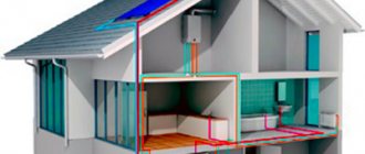
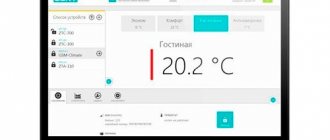
A program for designing building heating systems according to domestic standards, which combines the calculation and graphic parts of the project.
Specialized software Project Studio CS Heating is intended for designing heating systems for buildings and structures. The program presents the calculation (hydraulic and thermal calculation of a water heating system according to SNiP 41−01−2003) and graphic parts of the design section “Heating” and automatic specification.
As an application to AutoCAD, Project Studio CS Heating allows you to load the architectural background of any format supported by this system (*.dwg files, bitmaps, OLE objects, etc.), and when using Autodesk Architectural Desktop or AutoCAD Architecture - work with *.dwg files created in these programs.
Application area
The Project Studio CS Heating software product includes specialized tools for a heating system design engineer. From the created model of heating systems, the user receives almost all the necessary documentation:
- floor plans of heating systems;
- axonometric diagrams of heating systems;
- equipment specification;
- explication of premises;
- general project report;
- list of heating devices;
- list of circulation rings;
- statement of hydraulic calculation of circulation rings;
- report on fittings settings;
- statement of thermal calculation of heating devices;
- three-dimensional solid model of the heating system.
It should be noted that a three-dimensional model of the system, axonometric diagrams, equipment specifications and report sheets are generated automatically.
Flow
Flow
– a program for calculating heating systems, presented by a domestic developer of specialized software.
This software package allows you to create and simulate a working diagram of a heating system of any configuration, including underfloor heating. The features of this software are:
- Output the result for viewing and editing in AutoCad or Word.
- The ability to carry out all the calculations necessary to create a competent RM thanks to a rich toolkit.
- Availability of databases with characteristics of equipment and components from several manufacturers (including domestic ones).
- Possibility of creating CO schemes based on several types of coolant.
User-friendly interface
The Project Studio CS Heating program has a familiar interface, which allows you to minimize the time it takes to implement it. The user works with standard drop-down menus, toolbars, and the command line. In addition, Project Studio CS Heating implements service functions for creating models of heating systems, such as a context menu, tracking and object snapping modes, etc.
Tools in the Valtec Main Menu
Valtec, like any other program, has a main menu at the top.
We click on the “File” button and in the submenu that opens we see standard tools known to any computer user from other programs:
The “Calculator” program built into Windows is launched to perform calculations:
Using the "Converter" we will convert one unit of measurement to another:
There are three columns here:
On the far left we select the physical quantity we are working with, for example, pressure. In the middle column is the unit from which you need to convert (for example, Pascals - Pa), and in the right column - into which you need to convert (for example, to technical atmospheres). In the upper left corner of the calculator there are two lines, in the upper one we will enter the value obtained during the calculations, and in the lower one we will immediately display the conversion to the required units of measurement... But we’ll talk about all this in due time, when it comes to practice.
In the meantime, we continue to get acquainted with the “Tools” menu. "Form generator":
This is necessary for designers carrying out custom projects. If we do heating only in our house, then we don’t need the “Form Generator”.
The next button in the main menu of the Valtec program is “Styles”:
It controls the appearance of the program window - it adapts it to the software that is installed on your computer. For me, this is an unnecessary gadget, because I am one of those for whom the main thing is not “checkers”, but getting there. And you decide for yourself.
Let's take a closer look at the tools located under this button.
In “Climatology” we select the construction area:
Heat loss in a house depends not only on the materials of the walls and other structures, but also on the climate of the area where the building is located. Consequently, the requirements for the heating system depend on the climate.
In the left column we find the area in which we live (republic, region, region, city). If our settlement is not here, then choose the nearest one.
"Materials". Here are the parameters of different building materials used in house designs. That is why, when collecting initial data (see previous materials on design), we listed the materials of walls, floors, and ceilings:
Openings tool. Here is information on door and window openings:
"Pipes". Here you can find information about the parameters of pipes used in heating systems: internal and external dimensions, resistance coefficients, roughness of internal surfaces:
We will need this for hydraulic calculations - to determine the power of the circulation pump.
"Coolants". Actually, there is nothing here except the characteristics of those coolants that can be poured into the heating system of a house:
These characteristics are heat capacity, density, viscosity.
Water is not always used as a coolant; it happens that antifreeze, popularly called “anti-freeze,” is poured into the system. We’ll talk about choosing a coolant in a separate article.
“Consumers” are not needed to calculate the heating system, since this tool is for calculating water supply systems:
"KMR" (local resistance coefficients):
Any heating device (radiator, valve, thermostat, etc.) creates resistance to the movement of the coolant, and these resistances must be taken into account in order to correctly select the power of the circulation pump.
"DIN devices". This, like “Consumers”, applies more to water supply systems:
Smart objects Project Studio CS Heating
All objects of Project Studio CS Heating (pipelines, heating devices, pipeline fittings, etc.) are intelligent. Any of the objects has properties characteristic of this element, which can be edited during the design process. For each group of elements, these properties have certain characteristics. For pipelines, you can select the assortment and standard size, for heating devices - the standard size or number of sections and piping characteristics, taking into account the fittings, and for pipeline fittings - the assortment and standard size.
HERZ calculation program HERZ official website of HERZ Armaturen in our country
We also inform you that the HERZ valve database in the RAUCAD program has been updated. If you have any questions about obtaining a new database, please contact the engineer of the technical support group of the internal engineering systems department, Moscow, tel. (ext. 203).
HERZ CO program
The HERZ CO program is needed for hydraulic calculations of single- and two-pipe heating systems and cooling, during the design of new systems, as well as for regulating existing ones in reconstructed buildings (for example, after insulating a building), it has the ability to calculate systems where the heat carrier is glycol mixtures.
The program makes it possible to perform all hydraulic calculations of equipment, within the framework of which:
diameters of pipelines are selected; water flow in the designed equipment is analyzed; pressure losses in the equipment are determined; the hydraulic resistance of the circulation rings is determined, taking into account the gravitational pressure associated with cooling of water in pipelines and heat consumers; settings of pressure difference regulators installed in places selected by the designer (base of risers, branches, etc.) are selected; the required authorities of thermostatic valves are taken into account; excess pressure in the circulation rings is reduced by selecting valve presets; The need to equip an appropriate hydraulic resistance in the area with the heat consumer is taken into account.
The program uses many solutions to make work easier and better. The most important of them are:
- graphical data entry process;
- presentation of calculation results on diagrams and floor plans;
- a developed contextual help system that provides information both about individual program commands and a hint regarding the entered data;
- multi-window environment, it allows you to simultaneously view many types of data, results, etc.;
- usual cooperation with printer and plotter, function of previewing pages before printing and outputting to plotter;
- luxurious diagnostics of errors and the function of their automated search, both in the table and in the diagram;
- quick access to catalog data of pipes, radiators and fittings.
HERZ OZC program
The HERZ OZC program is used to determine the estimated heat losses of individual rooms in a building, as well as the entire structure. The calculation is carried out in accordance with the appropriate standards. The program does:
- calculation of heat transfer coefficients for walls, floors, roofs and ceilings between the top floor and the attic;
- calculation of heat loss for individual premises;
- calculation of heat loss of the entire building.
The program uses many solutions to make work easier and better. The most important of them are:
- developed help system;
- luxurious catalog of materials for construction;
- function of automated determination of resistance to heat transfer, resistance of air layers of floors between the top floor and the attic, soil resistance;
- function for automated creation of the next floors, copying of rooms, and also selection of rooms, for example, if while entering data about a room it is necessary to call another room;
- option for automated distribution of heat losses from a room with a small need for heating capacity (for example, a corridor) to adjacent rooms, which provides the opportunity to directly transfer calculation results to the HERZ CO program
The program provides the opportunity to carry out calculations of heat losses of huge buildings.
The following are restrictions regarding the data:
Limit number of defined fences: 16300 Limit number of layers in one fence: 16300 Limit number of rooms: 16300 Limit number of fences in one room: 16300
The results of heat loss calculations are the output data for the HERZ CO program used for designing district heating systems.
Open Databases
The Project Studio CS Heating database contains about 6,000 elements of heating systems. The most popular domestic and foreign manufacturers of heating equipment in Russia are presented, such as Honeywell, Danfoss, Zetkama, VAN-TUBO, Wilo, Grundfos, OJSC SANTEKHPROM, Global, Giel, etc.
All Project Studio CS Heating databases are open for user addition. At the same time, to create new equipment or edit existing equipment, there is no need to have programming skills. The ability to work in a simple spreadsheet editor is enough.
Working with floors, rooms and risers
It is possible to download rooms via IFC format. Also, the engineer can independently determine the contours of the room in both automatic and manual modes. You can automatically number rooms if this has not been done previously. And all characteristics and data for all floors and rooms are displayed in one dialog box Building/object model
. Here it is also possible to change the characteristics (properties) of each floor or room - now there is no need to open each drawing separately.
The Interfloor Connections Wizard is used to view and analyze all designed risers in a building and edit their properties.
About special programs for calculations
Oventrop CO program
This is an absolutely free program that is widely used to calculate a country house. You just need to first set all the necessary settings and specify heating devices and pipes - then you can easily develop new systems. Moreover, if you wish, you can adjust the existing system. This is done as follows: the power of existing devices is selected in accordance with the requirements of the heated building.
Both design methods are perfectly combined in a single software, which makes it possible to create new designs and adjust old ones. Regardless of the method, the program itself selects the fitting settings. Regarding the calculations that interest us, Oventrop CO provides simply unlimited possibilities - from analyzing coolant flow to pipe diameter. All information is displayed in the form of pictures, tables or diagrams.
HERZ CO program
Another representative of free programs that allows you to calculate any kind of heating system. The utility is characterized by the fact that it allows such calculations to be made even in new or recently reconstructed facilities in which the coolant is glycol. It meets all international requirements, therefore, it has all the necessary certificates.
Below are the main opportunities that the German HERZ CO can provide you with
- Select the pipeline diameter.
- Reduce the pressure in the circulation rings by automatically selecting valve parameters.
- Set up pressure difference “regulators”.
- Take into account the necessary parameters of thermostatic valves.
- Analyze future coolant flow, as well as determine the pressure drop in the system.
- Calculate the hydraulic resistance of the circulation rings.
To make it more convenient for you to use the program, all information can be entered graphically. As a result, the utility will give you a floor plan of the building.
Important information! Another distinctive feature of the program is the so-called contextual help. It makes it possible to learn more about the entered command or any indicator.
It is also possible to open several windows at once (which is very rare for this kind of product), so you can study several types of information at the same time. It is possible to work with printers and plotters - it is extremely simply organized, each sheet that is planned to be printed can be previewed.
Hydraulic and thermal calculations. Formation of a three-dimensional solid model of the heating system
When performing calculations, the program creates a complete three-dimensional model of the heating system. The ability to view calculated parameters in network sections has been implemented. At the sections, the heat load, coolant flow rate, movement speed, pressure loss in pipes and local resistances are calculated, and based on the results of these calculations, the diameter of the pipes and the number of radiator sections are selected.
On the properties page Heating system login
you can see a list of rings. In addition, it is possible to visualize the ring in the calculation model. The difference in the alignment of the secondary rings with the main ring is also shown. This allows you to see the rings and find the right place to install the balancing fittings for linking the secondary rings with the main one.
Project Studio CS Heating. Properties of the system
Duct selection program Ducter 2.5
Ducter 2.5
This program for selecting ventilation equipment calculates the diameters of air duct sections. The user enters the maximum values of flow velocity in the air ducts, height differences when calculating natural ventilation or the CMC of the segment. Based on this information, the program selects ventilation equipment of standard diameter in accordance with VSN 353-86 linearly. Thus, the final decision on the diameter remains with the specialist.
If an air duct with non-standard parameters is needed, the program will also help: one parameter is entered, the rest are selected. The selection step is set in the settings.
You can set one of several options for displaying the dimensions of each area.
Program versions from Ducter 3 and higher for selecting equipment will help you fully calculate the entire ventilation system.
Decor
The Project Studio CS Heating program fully complies with the requirements of domestic regulations. All tabular forms comply with GOST 21.602−2011 and GOST 21.110−2013. The placement of the frame with the main inscription on the drawing is carried out in accordance with GOST R 21.1101−2013.
The program implements the following functionality: slope (information is taken from the pipeline), elevation mark (automatically reading the real height of the object), text element (insertion of pipeline designations T1 and T2 into pipes) and a special leader.
Data Consistency
To coordinate data in Project Studio CS Heating, a specialized Project Manager is used. All drawings, specifications and other project documents are guaranteed to refer specifically to the current Project Studio CS Heating project. This allows you to obtain accurate equipment specifications. In addition, the equipment specification always corresponds to the current state of the heating system model.
It is also possible to obtain floor-by-floor equipment specifications. This is especially important in cases where a large facility is being designed and it is necessary to determine what heating equipment needs to be delivered to a specific floor.
The specification template can be customized, which provides a great advantage in obtaining the documentation required by the user.
Design stages
To create a competent CO it is necessary to perform the following types of work:
- Choose the most suitable heating system for a particular building.
- Create a sketch with tracing of the main pipeline and risers.
- Carry out hydrodynamic thermotechnical calculations for the competent selection of equipment, materials and diameters of the pipeline and other elements of the system.
- Create a design drawing linked to the building layout.
The design of heating and ventilation systems begins with the preparation of technical specifications, which are formed on the basis of site inspection data, measurements and the client’s wishes. After this, the specialist offers the customer the most suitable option (sketch) of the heating system with a full feasibility study. When the possible costs of creating a CO are agreed upon with the customer, his comments and wishes are taken into account, the design specialist proceeds to the most important step - calculations, on the basis of which diagrams of the CO and a plan for laying utilities are drawn up.
After consultation with the client, the specialist draws up a specification of materials, equipment and prepares a package of documents for approval by the relevant authorities. The last stage in creating a project is to engage a subcontractor to perform installation and commissioning work.
UGO table
The program implements automatic generation of a table of UGOs used in the project. The table is generated both for each floor and for the entire project.
The generated table is installed on the active *.dwg file in the CAD workspace.
Why do you need virtual home designers?
First of all, builders, architects and interior designers use software designed for designing models of residential buildings, interior filling of rooms and arrangement of local areas. Program parameters for designing a convenient and comfortable home allow you to make changes, changing the building model, the location of rooms, and correcting defects; on paper this will be much more difficult. Other designer functionality includes:
- Selecting the optimal options for the location of the house on the site.
- Selection of the correct configuration and size of the roof, openings for doors and windows.
- Creation of a unique house model and interior space layout.
- Selection of building materials taking into account the climate, weather and characteristics of a particular region.
- Drawing up interior compositions that will suit all residents of the house.
- Correct location of swimming pools, gazebos, patios, and playgrounds in areas near houses.
- Quickly mastering the skills of working in the program allows novice designers and builders to understand the principles of drawing up drawings and planning rooms.
Using programs for virtual construction of a house model will allow builders who want to build their own housing to save money. Construction can be done by professionals, but it is specialized software that determines exactly what materials are needed for the foundation, walls, roof, and interior floors.
Lists of drawings, documents and quantities of work
It is possible to receive in a semi-automatic mode a list of working drawings of the main set in accordance with GOST 21.101−2020, a list of reference and attached documents in accordance with GOST 21.101−2020 and a statement of the volume of construction and installation work in accordance with GOST 21.111−84. These statements can be output in Word, Excel or AutoCAD.
Reports “Heating devices” and “List of heating devices”
Project Studio CS Heating provides reports “Heating devices” and “List of heating devices” with the ability to display them by floor. This function allows installers to be informed in advance which devices and with what piping will need to be delivered to a certain floor, which will help significantly speed up the installation of the heating system. Reports can be output to Excel.
Equipment layout
The layout (placement) of equipment in three-dimensional space is one of the most critical technical decisions in design. To solve the layout problem, Model Studio CS Heating and Ventilation provides all the necessary tools and functions. They provide ease of use and the ability to check acceptable distances at any time and at any stage of project creation.
The developers have created special tools that greatly simplify the work. An excellent example of such a tool is the 2D to 3D fast transition feature, which allows you to complete a design in a familiar 2D plan while switching to a 3D view at the touch of a button. This feature is especially useful for those who have only recently begun to master 3D design and are still experiencing difficulties in perceiving 3D.
Equipment layout (air supply units) from the database
The main source for placing equipment in the model is the database of products and materials (supplied with the software package). Along with this, it is possible to use ready-made equipment models made in various CAD systems: AutoCAD, nanoCAD, Autodesk Inventor, SOLIDWORKS, KOMPAS and other general-purpose CAD systems (by saving in DWG or DXF 3D format).

