From the author: Hello, dear friends! A home heating system with two boilers is one of the most common situations. Gas and electric boilers provide comfort to households and do not require frequent maintenance, while solid fuel boilers help reduce costs and save the family budget from unnecessary expenses.
How to correctly connect two boilers to one heating system, in series or in parallel, are there any analogues for connecting other types of boilers, and on what principle will the work take place? We will try to answer all these questions in today’s article.
Heating battery installation diagram
The placement of radiators in the heating circuit largely affects the performance of the system.
It is customary to distinguish five main ways of installing batteries:
- the top installation option provides for the supply and drainage of water from the upper points of the pipes;
- with the lower connection method, the coolant enters and exits from the lower connectors;
- The one-sided method of constructing a radiator differs in that water is supplied through the top and drained from the bottom, and all this occurs on one side of the battery;
- with a diagonal connection, the coolant is supplied again from above, and the outlet is from below on the reverse side;
- Another installation method is called spot installation. It is used infrequently, since not any radiator is suitable for its implementation. The coolant inlet and outlet in this case are mounted in one of the four corners of the battery.
When choosing a connection method, it is important to pay attention to the design of the radiator itself, and you need to decide which installation option to use before purchasing the heating device
Switching methods
There are two ways of piping boilers operating in pairs:
- sequential;
- parallel.
When implementing serial piping, the boilers are connected one by one; installation and arrangement of additional nodes and lines is not required. The first device warms it up as the coolant moves, the second one brings the water to the required temperature.
This option is rarely used and only for low-power heaters. It is considered irrational, since it is impossible to dismantle one boiler for repairs without turning off the other. The circuit is inoperative if even one of the two units malfunctions. To modernize and improve efficiency, additional fittings are used and a bypass line is installed.
Serial wiring
With parallel piping, two flow connection points are arranged on the direct coolant supply and on the return. The boilers operate independently of each other. In this case, it is possible to install an automatic control unit and a hydraulic switch.
Parallel harness
Features of electric heating equipment
There is a widespread belief that all types of electric heaters provide savings of about 30-40%, and installation of an electric heating boiler will be as profitable as possible. The values described are large, and in theory they allow you to save a significant amount on heating. As a rule, the reason for such efficiency is given as reduced power - i.e. When calculating a heating system, you need to assume that heating one square meter of room requires about 60 W of energy instead of the required 100 W.
Everything said in the previous paragraph is the erroneous opinion of most users. It is not advisable to compare direct heating devices in terms of efficiency, since they will all be equal. This statement is based on the law of conservation of energy, according to which energy cannot appear out of the blue and disappear into nowhere.
In relation to electric heating devices, this means that all generated energy will be converted into heat. Of course, this phenomenon will be accompanied by certain losses - nevertheless, part of the heat will certainly dissipate in the air and will not be transferred to the coolant. But the volume of losses directly depends on the insulation of the device body, and not on the type of heating equipment. In addition, the heat released outside will directly warm the room where the boiler is installed.
If we look at the problem from the other side, then heating is designed to compensate for heat losses, the amount of which is determined by:
- The quality of building insulation, which is completely independent of the efficiency of the heating boiler;
- The difference in temperature in the house and outside, which also does not depend in any way on the heating equipment used.
To summarize, we can definitely say that the type of heat source has no relationship with the thermal power required to heat the building - which means that the vaunted efficiency of electrical devices is simply absent.
However, this only applies to efficiency - each electrical device has special performance qualities:
- Electric radiators. Such devices load the electrical network evenly, so there are no wiring requirements.
- Induction boilers. Such heating equipment is compact and reliable. The latter quality is due to the fact that there is no heating element in the heat exchanger, and the power controller and coil are located outside, so water does not have any effect on them. In addition, induction boilers can work with any coolant.
- Electrode boilers. Differ in smallest sizes. Such boilers require constant replacement of electrodes, since they dissolve in water over time. Only water containing a certain amount of salts can be used as a coolant.
- Heating element boilers. The main problem of boilers with heating elements is the constant deposition of scale on the heating elements (this factor is irrelevant for closed heating circuits, in which the amount of salts is initially limited). In addition, these devices are quite large in size.
Heating a house with solid fuel and electric boilers - how to do it
Heating a house with a solid fuel boiler is not expensive. But it's troublesome. Electricity, on the contrary, is more expensive, but the most comfortable of all types of energy carriers.
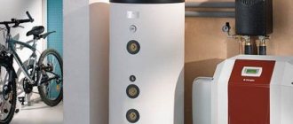
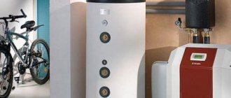
It is a good idea to complement a solid fuel boiler with an electric one, which will greatly simplify the maintenance of heating in the house and the convenience of living. It will be possible not to wake up at night to maintain heating with solid fuel, and also to leave the house for a long time without freezing the building, or simply maintain heat with electricity when there is no time to deal with firewood.
It is advisable to apply for a “night tariff” for electricity supply, which is much cheaper than the daytime tariff. Then the automated electric boiler will be able to heat the house at night, and not just maintain the temperature.
In general, heating with two boilers - solid fuel and electric - is a convenient scheme that is gaining popularity.
It remains to figure out how to heat a home using two heat generators - solid fuel and electric, how to connect correctly, what kind of automation is required so that the operation of the units is coordinated and sequential.
Features of selecting pumps for a scheme with two boilers
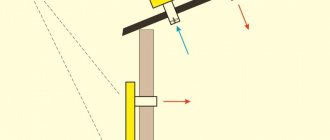
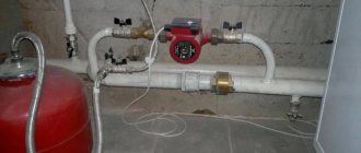
An electric automatic device is equipped with an internal circulation pump, and for solid fuel, this pump must be installed separately, on the return line, after the cleaning filter and expansion tank. Installing this pump on the supply side is not advisable, since if the liquid boils, this pump will not be able to pump steam and the movement of the coolant in the system will stop. Therefore, the boiling process will develop, the temperature in the heat exchanger will increase until either the heat exchanger itself or the connected plastic pipeline fails.
With a solid fuel boiler, the circulation pump is installed on the return line, where it will remain operational even when the liquid boils and prevent the development of this dangerous process.
It is also necessary to pay attention to the pressure that the pumps must develop. As a rule, an electric boiler is equipped with a pump that develops pressure up to 0.4 or a maximum of 0.5 atm, designated, for example, 15/50 (the first number indicates the diameter of the connected pipelines, the second - the pressure). This pump works constantly, driving coolant through the system.
But when two pumps operate simultaneously, if the electric one “overpowers” the solid fuel one, then in the latter the fluid movement will stop or overturn. It will boil, causing a serious accident. If the solid fuel “transmits”, then nothing bad will happen - the automated electric boiler will simply turn off if the temperature of the air or coolant exceeds a certain set value.
Therefore, a device with solid fuel must be equipped with a pump that develops a higher pressure than the pump in an electric boiler, for example 25/60 - 0.6 atm.
The superiority of the solid fuel heat generator pump in terms of pressure is a mandatory condition for switching on according to this scheme.
Connection diagram, check valves
Solid fuel and electric boilers are connected to the main supply and return pipelines in parallel.
But so that the operation of one of them does not affect the operation of the other, check valves are installed at the supply outlet of each of them, after the taps.
Then the injection of liquid by one pump will not affect the other unit, or rather, the jet will not overturn and a small circle of circulation will not occur with the most negative consequences.
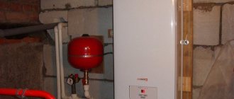
The heating system of a house consisting of two boilers is necessarily equipped with a supply safety group, which includes a pressure gauge, an overpressure emergency valve, and an air bleed valve.
On the return line, a mud filter should be installed with the sludge collector facing down, or at least inclined downwards, as well as a drain valve into the sewer, a system injection valve (connection to the water supply), and an expansion tank that compensates for the increase in pressure when the liquid is heated. Its initial pressure (pumped by an air pump) is usually 1.5 atm. And the volume must be at least 0.1 of the amount of liquid in the system.
Automation means
The solid fuel boiler is equipped with a thermostat, which opens the electrical contacts to control the pump, and its remote sensor is installed at the outlet of the heat exchanger. If the coolant cools down, i.e. If the wood burns out, the thermostat will turn off the pump. Setting - no more than 30 degrees.
Why is it needed? The fact is that there will always be draft through the chimney. When the boiler goes out, it will turn into a good cooling radiator for the coolant, the heat from which is carried away to the sky. If the pump continues to circulate liquid, the coolant will cool rapidly.
When the boiler is melted, the temperature of the liquid at the outlet will quickly increase, and the thermostat will immediately turn on this pump.
Also, this pump must be equipped with an uninterruptible power supply - an uninterruptible power supply. A power outage, even for 15 minutes, can lead to boiling of liquid and destruction of equipment. The movement of fluid should not stop.
For an electric automated device, a room temperature sensor is connected. It registers the air temperature in the room and, in accordance with the automation settings, gives a command to turn on when the air cools down, for example, below 20 degrees, and then to turn off if the temperature, for example, reaches 22 degrees. Those. When the solid fuel boiler starts working, the temperature in the house will rise quickly.
The electric heat generator learns from the air sensor “that it is no longer needed” and stops. As the temperature decreases, when the solid fuel one goes out, the electric one turns on in the mode assigned to it and will maintain the room temperature above 20 degrees C (night mode).
You can make a similar heating scheme for a house with two boilers with your own hands, if you have plumbing skills. And setting up the system will come down to selecting the temperature on the sensors so that the electric one turns on on time, and the solid fuel pump does not turn off before the flame finally goes out.
Ensuring the constant operation of the circuit pump with solid fuel is the priority of using such heat generators in any circuit, including paired not only with an electric, but also with a gas boiler... You can also read about connecting an indirect heating boiler to a solid fuel boiler.
teplodom1.ru
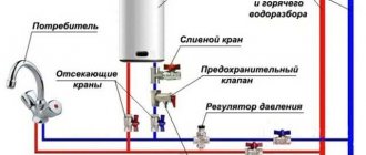
Connecting the boiler to the heating system
Heating systems of modern houses involve the use of boilers. The variety of their types according to the type of raw materials used determines how to install boilers in heating systems
Modern heating equipment can use natural gas, electricity or solid fuel. Installation of heating boilers requires compliance with special requirements for installation and operation.
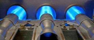
Gas boilers
Heating systems with gas units are popular for use in a private home. Natural gas is an inexpensive and efficient fuel. Of course, this is only possible for those regions where there are main gas pipelines and supplying gas to the house does not cause any difficulties.
At the same time, we must not forget that gas is a highly dangerous environment due to its explosiveness. When choosing gas installations, you need to remember the following differences:
- manufacturer and price segment;
- power consumption;
- number of circuits - single-circuit and double-circuit models;
- type of installation (floor or wall);
- method of cleaning exhaust gases.
Wall-mounted gas installations are very popular - they are easy to install and small in size.
The equipment of such a unit includes a burner, expansion tank, circulation pump (one or more), pressure gauge and thermometer, heat exchanger, exhaust gas removal circuit (natural or forced). For safety, the equipment is equipped with special sensors.
Electric boilers
The main advantage of these compact boilers over units operating on other types of fuel is the complete absence of waste during operation (including the absence of combustion products). It is believed that this is the most environmentally (and aesthetically) clean type of heating in a private home. But, at the same time, perhaps the most expensive. Boilers can be installed on the floor or on the wall. Depending on the type of heating, such settings are:
The design of heating element boilers is quite simple. Several heating elements are placed in a container with distilled water or ethylene glycol-based antifreeze liquid. Depending on the set heating temperature, either all heating elements work, or only part of them. This design is very primitive and is partly considered obsolete.
The operating principle of an induction boiler is based on electromagnetic induction. To put it simply, a core is placed in a dielectric pipe, which is heated by the current of an electric coil around the pipe. The core heats the water that flows through the pipe.
The design is simple, and thanks to this, even very powerful installations are small in size.
The principle of operation of the electrode unit uses a law of physics based on the heating of water due to resistance when an electric current is passed through it. The water must have a special concentration of salts. These devices are safer than the previous two, since if water leaks from the heating tank, the unit automatically stops working.
Solid fuel boilers
Now this equipment is used to heat houses where natural gas heating is not possible. Such boilers operate on various types of solid fuel, but the main type is traditionally firewood. Heating equipment of this type is very similar to a stove, but at the same time meets all safety standards and modern quality requirements for similar installations.
The boilers have in their design a combustion chamber, a heat exchanger, a loading hopper, a chimney, nozzles, a control unit and a hot gas exhaust chamber. Installation of boilers is carried out only on the foundation. They have quite large overall dimensions and weight.
Piping of a wall-mounted double-circuit gas boiler
Modern double-circuit gas boilers are distinguished by their complexity of design. They are ready-to-use devices, ready for integration into heating systems. They usually contain:
- Sealed membrane tanks (the average volume is 8-10 liters, which is quite enough for the heating circuit of a private house);
- Circulation pumps - no need to purchase them separately;
- Safety groups - safety valves, automatic air vents, as well as pressure gauges or thermomanometers are installed here.
Thus, they do not need to purchase additional equipment.
Nevertheless, in the piping schemes of double-circuit heating boilers, additional circulation pumps and air vents can still be used - it all depends on the complexity of the systems being installed.
Water filtration
Water filters can also be classified as piping heating boilers, both electric and gas. They protect equipment from damage resulting from simple blockages. Filters purify water mechanically, trapping small fractions of contaminants, and also provide water softening. The last point is especially important, since high salt content causes clogging of heat exchangers with lime deposits.
The simplest filters are based on ion exchange resin. They replace metal atoms in salts, making the water softer. As a result, the likelihood of limescale deposits on the inside of the boilers is reduced. But before buying filters, it is recommended to check the hardness using special test strips. Membrane filter systems are considered the most reliable, but they are expensive.
Including a filter in the heating boiler piping circuit allows you to reduce the cost of servicing heat exchangers, which involves cleaning them with special liquids - a procedure that is expensive and requires calling a specialist.
Collectors and hydraulic arrows
These devices are used to distribute coolant over several separate circuits. Collectors are installed in the amount of two pieces - one on the supply pipe, and the second on the return pipe. Heating circuits - room radiators, cascades of in-floor convectors, as well as heated floors - are connected to the collector through separate circulation pumps. The cooled coolant returns to the return manifold and is returned through one pipe to the boiler. This heating piping scheme is used in large households.
The hydraulic arrow resembles a manifold in its design, but is connected to two pipes at once. It is installed strictly vertically. In its upper part there is a hot coolant, and in the lower part there is a cooler one. By making inserts, you can distribute the coolant among individual circuits in accordance with its temperature. The radiators are usually connected to the upper part, and heated floors are connected to the lower part.
Recommendations for the selection and installation of trim elements
Before connecting a gas boiler to the heating system, you need to select suitable devices for piping.
When choosing a pump, consider the following parameters:
- Thermal load of the circuit (aka boiler power).
- The difference in coolant temperature in the supply and return pipes.
Units of this type operate very quietly. The degree of pressure of the circulation apparatus can be ignored, since its minimum value of 2 m is quite sufficient. Such a difference moves water in the central heating of an apartment building, where the level of hydraulic resistance is much higher.
The main criterion when choosing a membrane tank is its volume. The optimal figure is 1/10 of the volume of the entire coolant in the house. When calculating it for circuits with aluminum or bimetallic radiators, a coefficient of 15 l/kW is used. The internal pressure inside the container is usually around 1.5 kgf/cm2. To increase it, air is pumped into the gas compartment of the tank through the nipple using a conventional bicycle pump.
The security group includes the following elements:
- Valve. It is regulated according to the upper permissible pressure line of 2.5 kg/cm2.
- Pressure gauge. The instrument scale should record pressure up to 4 kg/cm2.
- Air vent.
Each strapping element has its own installation location:
- Circulation pump. It is best to install it where the coolant has the lowest temperature (in front of the firebox or heat exchanger).
- Security group. The area where pressure begins to increase in the event of circulation cessation (at the outlet of the heat exchanger).
- Expansion tank. Any location in the circuit is suitable for its installation, with the exception of the area in the immediate vicinity of the pump. This limitation is explained by the turbulence created by the impeller, leading to pressure surges inside the tank: this negatively affects the performance of the membrane. Before connecting the wall-mounted boiler, you need to take care of the required space for the expansion tank.
A number of modern models of boiler equipment (new electric, diesel, forced-draft gas heating elements) are equipped with piping built directly into the body. That is why such devices are classified as full-fledged mini-boiler rooms, where the piping includes two ball valves for shutting off the boiler. Thanks to this, when servicing and connecting a floor-standing gas boiler to the heating system, it is possible to avoid significant losses of coolant.
Types of boilers
Types of boiler equipment:
gas. Highly effective, but not worth making at home. The units are classified as high-risk devices. Creation requires skills, technology;
A gas boiler
- electric boilers. Unpretentious in terms of creation and operation. You can make a heating device yourself. There are no increased security requirements;
- liquid fuel The design is simple. Any man can handle the job. Difficulty in adjusting the nozzles;
- solid fuel. Effective and versatile. Easy to use and manufacture. Easily modified and converted to other fuels. The units are also used for heating industrial areas.
Heat-resistant stainless steel has good technical parameters. But she's expensive. Equipment is required to process the material. You can choose cast iron.
When making it yourself, it is better to take sheet steel or a pipe with a thickness of at least 4 mm. The properties of cast iron are good. Simple, easy to process. Regular household devices can handle it.
Electric boiler connection diagram: reliable protection and energy saving
Greetings, comrades! Do you know how to connect an electric boiler to electricity? Are you interested in what elements should the boiler piping include? Today I want to answer these questions in detail and as clearly as possible and tell you which electric boiler connection diagram will allow you to heat your home at minimal cost.
Diagram of an electrical boiler room with an automatic control system for boiler power.
Before undertaking the implementation of any project, you need to clearly formulate its goals. Here is their list.
Safety
It consists of three components:
Reliable automatic shutdown. The electrical circuit must prevent electric shock to the user and ensure that the power is turned off in the event of a short circuit;
Correct wiring calculation. When the boiler is operating at full power, it should not heat up: high temperatures can damage the insulation
This is especially important when installing hidden wiring;
Overheating of the wiring led to a fire in the basement. The calculation of its cross-section must be taken as seriously as possible.
- Coolant pressure control. As the temperature of water or antifreeze increases, their volume increases. In a closed circuit, this means a rapid increase in pressure, threatening pipes and radiators. The boiler piping circuit must prevent exceeding the critical pressure;
For a closed (that is, not communicating with the atmosphere and operating with excess pressure) autonomous heating system, the norm is 1.5 kgf/cm 2. The maximum permissible pressure is 2.5-3 kgf/cm 2.
Economical
An electric boiler is the source of the most expensive heat among all modern boilers for autonomous heating. The electrical power of a boiler with a minimum error is equal to its thermal power, that is, the price of a kilowatt-hour of thermal energy is equal to the cost of a kilowatt-hour of electricity (at the beginning of 2022 - about 5 rubles).
For comparison, the owner of a gas boiler costs heat 7-8 times cheaper (about 70 kopecks per kWh), and a wood-burning boiler costs four times less (1.2 rubles/kWh).
Relative cost of thermal energy obtained from different sources. Prices change from year to year, but their ratio remains constant.
The main reason for the popularity of electric heating is its complete autonomy
The boiler does not require the owner’s attention from the word “at all”: it is capable of maintaining the temperature you set in the house indefinitely. However, the owner of an electric boiler, of course, wants to reduce electricity bills
I will tell you how to do this in the corresponding section of the article.
Scheme with an additional heat exchanger
This boiler connection scheme is in demand when there is a need to completely waterproof individual circuits of the heating system. This need arises when using various coolants in circuits. That is, water can move in one, and antifreeze in the other.
The harness shown in various photos looks like this:
- Boiler.
- Heat exchanger.
- Various heating circuits.
- Safety elements installed on each circuit, a circulation pump, a drain valve and a make-up valve.
The heat exchanger is a heat accumulator with at least three coils. One circulates water heated in the boiler, and the other two circulate various types of coolants. Heat from the first coil is transferred to the others through the water in which they are located.
The benefit of an additional heat exchanger also lies in the ability to combine open and closed systems. The first is safer for the operation of the boiler, the second is more gentle for radiators.
Connection to a gravity heating system
Household gas units are connected to communications:
- supply and return heating pipelines;
- chimney;
- gas pipeline pipe;
- electrical network at home - if necessary;
- to the water supply network and hot water supply pipeline to consumers - if there is a heating function.
There are several ways to connect to a home heating network; the choice of piping the unit depends on the functional features of the gas installation, as well as the complexity and ramifications of the system itself. The simplest scheme for connecting a gas heating boiler is to a gravity pipeline network. A heat generator operating without electricity is appropriate here, then the energy independence of the entire system will be maintained.
Gravity heating system
The water jacket pipes are connected directly to the heating pipelines; any functional element will create additional resistance, which will interfere with the free flow of coolant. Here are a number of recommendations on how to properly connect a gas boiler to a gravity heating system:
1. The supply pipe must under no circumstances turn downwards at the outlet of the unit. It can exit horizontally and then rise to the highest point where the expansion tank is installed.
2. Before connecting to the branch pipe on the return pipeline, if possible, you should not make a vertical section so that the coolant does not have to rise along it. If this cannot be avoided in any way, then this section should be made as short as possible. The ideal option is when the return pipe and the corresponding pipe on the boiler are combined without lifting.
3. Pipes in the furnace room must be laid so that they make as few turns as possible, avoiding the creation of unnecessary local resistance to water flow.
4. A membrane closed expansion tank will not work here; the system will not be able to function normally under excess pressure. The container must communicate with the atmosphere through a drain pipe connected to its top.
5. The slopes of the supply and return lines in the combustion room must be kept the same as in other rooms, that is, no less than 5 mm for each meter of pipe.
Floor-standing automatic boiler with wall-mounted double-circuit gas boiler
Below is a diagram where the two boilers indicated in the title are in one system with one radiator branch:
According to this scheme, two boilers in one system can operate both simultaneously together and separately.
In this case, I have already told you how to get hot water for hot water supply.
These same two boilers in one system with several radiator branches:
Please note: the wall-mounted boiler now has an expansion tank on the outside. This is because, most likely, the volume of its own built-in tank may not be enough
Due to the large flow of coolant through the thin tubes of a wall-mounted boiler, this scheme uses a hydraulic arrow and a manifold, which do not need to be purchased separately, but for ease and speed of installation, use the following:
For DHW, a double-circuit boiler will be used in the same way as in the example with one radiator branch. However, an indirect heating boiler can be easily added to this multi-circuit system by connecting it to the pipes of the same collector.
By the way, instead of one or more radiator circuits, you can connect a water heated floor.
Main process
Installing the unit
First you need to install an electric boiler indoors. As we have already said, the unit can be floor-mounted or wall-mounted. In the first case, the kit includes a special stand, on which the “landing” is performed.
In order to hang the boiler on the wall, you need to prepare anchors with dowels and a drill with a suitable drill bit. First, mark the wall using a tape measure and a marker. The holes must be placed perfectly level in a horizontal plane. Next, we drill out the marked places, drive dowels into them and screw in the anchors. After the anchor is firmly seated inside the wall, you can hang the electric boiler.
We draw your attention to the fact that the installation of the electric boiler must be carried out perfectly level in both horizontal and vertical planes. Any misalignment can affect the performance and service life of the equipment
We connect the electrical wiring
Since an electric water heater has more power, it is necessary to connect it not from an outlet, but directly from the mains. To do this, a separate line must be drawn from the distribution box in the room, going to the boiler connection point. It is better to use hidden cable routing, because... in this case, the line will be protected from mechanical damage and the appearance of the room will not deteriorate.
It should be noted that to power the boiler it is necessary to use a large cross-section cable that can withstand fairly high current loads. We talked about how to correctly calculate the cable cross-section in the corresponding article, which we strongly recommend that you read.
So we draw your attention to the fact that small-power water heaters (up to 7 kW) can be connected to a single-phase network, which is often found in Khrushchev-era buildings and old-style apartments. Well, the last nuance at this stage that you should know about is that electric boilers up to 3.5 kW can operate from an outlet, and not from a separate line from the distribution box. Low-power boilers are ideal for connection in an apartment, because in this case the electrical wiring is usually single-phase and rewiring the cable is not always a practical solution
We install protective equipment
When all the input wires are connected to the electric boiler, it will be necessary to additionally protect it with a circuit breaker and an RCD installed in the main panel. The purpose of the first device is to protect equipment from short circuits and wiring overloads. Connecting an electric boiler through an RCD will protect you from leakage currents.
It is also recommended to connect a voltage stabilizer, because even small surges can damage the unit. I don’t think it’s worth talking about the need to ground an electric boiler. The main requirement is that the ground wire runs directly from the bus to the equipment frame.
We are launching
When all wiring elements are connected, it is necessary to check all connection points. There should be no exposed contacts, as well as damaged insulation.
It is also necessary to check all couplings, taps and pipe joints. Only after a high-quality inspection of the heating system can you proceed to its start-up. First, we open the valves connected to the equipment, and then turn on the electric boiler.
Pay attention to the functionality of the temperature and pressure sensors. Nominal values are indicated in the instructions included with the kit.
In case of obvious deviations, it is better to call a specialist.
We also provide for your attention a clear example of installation work:
DIY video instructions for connecting an electric boiler
Basic principles for connecting a solid fuel unit
When considering how to properly connect a solid fuel boiler, you need to pay attention to the basic piping elements that ensure the safe operation of the heat generator. We are talking about the safety group and the mixing unit
The safety group, which includes a pressure gauge, as well as a safety valve and an air vent, mounted on one manifold, is installed directly on the outlet pipe of the boiler unit. The pressure gauge helps monitor the pressure in the system, the air vent serves to remove air pockets, and the safety valve releases excess steam-water mixture when the pressure exceeds the specified parameters.
Important! It is prohibited to install a circulation pump or shut-off valves between the pipe and the safety group. A mixing unit based on a three-way valve with a thermal head is installed together with a bypass (jumper) connecting the supply and return pipes, thereby forming a small circulation circuit
A mixing unit based on a three-way valve with a thermal head is installed together with a bypass (jumper) connecting the supply and return pipes, thereby forming a small circulation circuit.
The system that protects the boiler from condensation and temperature shock operates according to the following scheme
:
- While the fuel flares up, the valve blocks the flow of cooled coolant from the large heating circuit. As a result, the circulation pump circulates a limited volume of coolant in a small circle.
- A sensor is installed on the return pipe, connected to the thermal head of a three-way valve. When the coolant in the return pipeline heats up to 50-55 degrees, the thermal head is activated and presses on the valve stem.
- The valve smoothly opens slightly and the cooled coolant begins to gradually flow into the boiler jacket, mixing with the heated coolant from the bypass.
- When all radiators warm up and the return temperature rises to values safe for the boiler, the three-way valve closes the bypass, completely opening the passage of coolant flow through the return pipeline.
The basic diagram for connecting a solid fuel boiler to the heating system is as simple and reliable as possible; you can install the piping yourself.
It is important to know how to connect a solid fuel boiler using polymer pipes to avoid common problems:
- It is unsafe to use polymer pipes for piping a boiler - they may not withstand an emergency increase in temperature and pressure. Therefore, it is recommended to make the piping with steel or copper, and connect the polymer pipes to the manifold that distributes the coolant through the heating circuits. As a last resort, a metal pipe is installed only between the boiler supply pipe and the safety group.
- The use of a thick-walled polypropylene pipe for the return pipeline in the area between the three-way valve and the boiler pipe leads to the fact that the surface-mounted temperature sensor responds to the heating of the coolant with a noticeable delay. It is better to install a metal pipe.
Connecting a solid fuel installation with a hydraulic boom
The pump for a heating system with forced supply of coolant is installed on the return pipe between the three-way valve and the boiler. This arrangement allows it to circulate water or antifreeze in a small circle. It is impossible to install the circulation pump on the supply pipe, since the device is not designed to work with a steam-water mixture that is formed when the coolant overheats. Stopping the pump will speed up or provoke an explosion of the heating boiler, since cooled coolant will no longer flow into it.
How to reduce the cost of harness
The basic connection diagram for a solid fuel boiler involves the use of a three-way mixing valve equipped with a thermal head and an overhead sensor. This equipment is quite expensive, and it can be replaced with a cheaper option - a three-way valve with a built-in thermostatic element. This device has a fixed setting - the valve is activated when the ambient temperature reaches 55 or 60 degrees (depending on the model).
Installing a valve that maintains a fixed temperature reduces the financial costs of installing protection for a solid fuel unit from condensation and thermal extremes. The ability to flexibly control the temperature of the coolant is lost; deviations from the set value can reach 1-2 degrees, but this is not critical.
General recommendations
Many users are concerned about the room requirements for the heat generator. The existing regulatory framework does not make any requirements regarding where the unit should be located and whether a separate room is needed for it. However, there are Rules for the Construction of Electrical Installations (PUE), and they should be followed when installing this type of water heaters.
If you want to do everything right and ensure electrical safety in your home, then it is recommended to follow the following rules for installing the boiler:
The unit is best placed in a furnace or other technical room. Then no one living in the house (especially children) will be able to accidentally gain access to electrical power equipment. An exception is factory-made heating element boilers, which can be installed in the kitchen;
Do not lay power cables under water supply or heating pipes. In a situation where this cannot be avoided, all measures must be taken to protect the cable from water getting on it, for example, by enclosing it in special mounting boxes made of plastic or metal;
When connecting the boiler to the heating pipelines, do not allow the latter to load the body of the unit with their weight. Pipes must be securely fastened to the walls;
Observe the cross-section of the power cable cores corresponding to the power consumption and current strength. The body of the electric boiler must be connected to the ground loop.
It must be said that installation schemes for electric boilers vary depending on the type of unit used. At the moment, the following types of electrical installations can be used to heat a house:
- heating elements;
- electrode;
- induction
Boilers with traditional heating elements (heating elements) usually represent a real micro-boiler house enclosed in one housing. The device includes a circulation pump, automation and safety equipment, and in some models a heating element for domestic hot water. Thanks to this design, the installation of an electric boiler with heating elements is significantly simplified. In turn, electrode and induction heat generators are water heating elements that require external piping.
Installation of gas appliances
The installation of gas equipment and appliances in place, their connection to gas networks, heating systems and water supply systems, as well as piping are carried out according to the project.
The room where gas equipment is installed must have natural light and constant supply and exhaust ventilation. Stoves, tagans, water heaters, boilers and heating appliances are installed only at factory production. Non-standard gas appliances used in institutions (educational, scientific) are manufactured according to special projects.
Gas stoves and tagans in residential buildings are placed in kitchens that have a window with a window or transom, in such a way that free use of them is ensured, and also that there is free passage on at least two sides. Do not place the stoves near or against windows; if the window is open, the flame may be pushed away from the burner. The distance between the gas stove or tagan, counting from the edge of the top of the stove or tagan and the wall, must be at least 5 cm. When installing slabs against an unplastered wooden wall, the section of the wall adjacent to the stove is plastered or insulated with 3 mm thick asbestos sheets and covered with roofing steel : for slabs - from the floor, and for tagans - 10 cm below the tagan. In addition, the sheet must protrude beyond the top of the slab or tagan by at least 10 cm in width and at least 80 cm in height.
The passage between the stove and the opposite wall must be at least 1 m. Kitchen stoves and tagans are installed strictly horizontally in level, all legs must rest on the floor.
Gas meters in apartments, as a rule, are installed in kitchens at a height of 160-180 cm from the floor to the bottom of the meter; the distance in plan from the meter to the center of the nearest stove burner must be at least 80 cm. The shut-off valve at the stove in this case is installed at a height 150 cm from the floor.
In modern residential buildings with central heating and a centralized hot water supply system, meters are not installed in apartments. If there are no gas meters and only a gas stove is installed, the gas supply pipeline to the stove is located at a distance of 165-170 cm from the floor or laid at the level of the ramp; in this case, the shut-off valve is installed at a distance of at least 20 cm to the side of the stove.
In the kitchens of catering units, children's, medical and educational institutions, canteens, restaurants, etc., restaurant-type stoves, cooking boilers and other gas equipment with exhaust of combustion products into chimneys are used for cooking.
Particular attention should be paid to the condition of chimneys. They are often arranged as extensions, located on the outside of buildings. Such chimneys must be insulated, otherwise combustion products will not be removed from the stove. In addition, fresh air must be supplied to the kitchen area. This is necessary both to improve working conditions for maintenance personnel and for the operation of exhaust ventilation systems. If there is insufficient supply air, exhaust systems will draw air from the street through the chimney from the gas stove, thereby overturning the draft (the chimneys will work not for exhaust, but for inflow). The performance of the ventilation system is 1000 mg/h for every 1 m2 of the hot surface of the slabs.
Rice. 1. Installation of a gas stove a - front view - b - side view - 1 - gas riser (option I) - 2 - gas riser (option II) - 3 - sleeve - 4 - gas coupling tension valve
Gas instantaneous water heaters are installed on fireproof walls (brick, concrete) or on fire-resistant walls (wooden plastered). In the latter case, the gap between the water heater and the wall must be at least 3 cm, and the section of the wall must be covered with roofing steel over an asbestos sheet with a thickness of at least 3 mm. The upholstery should protrude beyond the water heater on the sides and top by 10 cm and the same distance below the burner. Wooden walls covered with ceramic tiles do not insulate, but at the same time they increase the distance between the wall and the water heater by up to 5 cm. It is prohibited to install gas water heaters on unplastered wooden walls, even with fireproof insulation.
Rice. 2. Installation of the KGI-56o water heater and b-in the kitchen (front view and side view) - c and d - in the bathroom (front view and side view)
Gas water heaters are installed so that the distance from the floor to the burner is 90-120 cm. In relation to the bathtub, it is better to place the water heater on the side of the bathtub outlet. Gas water heaters are attached to the wall with special hangers - metal strips that are shot or embedded in the wall with cement mortar.
The procedure for installing a gas water heater is as follows: first, they mark the installation location of the column, drill holes, install fasteners, then hang the column and connect it to the gas pipeline and water supply (Fig. 2).
To remove combustion products of the gas-air mixture from the gas burner of the water heater, vertical exhaust ducts (chimneys) are installed.
The amount of combustion products in high-speed gas water heaters is so large that without venting them into a separate chimney, gas water heaters cannot be put into operation. The bathroom space is usually small, and therefore even a small removal of incomplete combustion products from a gas water heater into the room can cause serious consequences.
Since all the air required for gas combustion enters the combustion chamber of the water heater from the bathroom, air flow is ensured into it through the gap between the door and the floor, specially provided for this purpose.
The chimney for removing combustion products from a gas water heater must be separate; it is of sufficient size and reliably protected from brick collapses, various blockages and icing.
The most important indicator for monitoring the safety of a gas water heater is the vacuum in the chimney, which must be at least 0.5 mm of water. Art. Otherwise, due to the release of some combustion products into the bathroom, the air in it may become poisoned, which is life-threatening.
Due to the fact that the combustion products from the gas water heater are discharged into the chimney by a draft breaker, the latter, simultaneously with the combustion products, captures some of the air from the bathroom and ventilates it, while excess heat and water vapor are removed. Thus, the draft breaker is a kind of heat fan.
In existing buildings, it is allowed to connect no more than two water heaters to one chimney, located on the same floor. The input of combustion products into the chimney is arranged at different levels with a distance between them of at least 50 cm. If this cannot be done, the input is arranged at the same level, but a vertical cut with a height of 50-70 cm is installed in the chimney. When connecting a gas appliance to one chimney and stoves operating on solid fuel, they can only be used at different times.
Municipal gas appliances (restaurant stoves, cooking boilers, etc.) are connected to independent chimneys. When using a common chimney for several appliances, combustion products are introduced at different levels or with a cutting device.
As a rule, chimneys are installed in the internal main walls of a building measuring 13X13 cm, with a cross-sectional area of at least 150 cm2\ and along their entire length they should not have horizontal sections.
In those places where chimneys pass near the wooden elements of buildings, fireproof fireproof cuts are installed, insulating the wooden elements from exposure to high temperatures. The cutting thickness from the inner surface of the chimney to the wooden structure is assumed to be equal at the intersection of the interfloor ceiling of 38 cm and the roof of 25 cm.
Chimneys must not be placed on the roof in the area of wind pressure. In the case where the pipe on the roof is located in close proximity to parts of the building that exceed it in height, blowing into the pipe may occur in a certain wind direction. This will cause reverse draft, i.e. the draft will be directed through the smoke channel not into the atmosphere, but in the opposite direction - into the bathroom. Therefore, the chimney is installed 0.5 m above the roof ridge if it is located no further than 1.5 m from it. If the pipe is 1.5-3 m from the roof ridge, it is placed at the level of the roof ridge. If the distance of the chimney to the roof ridge is more than 3 m, the pipe is erected below the roof ridge to a mark that corresponds to a straight line drawn at an angle of 10° to the horizon of the ridge. However, in all cases the pipe must protrude at least 0.5 m above the adjacent roof surface.
Chimneys end with metal umbrellas that protect them from precipitation. Umbrellas are made removable to allow pipe cleaning.
Gas appliances are connected to chimneys using roofing or galvanized steel pipes. The diameter of the connecting pipes should not be less than that of the device pipe (Fig. 3). For this purpose, corrugated outlets with a diameter of 125 mm are used, which serve to remove gases from gas appliances. Bends are made from sheet (roofing) steel using the industrial method on STD-1051 machines.
The size of the vertical section of the connecting pipe, counting from the bottom of the smoke exhaust pipe of the gas appliance to the axis of the horizontal section of the pipe, must be at least 0.5 m. In rooms with a height of up to 2.7 m, the length of the vertical section is allowed for devices with draft breakers, 0.25 m and for devices without draft breakers 0.15 m.
The total length of horizontal sections of connecting pipes should be no more than 3 m in newly built houses, and no more than 6 m in existing houses. Connecting pipes should have no more than three turns, the radius of curvature of which should be no less than the diameter of the pipe.
Rice. 3. Connecting the gas column to the smoke channel 1 - cone pipe - 2 - cleaning hatch - 3 - pocket - 4 - connecting pipe - 5 - limit washer - 6 - concrete or cement mortar - 7 - 0 3 mm wire - 8 - three turns asbestos cord
The connecting pipes must have a slope towards the gas appliance of at least 0.01. The suspension and fastening of connecting pipes must not bend.
The links of connecting pipes must fit tightly, without gaps, into one another along the gas flow by at least 0.5 of the pipe diameter. The end of the connecting pipe is connected to the smoke channel by pushing it into the masonry by at least 10 cm; it should not protrude beyond the wall of the channel, for which it is necessary to have limiting devices (washers or corrugations).
Laying connecting pipes through living rooms is prohibited. Connecting pipes laid through cold rooms are insulated. The connecting pipe from the gas appliance is connected to the chimney so that in the latter below the pipe entry there remains a “pocket” with a depth of at least 25 cm, which must have a hatch for cleaning. In houses made of panels or blocks, the installation of hatches in the channels is not necessary.
As already mentioned, the AGV-80 water heater can be used for hot water supply and heating purposes. In existing residential buildings, stove heating is replaced by central heating, with the AGV-80 water heater serving as the heating boiler for each apartment. When installing AGV-80 on a wooden floor, under the water heater, it is necessary to lay fireproof insulation from roofing steel over asbestos cardboard measuring 600x600 mm. A plug valve must be installed in the gas pipeline in front of the water heater. The main riser of the heating system with a diameter of 1/2” is connected to the upper fitting of the water heater. The return line is connected to the lower fitting of the AGV-80 to the check valve installed on the water supply line. During the heating season, the water heater operates around the clock and is not turned off at night.
Before installing gas stoves in the room, the installation of clean floors must be completed. The slabs are installed with their feet on the floor and firmly fixed to avoid breaking the tightness of the connections with the gas pipeline due to accidental movement. Fastening is carried out using crutches through the holes in the legs.
The plates are installed vertically. The position of the upper table is checked by level.
The slabs are checked before installation. Their top table should lie on supports without rocking, the tray should be freely removed and installed in place; the burners should be adjacent to the sockets without rocking; the faucet handles should not move from position 0 without first pressing them along the axis and be sharply fixed in position 0 - jamming when turning the handle is unacceptable - the burner body must be freely removed and inserted - displacement of the centers of the burners and burners is allowed by ±10 mm - the distance from the upper surface of the burner ribs to the burner covers must be within 11-15 mm - the nozzles must not have mechanical damage - the door The oven should close and open without jamming. When open more than half, the door should smoothly lower under its own weight to a horizontal position, and in the closed position, it should fit tightly to the frame and, when opened at a small angle, close under the action of a spring.
Oven equipment items (broiler, baking sheet, etc.) must be removed and installed freely, without jamming; the rotation mechanism of the oven burners must work without jamming.
Before installation, the slab is tested for leaks. On the seals, a part for connecting the device to the network is attached to it. The gas hot water heater is installed above the bathtub in accordance with the installation position.
The threaded connections of the gas pipeline are sealed with flax using red lead sealed with natural drying oil. In Leningrad, for many years they have been using a special paste developed by the laboratory of varnishes and paints of the Lensovet Technological Institute. The paste consists of divinyl rubber (up to 1%), non-drying mineral oils (24%) and ground chalk (75%). The use of this paste, however, does not exclude the use of flax.
— Installation of gas appliances
Wall-mounted closed type gas boiler 24 kW. At what distance from the side wall should the boiler be hung? Which SNiP are we guided by in 2015?
Good question, thanks. There are many misconceptions on this topic on the Internet, it will be useful to understand.
“Which SNiP are we guided by in 2015?” Oddly enough, none if we are talking about the Russian Federation. In the good old SNiP 2.04.08-87, which was in force in various editions until 2002, in the section “Gas supply of residential buildings” the following was written:
We see that the distance between the gas wall-mounted boiler and the wall is 10 cm, provided that it is made of non-combustible materials. However, the SNiP of 1987 has lost force and today SP 62.13330.2011 is in force instead. The new rules do not even mention the distance between the boiler and the wall. There is logic in this, because modern gas heat generators are very different from those produced a quarter of a century ago. The body of boilers with a closed combustion chamber heats up significantly less. The only document that you can definitely rely on today is the installation and operation instructions for a gas boiler. And for each boiler model, the manufacturer indicates individual data, for example:
Bosch wall-mounted boilers of the Gaz 7000W series, both with a closed and open combustion chamber, should be located no closer than 10 cm from the wall, as in old Soviet standards
Beretta Ciao series boilers must not be hung closer than 3 cm from the side wall
Buderus Logamax plus can be mounted flush against the wall
Everything is clear - we strictly follow the instructions. But occasionally there are wall-mounted gas boilers, the manuals for which generally do not indicate the minimum required distance to the wall. In this case, for boilers with a closed combustion chamber, we advise you to focus on the provisions of the joint venture on the need to ensure convenient maintenance of the heating unit. The boiler casing must be freely dismantled. You will have to study the design of the boiler. On some models, to remove the cover, you need to unscrew several screws on the side. This means that you should leave a space to the wall sufficient for a screwdriver to fit there, about 15 cm. We recommend hanging boilers for which the distance is not specified no closer than 10 cm from the wall, even if this is not necessary for maintenance. It will be easier to formalize commissioning, the inspector will not have any questions.
However, it should be taken into account that individual regions have the right to adopt their own regulations (instructions), partially replacing federal regulations. We are not aware that today regional standards limit the distances from the boiler to building structures, but we still recommend that you consult your local branch of the Ministry of Gas, just in case.
I want to hang a boiler in the kitchen. The designer tells me - it’s not allowed there, and it’s not allowed there... He motivates me with some dimensions, especially the distance from the window - 0.5 meters. Where you can see all the requirements for installing gas equipment (stove, boiler). They are interested in the dimensions, the distance directly between the devices, the distance from windows, from openings, etc.
The main regulatory act according to which the installation of thermal gas units is carried out is DBN V.2.5-20-2001, section “Internal gas supply devices”, which includes “Gas supply of residential buildings”. Based on this document, it is permissible to install gas boilers in residential buildings. The thermal power of equipment installed in the kitchen should not exceed 30 kW. The minimum volume of a room in which a gas heating device with a power of up to 30 kW can be placed is 7.5 cubic meters.
It is important to know! You cannot install 2 types of gas units, for example, two heating boilers, in one room.
Safety regulations
Installation of an electric boiler must be carried out in compliance with safety rules:
- Before starting work, make sure that the electrical supply is turned off.
- It is prohibited to install an electric heating boiler in close proximity to a water supply or water source.
- The recommended distances between the unit body and building structures should be observed.
- Make sure that the electrical wiring parameters correspond to the power of the boiler (connecting a powerful unit to a 220 V household network can cause overload and short circuit).
- The boiler must be connected to a grounding circuit.
- Installation of an electric boiler is permitted on a wall made of non-combustible material. If the wall structures are made of wood or other material prone to fire, non-combustible sheathing made of basalt cardboard and sheet metal is mounted on the wall.
- Power cables must not be laid under heating circuit or water supply pipes. If this cannot be avoided, use special sealed housings made of metal or plastic to protect the cable from possible moisture ingress.
- When installing a heating boiler with your own hands, the heating circuit pipelines that are connected to it should be securely attached to the wall so that they do not add load to the body of the unit.
Installation of a residual current device
Parallel connection
A parallel connection is most often used to connect to a gas boiler or TTK (solid fuel boiler) with a large displacement , i.e.
more than 50 liters. This is done in order to cut off (not waste additional energy on heating) the unused volume of coolant in the GC or TTK.
As a rule, such systems are more expensive due to the need to install additional equipment on the electric boiler circuit, i.e. additional safety group, expansion tank and shut-off valves.
A parallel system can operate in manual and automatic mode (in contrast to a sequential one, where the connection principle makes it possible to implement only automatic or semi-automatic operation of the EC paired with a TTK or GK at the lowest cost)
In order for the parallel system to function in manual mode, shut-off valves (ball valves) must be installed in the required places or a By-Pass system must be installed, which generally leads to an increase in the cost of such a connection by $40-$80.
Advantages and scope of products
Electric boilers are often used to heat the premises of a summer house or private home. This was due to many factors. The main factor is that they have a low price and the installation process does not take much time.
Connecting the boiler to the electrical network also has a number of advantages. The main ones include:
- Completely safe design. The design does not provide for an open flame and that is why it is the safest.
- The operation of the electric boiler will not be affected, even if its water heaters are turned off for about a year.
- It has small design dimensions. That is why it can be mounted almost anywhere.
- Today you can find a huge number of varieties of the system. They can differ significantly in their power and type of device.
- When heating water, soot will not appear, which can harm humans.
Serial connection
Connecting boilers in series is more feasible from an economic point of view - in this case, the expansion tank and safety group built into the gas boiler are used. In this case, there are fewer connection difficulties and fewer components, materials and shut-off valves are required, which on average reduces the total cost of materials by $40
This option is justified when connecting an electrode boiler (hereinafter EC) in tandem with a solid fuel boiler (hereinafter TTK) or a gas boiler (hereinafter GK) - boilers with a small displacement ( up to 50 liters ) in order to save material on components. The boiler can be connected sequentially both before and after the gas boiler - it all depends on the physical possibility of the connection. It is recommended to install the boiler so that the circulation pump is located on the “return” of both one and the second boiler. That is, if a circulation pump is used that is built into the main body, then it is more logical to organize an insertion of the EC in front of the main body (i.e. at the main body supply).
However, the key point when connecting a boiler to an existing one is that a common connection of the main heating system and EC system to the safety group and expansion tank must be implemented.
Requirements for a room with two boilers
In the case when the same type of heating sources are selected, the requirements for the furnace are applied to the specific type of fuel used: gas, coal, pallets or electric heating.
The boiler room in the house needs to be treated with due attention
If units operating on different types of energy carriers are selected, the premises must comply with both, and the larger indicator is selected.
Requirements for units using solid fuel:
- The floor area of the combustion room is selected according to the total thermal power of the devices: up to 32 kW, 7.50 m2 is required, up to 62 kW - 13.50 m2, up to 200 kW - 15.0 m2.
- A unit of more than 30 kW is installed in the center of the combustion chamber to ensure reliable circulation of air masses.
- The surface elements of the combustion chamber: floor, walls, ceiling and partitions are made of fire-resistant building materials, using waterproofing protection.
- The boiler is installed on a reliable foundation made of fire-resistant building materials.
- For units up to 30 kW, the requirements for fire resistance of the floor are lower; it is enough to cover it with a steel sheet.
- The supply of solid fuel is stored in a separate dry room, and the daily supply can be located in the boiler room at a distance of at least 1 m from the boiler.
- The furnace room must have a door and windows installed that can provide reliable air circulation three times based on the existing volume of the room.
Requirements for furnace units with gas-fired boilers:
- Gas boilers with a total power of up to 30 kW can be installed in non-residential premises of a house where there are windows and doors that can provide 3 times air circulation.
- When the power of the gas source is more than 30 kW, a separate furnace room is required with a ceiling height of at least 2.5 m and a total area of more than 7.5 m2.
- If this equipment will be installed in a kitchen in which a gas stove operates, then the room must be at least 15 m2.
Multi-fuel boilers instead of two boilers
For small heat supply facilities, it is possible to install boilers whose design allows for the simultaneous combustion of several types of fuel.
The best pairs have proven themselves:
- solid fuel - electricity;
- main gas - liquefied gas;
- main gas - fuel oil;
- liquid fuel - electricity;
- liquefied gas - electricity;
The first pair is the most common and is implemented in many domestic solid fuel boilers, when heating elements with a load of at least 50% of the rated power are installed in the heating circuit.
Thus, having decided to equip a boiler room with two boilers capable of working together, the user definitely wins by receiving a more modern energy-efficient combined heat supply scheme.
With the correct selection of equipment, you can achieve not only the minimum cost of thermal energy, but also increase the level of automation, reliability and safety of the heating source.
Pipes
What pipes can be used to connect the boiler to the heating system?
Forced circulation
Typical parameters for a circuit with a circulation pump are:
| Parameter | Meaning |
| Pressure | 1-2.5 kgf/cm2 |
| Supply temperature | 70-75С |
| Return temperature | 50-55С |
Autonomous heating operates in a pipe-friendly mode. In the photo, the electric boiler maintains a supply temperature of +65 ºС.
In normal mode, these parameters cannot be exceeded at any point on the circuit. What happens when the pump stops?
- Gas, electric, diesel boilers : the thermostat will turn off the heating and keep the circuit parameters within acceptable and safe limits;
- Solid fuel boiler : the thermostat will close the damper, but the fuel will continue to smolder for some time. The temperature of the water leaving the boiler heat exchanger will increase noticeably.
A solid fuel boiler is a device with high inertia. With the vent closed, it will heat the coolant for another 15-30 minutes.
That's why:
- For boilers of the first three types, you can safely use any plastic and metal-plastic pipes with an operating temperature of 80C and above declared by the manufacturer;
- At least the first 1-2 meters of the pipeline from the nozzles of the solid fuel boiler (or, better yet, all the spills) must be laid with metal pipes - steel, stainless or copper.
The section between the heat exchanger of the solid fuel boiler and the three-way valve is mounted with a steel pipe. The rest of the filling is polypropylene.
Natural circulation
In a gravity system, the coolant moves much more slowly than in a forced circulation circuit. When kindling, the hydraulic resistance of the entire circuit will prevent the start of circulation, and the water temperature at the outlet of the heating boiler can reach 90 degrees or more.
That is why the section of the circuit connecting the boiler and the expansion tank (what it is - I will explain a little later) is laid only with metal pipes. For all types of plastic, temperatures above 90 ºС are abnormal conditions.
The consequences of operating pipes in this mode are predictable:
- Multiple reduction in resource (from 25-50 years to several weeks, or even hours);
- Softening of plastic shells and the appearance of leaks (at temperatures above 130 ºС).
Rupture of a reinforced polypropylene pipe due to overheating.
When installing the circuit yourself, please note that in a gravity system, the internal diameter of the filling should not be less than 32 mm. A large pipe cross-section means minimal hydraulic resistance. Don't forget: gravity heating operates with minimal hydraulic pressure.
A little theory
One of the characteristics by which autonomous heating systems can be classified is the method of inducing circulation in them. According to this parameter, the heating system can be:
- Gravitational (with natural circulation). The coolant is driven only by natural convection:
- heated masses of liquid are displaced into the upper part of the circuit by cooler (and, accordingly, denser);
- after which they return back by gravity under the influence of gravity;
The hot coolant is forced into the upper part of the circuit and returns to the boiler heat exchanger by gravity.
- Forced . In this case, the coolant drives the circulation pump.
Forced circulation ensures faster and more uniform heating of heating devices. The advantage of the gravitational system is energy independence. It will work in the absence of electricity or during frequent power outages.
In what cases is it necessary to install two boilers?
The decision to install a second boiler most often arises in cases where the base boiler cannot independently carry the entire heat load of the in-house heating system. This scheme will eliminate the problem of power shortages in boiler equipment.
However, there are other reasons for connecting two boilers into one heating system to ensure sanitary temperature in the room:
- Incorrect preliminary calculation of the thermal power of heating installations.
- Increased heated area of the house.
- The need to increase the functionality of the heat supply source, for example, installing a hot water supply system or heating air in heating units.
- Increasing the period of autonomous operation of a heating source when using different types of energy carriers, for example, solid fuel during the day and electricity according to diftariff metering at night.
- The lack of reserves of the main fuel allows the use of two boiler units operating on different types of fuel.