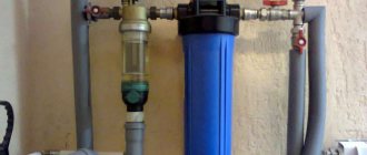
Good day, dear reader! Are you familiar with the situation when the faucet in the kitchen or bathroom breaks down and starts leaking constantly?
If it is not repaired or even replaced in time, then you can flood not only your apartment, but also your neighbors below. In order to be able to stop the water supply during repairs, a water valve must be installed at the entrance to the apartment. It is also advisable to have a separate valve-type shut-off device in front of the washing machine and each plumbing fixture, so that in the event of an emergency, only a certain area is disconnected from the water supply system, and not the entire water supply.
Device design
The valve design is quite simple, and the product consists of the following main parts:
- Frame.
- Locking device.
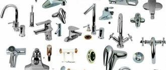
- Handwheel or locking handle.
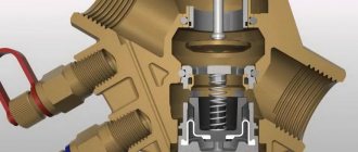
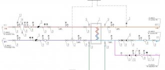
The body of the product is made by casting. A locking device is installed inside the housing, and the flywheel is brought out. The body also has threads on both sides, through which the valve is connected to a water or gas pipeline. The cross-sectional diagram of shut-off valves is as follows:
Types of shut-off valves
The following types of shut-off pipeline valves are distinguished:
- taps;
- gates (valves);
- valves;
- flaps.
Crane classification
Shut-off valves are primarily designed for low-pressure domestic pipelines.
The shut-off valve design is as follows:
- frame;
- locking element;
- handle;
- set of sealing gaskets.
Elements included in the stopcock
Devices can be classified according to several criteria:
- type of locking element;
- installation method.
An element that blocks the flow of a passing medium can be:
- ball. In accordance with this, the valve is called a ball valve (figure above);
- cone in the form of a plug (plug valve).
Plug type stopcock
The taps can be attached to the pipeline:
coupling method. The fixing nuts are screwed onto the thread prepared on the pipe;
Threaded tap
- flange method. The fixing elements are flanges connected to each other with bolts;
- welding method.
Devices mounted on flanges and by welding
Each tap has its own symbol. The markings on the device body must include:
- nominal diameter (DN);
- conditional pressure for which the device is designed (PN);
- material used to make the tap;
- manufacturer;
- additional reference materials (date of manufacture, batch number, etc.).
Symbols of the main parameters of the crane
If you know the markings, you can always choose a locking device yourself.
Using Gates
A shut-off valve (valve) consists of a body with two ends for attaching the device and a seat that is closed by a shutter.
Pipe shut-off valve
The main distinguishing feature of a valve from a faucet is its high tightness class, which allows the device to be used on gas pipelines.
A valve, like a faucet, can be connected to a pipeline using couplings, flanges or welding.
Valves are produced that are actuated by:
- flywheel (manual control);
- electric drive (electronic control), including using a remote control.
The marking of shut-off valves also contains:
- symbol of the device model;
- passage;
- designation of the type of connection to the pipeline;
- pressure;
- execution material;
- Climatic performance;
- document on the basis of which the valve is manufactured.
Designation of valve parameters
Purpose and types of valves
The most commonly used element of any pipeline is the valve. The device consists of a body and a cover, between which the shutter is located.
The simplest type of shut-off valves
The purpose of shut-off valves - valves - is any pipelines whose diameter varies from 15 mm to 2000 mm.
The advantages of the device, compared to other types of shut-off valves, are:
- ease of maintenance and design;
- small sizes;
- low resistance.
Gate valves can be made from the following materials:
- become;
- cast iron;
- non-ferrous metals and alloys made from them.
The valves are controlled:
- manually (rotating the handle);
- electric drive;
- hydraulic drive.
Valves with electric or hydraulic drive are mainly installed on industrial pipelines.
The designation of shut-off valves (valve) determines:
- type and name of the device;
- nominal working diameter;
- maximum pressure in the system;
- type of drive;
- position of the device in working condition;
- accommodation category;
- Climatic performance;
- type of connection of the device to the pipeline.
Designation of valve parameters
Purpose of dampers
The closing element in the damper is a disk that rotates around an axis.
Type of shut-off valves for pipelines
Valves are mainly used on pipelines that have a large diameter and are under low pressure, since the tightness class of the device is quite low.
The damper can be controlled:
- a flywheel that drives the axis of rotation (manual control);
- hydraulic drive;
- electric drive.
In most cases, the body of the locking device is made of cast iron, and the rotary disk is made of steel.
Dampers are installed:
- welding method;
- flange fasteners.
The valves can be used in chemical pipelines and sewer systems. They are practically not used for water supply or heating.
The brand of shut-off valves - valves, as well as the batch number, diameter, pressure and area of definition are indicated on the device body similarly to the previously given diagrams.
What types of valves are there?
The valve is a shut-off and regulating device mounted on a threaded spindle that closes the passage in the horizontal plane.
The technical conditions for its manufacture are regulated by GOST 12.2.063-81, GOST 5761-74. The water valve is available in several modifications, differing in:
- housing designs (direct-flow, pass-through, corner, mixing);
- method of sealing the joint between the cover and the movable element of the shutter (bellows, stuffing box);
- location of the running nut (submersible or external type nut thread);
- material for manufacturing the main elements (brass, cast iron, steel);
- method of fastening to the pipeline (flanged, coupling, pin-type, fitting, welded fittings);
- designs of the locking element (ball, valve, cork, wedge);
- type of force transmission to the working mechanism (manual control, electric drive).
Mounting methods
Water valves can be connected to the process in different ways: fixed using special elements or mounted by welding.
Flange connection
This type of connection uses a special metal flange with a rubber gasket.
Loose flanges are placed on the end of the pipe and the valve nozzle, a gasket is installed between them, then the entire assembly is bolted together.
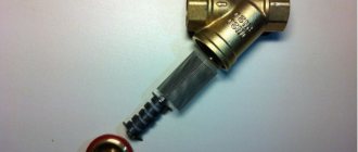
Coupling fittings
The connecting pipe has an internal thread with a fine pitch, and the outside is shaped like a hexagon for ease of use with a wrench. The coupling is screwed onto the thread and sealed with flax strands or FUM tape.
Tsapkova
This method of fastening is characterized by the presence of an external thread at the end of the connecting pipe and a collar at the end of the pipeline.
The valve branch pipe is pressed against the pipe with its end and secured in this position using a union nut. The tightness of the connection is ensured by a metal gasket and special lubricants.
Choke
The fitting is a short piece of pipe (bushing) with internal threads at both ends. With this type of connection, the connecting ends of the fittings are screwed onto the pipe and secured with a union nut.
Welding
This is a one-piece type of connection, the tightness of which is ensured by welding.
Design features of the case
Valves, depending on the shape of the body and the method of installation on the pipeline, can be:
- direct-flow - in them the flow of transported liquid moves through the body from inlet to outlet without changing direction, the spindle axis is located at an angle to the axis of the passage hole. This design helps straighten the flow and reduce hydraulic resistance, but increases the working stroke of the valve, the parameters of the construction length and the weight of the product;
- pass-through - a product with the same direction of flow of moving water at the inlet and outlet and the axes of the inlet and outlet pipes shifted parallel to each other. Passing through the valve body, the water flow is forced to make at least two turns at right angles, which leads to the formation of high hydraulic resistance and the formation of stagnation zones;
- angular - in them the flow turns by 90º only once, therefore the level of hydraulic resistance is lower. Such products have restrictions on the area of use - they are placed on the pipeline plan only on its rotating sections;
- mixing - in them the adjustment of the proportions of water occurs due to the mechanical rotation of the internal elements of the body. Designed to shut off and mix cold and hot water flows.
Selection of shut-off valve (valve)
Since shut-off valves create high resistance to flow, they are most often used on steam and water pipelines.
The choice of shut-off valve will depend on the following parameters:
- Purpose and working conditions.
- Control: manual, gear, electric
- Hydraulic characteristics: tightness class, specific flow rate and others.
- Installation conditions: weight and dimensions, type of connection to the pipeline, nominal passage diameter.
- Additional requirements, if any.
The movement of the working fluid flow relative to the shut-off valve is selected depending on the pressure:
- At low pressure – flow movement above the seat
- At high pressure - flow movement above the spool
In low-pressure valves, the working fluid flows directly above the seat. The torque when closing the valve will be higher.
In high-pressure valves, the flow of the working fluid rises above the spool, creating pressing forces that reduce the torque when closing the valve. When opened, the spool rises to a distance of 25-40% from its full bore position.
Product classification
The water valve is classified according to a number of different characteristics, which include:
- Type and design of the locking device.
- Material of manufacture.
- Features of connection with water or gas pipelines.
Based on the type and design of the locking device, valves are divided into the following types:
- Valve
- Cork or cone.
- Ball.
Let's find out the main features of each type of valve, and also determine their purpose.
Valve devices
The valve valve is also called a valve tap, since the body of the product is divided into two parts by horizontal and inclined partitions. The design of the product with an inclined partition has a hole that has a groove for the valve. This hole is called a saddle.
The valve is part of the rod, which is located at the bottom of the product. An elastic gasket is inserted into the design of the product, resting against the saddle. By means of this stop in the seat, the supply of fluid flowing through the device is blocked. At the top, the rod is equipped with a thread that connects to the threaded connection of the seat nut. Using this threaded connection, the valve is raised and lowered, thereby shutting off and regulating the pressure of the supply fluid.
Products of this type have advantages and disadvantages. The advantages include:
- Withstand high pressure.
- Adjustment of water volume and pressure.
- Easy to operate.
- If the locking device fails, it can be replaced.
The disadvantages of such a device are:
- High rate of abrasion of the gasket, since with frequent opening and closing of the device, contact of rubber with metal occurs.
- Relatively short service life.
- To completely shut off the liquid supply, you need to rotate the flywheel for a long time.
Cone type product
A cone valve is a type of valve product. The differences between the two devices lie in the design of the locking mechanism. If in the previous version the locking mechanism is presented in the form of a partition, then in this design the device has a plug in the form of a cone. When the rod rotates, the shut-off valve is lowered into the hole in the partition, thereby stopping the flow of liquid.
The advantages and disadvantages of this type of product are similar to those of a valve type valve. The cone valve has the following structure as shown below.
Ball type device
The operating principle of this type of valve is completely different from the functioning of previous options. If previous products provide shutoff of water perpendicular to the pipeline, then with a ball-type device everything is different.
The main locking device is a ball, which has a through slot proportional to the fluid flow. Shutting off the liquid supply is ensured by moving the ball with the slot to a perpendicular position. Such valves are also called gate valves.
The advantages of such products include:
- Simplicity of design, which allows the device to be used for a long time.
- Tightness of the structure. Only the shut-off ball is in contact with water, which also affects the long service life of the product.
- Shutting off and opening the liquid supply is done by turning the handle 90 degrees or half a turn. Due to the rapid shut-off of the liquid supply, such devices are also called reversible floors.
As practice shows, the quality of valve production plays a significant role in the service life. European-made water valves have a service life of up to 10 years, while cheap Chinese analogues fail after a few years.
The disadvantages of the types of valves under consideration include:
- Inability to repair a water supply ball valve. In Chinese products, the integrity of the connection between the handle and the locking ball is compromised. This causes the handle to continue to rotate and the ball to remain in place in a stuck position.
- Inability to regulate fluid flow. It is possible to regulate the flow of liquid using such a product, but in this case the manufacturers do not guarantee the long service life of the device.
Types of control valves
Based on the type of valve mechanism, the valves for monitoring pressure in the pipeline are divided into the following devices:
Seat valve
Cell valve
Spool valve
Diaphragm valve
- Saddle. The functions of the working element of the valve are performed by a plunger, which in its design can be disc-shaped, needle-shaped or rod-shaped. It moves through one or two valve saddles, reducing its flow area. Single-seat models are installed on small-diameter pipelines, while valves with two seats are in demand on large-sized pipelines.
- Cellular. When using fittings, control and regulation of pressure in the pipeline occurs due to the valve, which has the shape of a hollow cylinder with radial perforation. It moves along a cage that acts as a guide element and a passage unit. Thanks to the design nuances, cage valves are characterized by low vibration and low noise levels.
- Spool valves. Regulation of the parameters of transported substances is carried out using a spool, which rotates at a certain angle. Controlling the spool valve does not require much effort, since the transported liquid and gaseous substances offer almost no resistance when moving the valve locking mechanism. However, such fittings are not able to provide complete tightness, so they should not be installed on high-pressure lines.
- Membrane. The cross-section of the pipeline in fittings of this type is closed using a membrane made of elastic rubber or fluoroplastic. To avoid errors during regulation, diaphragm valves are equipped with special elements that provide control of the position of the rod. Among the advantages of the valves are resistance to corrosion and aggressive environments, which allows them to be used in the petrochemical industry. Diaphragm valves are available with a hydraulic or pneumatic drive, which can be built-in or remote.
Shut-off and control valves are also in demand when installing pipelines for various purposes, which, in addition to changing the flow of transported substances, make it possible to completely shut off their circulation. The functions of a locking device in the valve are performed by a plunger. When in full contact with the seat, it provides a hermetically sealed shutoff, and in partial contact, it reduces the passage opening.
Types of valves and taps
Such significant design differences between the valve and the ball valve
determine the principle of their operation. The valve is applicable not only to open/close the flow of substances moving inside the pipe, but also to regulate it. A ball valve is used to supply or shut off substrates in a pipeline.
Types of ball valves
Photos of different types of ball valves
Photos of different types of ball valves
The main difference between a valve and a faucet is that the latter are represented by product models capable of not only stopping, but also changing the direction of movement of substances:
- two-way - used to block or open the movement of substances moved to one side of the pipeline;
- three-way L-shaped - characterized by the ability to change the direction of flow of substrates and completely stop their movement in the pipe;
- T-shaped - used to separate the flow, combine or change its direction.
It should be noted that taps are also intended to open or close a flow. If it is necessary to reduce the flow force in a certain section of the pipe, select a device with the appropriate cross-section of the hole in the sphere:
- full bore - the locking mechanism does not affect the substrates flowing through it, which is ensured by matching the diameter inside the hole to the existing pipe;
- standard bore - the lumen of the shut-off ball is 20–30% narrower compared to the cross-section of the connected pipeline;
- partial bore - the narrowing value ensures a reduction in pressure by 30–60% of the original value.
Ball valves are made of brass, cast iron, steel, and stainless steel. Therefore, depending on the material of manufacture, their technical characteristics differ.
Types of valves
Photos of various types and types of valves
Photos of various types and types of valves
To understand the difference between a faucet and a valve, you need to understand the differences in the materials from which the body is made. The following types of metals are typical for valves: cast iron, steel, bronze, brass, stainless steel.
In addition to the material, the valves differ in design
:
- walk-through - installed only on flat sections of the pipe and provide smooth regulation or shutdown of the flow of substances moving in the pipe;
- direct-flow - characterized by a minimum resistance to the moving flow and are mounted in almost any plane;
- corner - have a specific shape that allows them to be installed on corner pipelines.
Basic criteria for choosing a shut-off valve
When choosing a valve at a specialized point of sale, the technician pays attention to the following parameters:
- Type of mechanism (ball, valve).
- Material of manufacture. For metal systems, brass or bronze valves are used. For polymer ones - plastic.
- Mounting method.
- Bandwidth.
When choosing a valve based on the type of mounting, you need to consider whether the valve will be installed once and for a long time, or in the future it will be dismantled and reinstalled.
What is the difference between a valve and a faucet?
The difference is not in the type of valves, as many people, even plumbers, are accustomed to thinking. Taps and valves are different, although they are often called by the same name. This difference lies in the design of the housing. If the valve is intended to be installed at the junction of two pipes in order to, if necessary, shut off the liquid supply, then the tap is located at the end of the pipeline. A tap is a kind of limit switch that serves to supply water when the need arises.
Now you need to find out what is the difference between a valve and a gate valve. Many people believe that there is no difference between a valve and a valve, however, this is not true. What a valve is and why it is needed is already known. Now let's analyze the valve to find out its main differences from the valve.
The valve performs similar tasks as the devices discussed in the material. However, the valve is not able to regulate the flow rate, so it only closes and opens the flow. The valve cannot regulate the liquid pressure due to its design features. The damper in such a device moves only up and down. The difference between a gate valve and a valve can be seen clearly in the photo below.
Types of locking mechanism
According to the type of constipation, all water valves and taps are divided into two types:
- Valve;
- Ball;
- Cork.
Below we will take a closer look at the features of all types of these devices.
Valve
Valve taps are locking mechanisms familiar to everyone. The principle of their operation is based on blocking the passage with an elastic gasket mounted on the rod. The position of the rod is adjusted by a handwheel using a worm mechanism.
So, when the handle is rotated, the rod rises, as a result of which the passage for water opens.
Among the advantages of this mechanism it is possible to highlight:
- Ability to withstand high pressure;
- Ability to manage the flow;
- Ease of Management;
- Possibility of repair.
Along with the advantages, these products also have some disadvantages:
The gasket quickly fails because it comes into contact not only with water, but also with the iron surface. Indeed, it is possible to replace it yourself. In most cases, the device kit includes an assembly drawing of the water valve, which demonstrates how to disassemble the mechanism and replace broken parts.
- To completely open or block the passage, you need to make a couple of turns with the flywheel yourself, which is not very comfortable.
- The mechanism is less durable than other types of fittings.
Due to these circumstances, recently such taps are installed quite rarely, only in those cases when it is necessary to regulate the flow.
Ball
Ball water valves have recently become the most common. They took this name due to the fact that the locking mechanism is made in the shape of a ball with a through hole. To block the flow, the ball is rotated with its hole perpendicular to the pipeline.
The plumbing ball valve has a number of advantages, such as:
- Durability due to the simplicity of the mechanism;
- Tightness when the passage is closed;
- To open the passage, you need to rotate the handle only 90 degrees;
- Affordable price;
- Possibility of use in conjunction with servos and other devices that allow you to control the mechanism remotely or install it in automatic flow shut-off systems. (See also the article How to choose a faucet: highlights.)
As for the shortcomings, there are few of them:
- The operating instructions for the device imply its use only for completely blocking or opening a passage, i.e. it cannot be used to regulate flow. Otherwise, the mechanism will quickly depressurize.
- If the mechanism fails, it cannot be repaired.
This type of fittings is used much more often in plumbing systems.
Cork
The design of a plug-type water valve resembles a valve valve, the only thing is that the flow is shut off using a conical plug, which is attached to the stem. When the rod is lowered, the plug enters the hole and closes the passage well.
It should be emphasized that in water supply systems such fittings have recently been used very rarely, since more durable ball valves are installed instead.
What are locking devices made of?
Before you find out what valves are made of, you need to divide them into two types:
- installed in internal water supply networks;
- mounted on external water and gas pipelines.
If the product is intended for internal water supply networks, then devices made of brass, bronze, stainless steel and plastic are used. If the products are used for outdoor work, then the above materials are used, as well as additionally steel and cast iron.
- Plumbing fixtures made of brass and bronze are expensive options. However, their cost is justified by their quality and durability. Such devices are light in weight, small in size, and can also be installed not only on a water supply system to supply cold water, but also hot water. Such products are also used in heating systems, since scale does not settle on their surfaces.
- Stainless steel valves. Another good option that has a long service life. They are several times cheaper than brass and bronze devices.
- Plastic products are among the cheapest, but they are in no way inferior in quality to the above models. Their disadvantage is that they can only be installed in plastic pipelines.
Stainless steel devices are not recommended for installation in hot water and heating systems. After all, exposure to hot water causes the formation of scale, which subsequently reduces the diameter of the throughput channel.
Cast iron and steel valves are popular for installation on external pipelines. For the manufacture of such products, cast iron and steel are used, which will significantly reduce the price of the device. After all, similar products made of brass and bronze will cost tens of times more.
Manufacturing technology and materials
Various materials are used to make the valve:
- Brass. The brass product is characterized by its small dimensions, light weight, corrosion resistance and long service life. It can be installed in both cold and hot water supply systems made of steel and plastic pipes. The disadvantage is the high cost of such products.
- Cast iron. Valves made of cast iron have a fairly large mass, but are reliable, capable of withstanding increased levels of pressure, and resistant to various types of deformation. They have a low price, so they are often used for the construction of water supply systems in private and apartment buildings, country houses and garages.
- Steel. For steel products, instead of a handle, a wheel is installed on the body, by turning which you can adjust the pressure level or stop the pressure of the moving medium. They are lighter than cast iron, have a simple design, are repairable, and can be used in heating systems with higher operating temperatures and pressures, as well as in networks where there is a risk of water hammer.
What types of taps/mixer valves are there?
Depending on the purpose, there are 4 main types of water taps: valve, single-lever, with a thermostat and sensor.
Valve
These mixers are considered the most common devices.
They come in two types:
- with one valve. Such faucets can supply only one type of water - cold or hot. Used primarily for installation in the kitchen or washbasin. The body of the single-valve faucet is made of copper or brass alloy. The locking mechanism - in the form of a ceramic or worm-type valve - axle box is driven by a valve;
- with two valves. Their device includes a brass body with a chrome finish, two valves that control the cartridges (faucet - axle box).
Due to the operation of the cartridges, the pressure and temperature of the water are adjusted. The spout, depending on the modification of the mixer, can be integral with the body (not rotating) or freely rotate in different directions. Two-valve mixers are designed for mixing hot and cold water;
Single lever
A single-lever faucet has only one handle (lever), with which you can adjust the intensity of cold and hot water supply. The pressure can be increased by raising the handle up.
The temperature is adjusted by turning the lever left or right; to completely shut off the water, the handle must be lowered down.
With thermostat
This is an innovative type of device. The temperature and intensity of water flow are adjusted by setting a certain indicator on a special thermostat scale.
Contactless
The design of such mixers includes special sensors, the operating principle of which is based on the reaction of infrared rays to heat and movement.
Therefore, as soon as you bring your hands close to this mixer, it immediately works. Most often they can be seen in public places: bathrooms of airports, train stations, entertainment centers, healthcare facilities, etc.
Kitchen faucets
Kitchen faucets are similar in design to those used in bathrooms. However, such products have one feature. Kitchen faucets should be taller than those mounted on bathroom sinks. Otherwise, washing dishes becomes difficult. In addition, these faucets are sometimes supplemented with a dispenser and a separate tap designed for collecting clean water.
The best option is considered to be kitchen products with a swivel design and a long spout. Thanks to these features, water can be directed to any corner of the sink. In budget kitchen faucets, the spout angle usually does not exceed 140 degrees, in expensive ones - 180 degrees. Some models have a flexible design or are equipped with a movable mechanism.
Valve kitchen faucets
Valve mixers are easy to install and repair. But due to the fact that kitchen taps are often opened with dirty hands, such products have to be constantly washed. In addition, valve mixers consume a lot of water.
Single lever kitchen faucets
Spouts can be short, long and deep. The dimensions of the former vary between 15-18 cm. Short spouts are used for installation on sinks or used as part of a bath-shower mixer.
The dimensions of long taps exceed 20 cm. Faucets with similar spouts are often installed on kitchen sinks. Longer products are used when water supply is required both in the washbasin and in the bathroom.
Faucets with flexible spouts are mounted on kitchen sinks. Externally, they do not differ from other similar products. The difference is that such mixers are complemented by a flexible hose, the length of which reaches 70 cm.
Connecting devices to pipes
Valves are divided into two types according to the installation method:
- Coupled and threaded. The main connecting element with this connection method is the thread. It can be internal and external on the valve (popularly called “mother-father”). Fittings of this type are installed in pipelines with a pressure of no more than 1.6 MPa.
- Flanged. At the end parts of the pipes there are flanges, with the help of which cast iron or steel products are connected. Installation of such devices is carried out on main and industrial pipelines in which the water pressure exceeds 10 MPa.
Plastic valves are connected to pipelines through special welding. Knowing the features of the devices in question, you can choose the best option for the appropriate installation. Recently, ball valves have become very popular because they have a long service life, despite the inability to repair them.
Purpose
Shut-off valve (valve) - serves to shut off the flow of the working medium in the pipeline moving in one direction. Direction of movement of the working medium according to the arrow on the body. The locking element moves parallel to the flow axis.
Shut-off valves are used most often on steam and water pipelines, since they create high flow resistance, higher than gate valves. During flow, the flow bends, changes its direction, narrows, and then expands to its original size. In this case, intense vortex formation occurs.
Therefore, they are used when the movement of the medium occurs only in one direction and does not cause large hydraulic resistance. Special valves are used for manual throttling of pressure (for example, a pressure reducing valve in thermal cracking units).
It should be noted that until 1982, valves in which the valve is moved using a threaded pair of spindle and running nut were called valves. Currently, valves are also called valves with a threaded spindle and a smooth stem.
Shut-off valves must comply with the requirements of GOST 5761 (regarding gland and bellows valves, steel and non-ferrous metals), TU and KD.
Nominal pressures from PN1.6 MPa (PN16) to PN25MPa (PN250) inclusive.
How to repair a valve
This applies to valve-type valves, in which the gasket most often fails. It must be replaced with a new one, and the device will continue to work without creating problems.
Attention! The valve can be repaired without removing it from the pipeline.
- To do this, you will need a gas or adjustable wrench, which must be used to unscrew the valve axle box.
- The gasket is tightened by the nut. It must be unscrewed using a wrench of the required number or pliers.
- Ready-made gaskets are sold in stores, but you can cut them from a piece of rubber with scissors to the size of the old one.
- A hole is made in the center of the new cuff for the threaded pin protruding from the valve.
- The gasket is put on the pin and tightened with a nut.
- While the valve is disassembled, it is recommended to clean its internal cavities with a knife. The same must be done with the internal planes of the crane axle box.
- A new sealing thread is wound onto the threads of the valve axle. Linen is better.
- The axle box crane is screwed into the body by hand and pressed with a gas wrench. Don't screw it in too hard to avoid stripping the thread.
Example of control valve markings
The marking of manufactured control valves is carried out in accordance with GOST R 52720-2007 and tables of figures, which provide data on designations by type of valve and its design nuances. In addition, the regulatory documentation specifies the material used for the production of the housing and sealing elements.
Example decoding for 25s947nzh:
- the first two digits indicate the type of fittings: 25 - control valve;
- the letter indicates the material of the case: c - made of carbon steel;
- if there are three digits, the first indicates the type of drive, and the next two indicate the model number: 947 - model 47 with electric drive;
- the last letters indicate the material of the seals: nzh - the sealing surfaces of the valve are overlaid with corrosion-resistant steel.
Control valve 25s947nzh
If the valves for regulating pressure and flow of the medium are manufactured without directional or insertable sealing rings, then this is reflected on its body or valve in the form of two letters - “bk”. If there is a coating on the internal surfaces of the valves, it is indicated according to the last table of figures.
is the main supplier of valves for regulating pressure and other parameters of the working environment in Russia. We offer control valves that are reasonably priced and comply with GOST requirements.
Causes of leaks and ways to eliminate them
The main causes of leaks may be the following:
- worn gasket. If water oozes out of the tap when the valve is closed, the gasket needs to be replaced. It is made of microporous rubber, which is a reliable and wear-resistant material that is resistant to deformation and corrosion. The use of the gasket as a seal ensures a high degree of tightness and ease of maintenance of the valve. A reduction in its service life can be affected by a violation of the integrity of the edge of the seat under the valve valve. In contact with a deformed edge, the gasket fails faster and does not hold water well. To replace it, first shut off the water supply to the riser, then disassemble the device and replace the gasket with a new product;
- The oil seal is malfunctioning or its packing is worn out. The fact that the seal has become unusable or its packing has dried out can be judged by the flow of water along the walls of the stem at the moment when the valve is in the open position. The method of eliminating the leak in this case depends on the design features of the valve head. When the head has a stuffing box, it is often enough to simply tighten it more tightly. If the bushing is tightened to the limit and water does not stop leaking, then the packing needs to be replaced. The work of replacing the stuffing box is carried out with the valve closed as follows:
- unscrew and remove the oil seal bushing;
- remove old layers of stuffing using an awl or a narrow screwdriver;
- lay new filler, compacting each layer of the bundle with a screwdriver;
- install the bushing in place, tightening it by at least 2 - 3 threads.
To repair a valve whose head design includes a union nut, it is not necessary to remove the oil seal sleeve. It is enough to slightly loosen the fastening of the union nut on the rod and wind the fluffy sealant bundle over the oil seal bushing. Then the nut should be returned to its original position.
I will talk about new models of faucets installed on the side of the bathtub, built into the wall and floor-mounted in the following articles. Subscribe to our channel and share useful ideas on social networks.
Loading…
How to install it yourself?
Proper installation of a water valve is important for its safe operation and longer service life. In principle, the installation itself proceeds according to the following scheme:
- The water supply system is shut off.
- Open all the taps to allow any remaining water to drain from the pipes.
- Dismantle the worn device. The choice of dismantling method depends on the type of connection of the old product:
- pin-type - use a wrench to loosen the union nut;
- coupling - by dismantling the coupling;
- flanged - loosen the bolts used to secure the mounting flanges;
- welded - a section of pipe is cut out using a welding machine.
- Clean the pipe at the installation site from residual sealant and rust;
- Install a new valve, sealing the threaded part of the fum connection with Tangit Unilok tape or thread. For a flanged valve, no sealing material is required. Unlike fittings with a collapsible type of connection, installation of a welded device will require a special apparatus for soldering pipes.
However, there are a number of nuances that should be taken into account when working:
- choosing a convenient place to install the product so that there is no interference with the movement of the lever or handle;
- The thread may need to be lengthened. If the valve is being replaced, then after dismantling the old device, you need to clean the threads of the pipe from any remaining sealing material and try to screw a new product onto it. Quite often, during operation, corrosion destroys the metal on two or three turns of the threaded part, so it is necessary to cut off the missing turns;
- The product must be installed taking into account the direction of flow of the working medium indicated on the body of this type of shut-off valve.
Scope of application
Shut-off valves are used to regulate the working flow. They are installed on systems to ensure good sealing of connections. Areas of application:
- Chemical, gas, oil industries.
- House construction, production of heating systems, water supply, gas.
With their help, you can control not only the liquid, but also the gas environment.
Application of shut-off valve
Advantages and disadvantages
Check valves have strengths and weaknesses. Advantages:
- In case of breakdowns, you can replace any part of the structure.
- Reliable pipeline shut-off, high tightness.
- The device opens slowly, and the system does not experience shocks from the working mixture, overloads, or pressure surges.
- When working with a part, you do not need to exert much effort.
- Models equipped with an electric drive allow you to set the algorithm for opening and closing the damper based on time or depending on changes in pressure.
- Complex shape of the flow part.
- High price.
- If the structure has seals, additional maintenance of the equipment is necessary.
- If the flow part has defects, stagnation occurs that can destroy the structure.
Taking into account the disadvantages, many problems can be avoided when operating locking mechanisms.
How to choose a faucet
In order for the selected model to serve you for a long time, you need to pay special attention to a number of factors when selecting shut-off valves:
- The faucet must have a sufficiently thick spout, otherwise it will begin to leak after a year of use;
- Be sure to read the manufacturer's instructions, which indicate the technical purpose of the crane. Not all touch and thermostatic models are suitable for showers, and some lever models are suitable for sinks;
- If the gaskets are made of rubber, then several times a year it will be necessary to carry out scheduled repairs - change them. Models with plastic gaskets are somewhat more expensive, but do not require frequent intervention;
- Touchless faucets have one drawback - their device requires power to the control circuit. It can be connected via wiring, an outlet or to a portable battery. Consider these features of sensor faucets in advance.
Tap for water supply
Purpose
In arbitrary water supply networks - central, local or autonomous - shut-off and control equipment is used. The most common type of equipment is a water faucet.
The device is designed to regulate the throughput capacity and pressure functions of a pipeline by transforming the cross-sectional area of the lumen of the pipe channel.
The products will be able to perform two main functions:
- Locking function. The fittings have two positions - “open” and “closed”, and help to block or unlock the pipe channel. For the most part, shut-off valves have a small and ball-shaped handle rotation angle;
- Adjustment function. Here, the closed and open positions are the extreme points, and the device allows you to smoothly change the cross-section of the lumen between these extreme positions. Such faucets are used on sinks and sinks, as well as in a channel version. They can have different designs.
Shut-off and shut-off and control valves are installed at the entrances of main pipes to the facility, in each individual room, at intersections and branches, before and after the end of metering equipment and plumbing fixtures, before and after the end of pumping equipment, at water intake points.
This widespread use is explained by the fact that plumbing equipment quite often breaks down and requires repair; in addition, preventive measures are often taken that require turning off the water supply. Using shut-off valves, it is possible to cut off a section of the network or a device from the system and replace it normally without draining the water.
varieties and device
Devices can be classified according to various parameters.
To begin with, let's divide them according to their intended purpose:
- Products for household needs. These are the familiar faucets on bathtubs and washbasins, kitchen appliances, etc.;
- For business needs. These are taps installed at the end of a pipe to connect irrigation hoses, water kits and other similar needs. They can be ball or valve;
- For the needs of the water supply system. These devices are built into the system and have a coupling design (much more often). With rare exceptions, these are ball valves.
For domestic needs, not simple designs are used, but mixing ones. They allow you to regulate not only the pressure, but also the temperature of the water by mixing warm and cold flows in various proportions.
The following possible solutions are possible:
- Two-valve. The mixer has two separate valves for warm and cold water. Adjustment is made by both thumbwheels;
- Single lever or surgical. The mixer has one handle that regulates the pressure and proportion of the mixture;
- Automatic. The mixer is a three-way valve with a thermostat, and opening is carried out by a simple ceramic axle box or a servo drive at the command of a displacement sensor. Such designs are still distinguished by too high a price.
There are four types of designs: worm, ball, ceramic valve boxes and ceramic lever cartridges for the mixer.
The former are obsolete and are actually not used, since they are the least reliable and require frequent replacement of rubber gaskets.
Ball structures are easy to construct: a spherical plug with an axial slot is installed in the coupling body, which fits well to the saddle in which it is located. A spindle is attached to the ball. Using the spindle, we can turn the plug either with the slot facing the channel lumen, or with the side without the slot.
Ceramic locking mechanisms use the same principle, only it is not the ball that moves, but one plate relative to the other. Ceramic axle boxes, like cartridges, are distinguished by high reliability, smooth running, and quiet operation. But they are sensitive to water quality and require the installation of purification filters.
In most cases, household taps are simpler in design - they do not have a mixer and are a simple valve-type locking mechanism. Modern models are equipped with a ball mechanism or a ceramic valve axle box; worm-type valves are slowly being forced out of the market.
It must be stated that ball and valve mechanisms are used not only in water supply networks: they are installed on all types of pipes, so quite often the client is not able to understand how a gas tap differs from a water tap. Their designs are monotonous, only the materials and some nuances differ.