The TIM JH-1036 pumping and mixing group has an adjustable bypass. There is a scale with a gradation from 0 to 5, but it is no longer possible to find out what these numbers mean after installing the bypass. It is difficult to understand why it is needed, because other mixing units for heated floors do not have such a device.
I had to study in great detail the operation of the bypass of the mixing unit as a result of incorrect connection of its input and output to the heating system.
After the previous installation of the TIM JH-1036 mixing unit, it was not possible to configure the bypass, since there are no instructions for setting it up, and I did not study the design before installation - do not remove it. Now, before installation, I studied and took photographs of the internal structure of the mixing unit.
What regulates the bypass of the TIM JH-1036 mixing unit.
The mixing unit has a conditional mixing chamber through which the underfloor heating circuit and the boiler heating circuit pass.
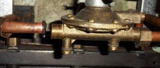
Typically, a heated floor mixing unit has one adjustment parameter - the water temperature in the heated floor circuit. The TIM JH-1036 mixing unit also has some kind of bypass, and even adjustable. And this is not the bypass balancing bypass, which is triggered by excessive pressure developed by the pump.
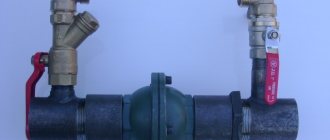
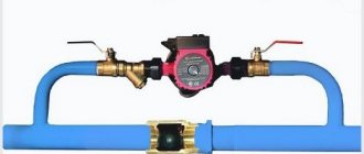
The pressure balancing bypass can be seen in the photo - the rightmost personal belongings.
I need it because it is possible to block all heating directions of the heated floor as a result of automatic regulation. By the way, I still haven’t figured out how to regulate the balancing bypass TIM M307-4 - maybe someone can tell me.
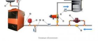
As for the mixing chamber bypass, you can find the following graphic explanation of the operation of the mixing unit bypass:
Little is clear from these diagrams.
Moreover, it is not clear what the numbers on the scale mean and what the current value is tied to. All this can be found out only by holding the TIM JH-1036 mixing unit in your hands:
It turns out that the adjusting screw turns the cylinder, which has a slot that closes when turned. Through this slot, water can be pumped by a circulation pump, bypassing the conditional mixing chamber.
It should be taken into account that the sticker with a scale from 0 to 5 can be pasted arbitrarily.
The maximum opening of the slot (pictured above) corresponds to setting the adjusting screw to position 5 (pictured below).
The technological ledge on the mixing chamber body can be taken as a conventional point for reading the scale value. When the scale value is 0, the gap is maximally closed. In this position, all the water pumped by the circulation pump along the contours of the heated floor passes through the mixing chamber.
With the bypass completely closed, the thermal power of energy taken by the mixing unit from the heating system is maximum.
If the bypass is completely open, then part of the water circulates through the heating circuits without entering the mixing chamber - and the thermal power of extraction is minimal.
But in practice it turned out that not only thermal power is regulated by the bypass.
In what cases can you do without a pump?
The movement of coolant in the circuit can occur due to the laws of physics. That is, the heated working fluid rises up, and the cooled one goes down. This is how the room is heated, this is how a heated floor works without a pump from the boiler.
Most of all, such systems are used in country houses or dachas. This is due to the fact that in suburban conditions the power supply is not always stable or does not exist at all. Therefore, it is not always advisable to use equipment with forced circulation.
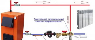
On the Internet resources of companies that install such equipment, you can find a connection diagram for a pump for a heated floor.
Water heated floor is a system with a low supply temperature (up to 45 oC). The system also has temperature restrictions for the surface itself - from 26 to 31 °C. There are many different schemes for installing such a system. But there are the best schemes - there are only 4 of them. It is worth considering each of these schemes in detail.
Experimental determination of the value set by the bypass.
Before installing the bypass, it would not hurt to make sure what value corresponds to the full opening and closing of the bypass.
Just be careful - the edges of the crack are sharp, like blades.
If the mixing unit is already installed, but the sticker with the 0-5 scale is affixed differently, you can carry out an experiment.
By turning the adjusting screw with a 10mm wrench, find out what position of the scale is the maximum and minimum water flow rate on the flow meters of the underfloor heating manifold.
If there is no collector or flow meters, which is very in vain, you can find the maximum and minimum temperatures at a limited temperature of the coolant in the main system (at the inlet to the mixing unit) and the maximum possible setting of the thermostatic head of the mixer.
The temperature of the coolant on the boiler is limited so that the mixer cannot cope with the set temperature.
Features of automatic devices
To ensure efficient operation of the thermomixing valve, the process of creating a mixed fluid flow must be continuously monitored. It is better if this is done automatically.
Automatically controlled devices are regulated by electrical or pneumatic components.
- Electric drives are relatively inexpensive and easy to connect. This largely explains their popularity and wide distribution. On the other hand, their dependence on power supply and the need for periodic maintenance make them not reliable enough.
- Pneumatic actuators are more expensive, and their connection procedure is more complicated. However, these shortcomings are compensated by a long service life and complete autonomy.
How the bypass of the TIM JH-1036 mixing unit works.
It would seem: we set the thermal power of the mixing unit to maximum, completely closing the bypass slot - and that’s it.
But the flow meters of the underfloor heating collector make it possible to find out that not only the thermal power is regulated by the bypass. When the bypass is completely closed, the floats of the flow meters float up sharply.
It turns out that the water flow through the heating circuit with a completely open bypass is more than twice as much as with a completely closed one.
This is not surprising - pumping water through the mixing chamber requires pump power, which affects the speed of water flow.
At maximum thermal power of the mixing unit, the flow rate of water along the contours of the heated floor is minimal. To uniformly heat the entire underfloor heating circuit, it may be necessary to turn on the pump at second speed, which will increase the noise of the heating system.
It turned out that in my system the minimum thermal power of the mixing unit is sufficient to ensure a coolant temperature of 32 degrees at the supply manifold with all directions of underfloor heating open, even when starting a cold heated floor.
But in other cases it may be necessary to increase the selection power.
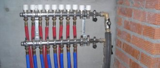
Assembling and connecting the water floor collector
A manifold for underfloor heating is a distribution unit that redirects the coolant from the heating boiler through several circuits of the floor heating system.
But depending on the configuration of the structure, it may also be assigned other functional tasks. For example, deaerating the system, adjusting the supply of coolant volumes and monitoring its flow using manual or automated flow meters. This actually ensures the maintenance of the required temperature in the heating circuits of the heated floor (HF). Among heating system installers, due to the characteristic appearance of the collector, another slang designation for it is widespread - “comb”.
How does installing a bypass mixing unit TIM JH-1036 affect the heating system.
It was necessary to carefully study the operation of the mixing unit as a result of incorrect connection of the mixing unit to the heating system.
Different positions of the bypass adjustment led to the fact that different pipes connecting the mixing unit to the heating circuit were warm.
That is, the supply and return of the mixing unit swapped places when the bypass adjustment position changed. Mystic.
So I found out that I made the connection incorrectly, having mixed up the supply and return to the mixing unit .
Theoretically, the circulation pump of the heating floor mixing unit should not have influenced the heating boiler circuit in any way - the mixing unit pump releases water at the same point from which it takes it. The circulation pump of the mixing unit pumps water along the contours of the heated floor, and the boiler circulation pump pumps water through the mixing chamber of the mixing unit.
But involuntary experiments made it possible to find out that even the minimum power of the mixing unit pump with a closed bypass is enough to carry out additional circulation in the main heating circuit.
This is possible if we assume that the equivalent circuit (by analogy with problems in electrical engineering) of a heating system with a TIM JH-1036 mixing unit is as follows:
Where “R1” and “R2” are resistances in the mixing chamber, regulated by the bypass.
“Boiler circuit” is an old heating system with radiators and a boiler.
It’s not for nothing that the mixing unit clearly indicates which pipe should be the supply pipe. The photo shows a correctly connected mixing unit.
Then I decided that it wouldn’t hurt to familiarize myself with the theoretical foundations of the operation of water-heated floors, and as a result I created a page with links to the theory.
Devices for creating a collector unit
A typical standard distribution unit includes devices for efficient operation:
- Mixing valve to set the temperature of warm water;
- Pump to increase the pressure in the system;
- Balancing and locking valves;
- Manifold for inlet and outlet;
- Thermoregulatory device with control sensor;
- Pressure gauges for determining network pressure;
- Devices for removing air bubbles from the heating system;
- Connecting elements for various pipe diameters.
Two pumping and mixing units for underfloor heating in one heating system.
I ended up with two underfloor heating mixers in one heating system.
I made one right away at the first stage of repair and installed it temporarily.
So far, this mixer has controlled one branch of the heated floor. Then he intended to move it after the renovation was completed in other rooms. I laid pipes in the floor to connect this branch to the mixer in a new location.
But nothing is more permanent than temporary.
And in a new location he installed another similar mixer.
Someday I will remove the first mixing unit - the manifold of the second mixing unit has fittings for connecting this branch and the pipes have already been laid.
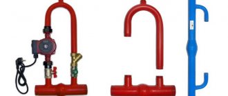
Please note that the mixer in the first photo is not capable of providing a coolant supply temperature of more than 25 degrees when the temperature set on the boiler is 50 degrees.
The photo shows a coolant temperature of 30 degrees, achieved when the boiler temperature is 60 degrees and the thermostatic mixer head is set to 40 degrees.
This is understandable with such a connection.
The paradox is that this (25 degrees) is enough to relatively quickly heat the room by a couple of degrees, maintaining the set temperature.
Choosing a durable bracelet material
The basis for such an accessory can vary significantly in shape and material. The most popular options include the following:
- cords (made of cotton, polystyrene, suede, rubber and other materials);
- rigid base (wire with memory);
- silicone (ideal for children's creativity);
- fishing line (elastic backing used in mass production of accessories);
- leather (this type of base is quite difficult to process, but jewelry created on its basis looks very noble).
Reference! Metal bases are considered the most durable, but laces and fishing line are considered the most popular.
Select the bypass adjustment value 0-5 depending on the situation.
Using the example of these two mixers, we can now show the difference between the different bypass adjustments of the TIM JH-1036 mixing unit.
Bypass setting value is 0.
The first mixer operates in conditions where the bottleneck of the system is the heat supply from the system.
It is connected like a radiator in a one-pipe system.
Just in case, I made a thickening at the connection section from 25 to 32 diameters and installed a tap, since I doubted that a sufficient amount of water would flow in and provide sufficient power.
This local heating subsystem is built, of course, on one mixing unit without a collector group.
There should be no problems with circulation along one circuit.
Therefore, we set the value of the bypass adjustment bolt to 0.
We make the circulation through the heated floor circuit minimal, and the circulation through the mixing chamber maximum.
It was shown above that here the mixer pump will help the circulation through the heating system a little more.
Bypass setting value 5.
In this case, on the contrary, the heated floor mixer is connected directly to the boiler in parallel to a single-pipe system with batteries.
There are no problems with supplying the required thermal power to the mixer.
But turning 4 heating circuits will not be as easy as one.
Therefore, we set the bypass adjustment value to 5.
We make the circulation through the heated floor circuit maximum, and the circulation through the mixing chamber minimal.
In addition, with such an installation we further limit the influence of this circulation pump on the main system.
Passport TIM TIM JH-1036 pasport-smesitelnogo-uzla-tim-jh-1036.pdf
Twin passport Profactor PF MB 841 pasport-mb_841_nasosno_smesitelnyj_uzel.pdf
- How I adapted the TIM JH-1036 mixing unit for underfloor heating. How much does it cost and where to buy equipment for a TIM warm field - Estimate
- How to set up the bypass of the TIM JH-1036 mixing unit
How to make a sliding loop?
A person, in the course of his life, uses a diverse set of various knots and loops. Some of the most popular fasteners are simple sliding devices and various variations based on them.
There are many ways and options for knitting such designs. Sliding loops are used by sailors, they are necessary for slingers, climbers, they have found their application among fishermen and hunters, and are indispensable in handicrafts, medicine, and everyday life. These are convenient and very reliable devices. There are several of the simplest ways to tie a sliding loop:
| A simple knot is made at the end of the rope, not tightened. A loop is formed. The free edge is passed through the turns of the knot. The knot is pulled up, holding the bottom of the loop. |