Any heating system, provided, of course, that it is designed, installed and debugged correctly, is a very complex “organism” in which each “organ” performs a specific important function. Often, the owners of houses or apartments do not even think about what role is assigned to this or that element of the system: everything works - and oh well...
Meanwhile, it will never be superfluous to have such information. It is rightly said that knowledge equips, and it is much easier for a person who has an idea of the purpose and importance of any of the instruments or devices of the system to operate it without leading to emergency situations. He knows exactly what performance to expect from his equipment. And, in the end, he has much less chance of becoming a “victim” for unscrupulous plumbers (and sometimes even complete crooks) who are ready, with an affected air of importance, to “cheat” unrealistic money for a completely trivial job.
Bypass in the heating system - what is it?
For example, many have probably heard the tricky name “bypass”, but have a very vague idea of what it is and what it is needed for. Meanwhile, the role of this simple element, in principle, is difficult to overestimate. Let's take a closer look at the bypass in the heating system, what it is, and what functionality is assigned to it.
Bypass device
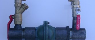
A bypass is a bypass part of the pipeline that ensures the coolant moves along a path that bypasses a certain section of the pipeline. One edge of the circuit is connected to the supply pipe, and the second to the return pipe. Various elements of the heating system, such as pumps, are usually installed on the bypass.
At the connection point between the bypass and the inlet pipe of the device that needs to be bypassed, a shut-off valve is installed. Its presence makes it possible to direct the flow of liquid parallel to the device itself and regulate the intensity of the coolant supply. A valve is also installed on the return pipe, which allows you to exclude a section of the pipeline from the system without the need to stop it.
Types of bypasses for heating
When installing a bypass, shut-off valves are installed not only on the pipes of the connected device, but also on the bypass itself. The type of fittings used allows us to classify several types of bypasses, each of which is suitable for certain operating conditions.
The following types of bypasses exist:
- Unregulated;
- With manual control;
- Automatic.
The characteristics of devices with different types of shut-off valves have significant differences, so before installing a bypass in the heating system, you need to carefully consider each type.
Unregulated bypass
The device of unregulated bypasses is a simple pipe that does not have any equipment. The pipe is constantly in an open state, and the liquid moves through it arbitrarily, that is, there is no opportunity to influence the intensity of the water flow. Unregulated bypass pipes are most often used to connect heating appliances.
When designing a heating system, it is necessary to take into account the fact that water always moves primarily through those areas where the hydraulic resistance is minimal. In the case of a bypass, this means that the internal diameter of its vertical section must be smaller than the internal cross-section of the main pipeline. If this requirement is not met, the coolant will simply gravitate towards the bypass.
When designing horizontal heating distribution, other rules apply that must be taken into account before making a bypass into the heating system. The heated coolant has a reduced specific gravity and always tries to move upward. In order for the system to operate normally taking into account this rule, the diameter of the lower part of the bypass must match the diameter of the main line, and the cross-section of the pipe leading to the radiator must be smaller.
How to choose a ball valve
If we imagine the mechanics and physics of closing a pipe with a ball valve ball, then a logical question arises: how will a ball valve work if it is installed not vertically, but horizontally or at an angle.
Practitioners recommend using a cast iron valve “Tech-Pol” (Poland). It works in both horizontal and vertical positions.
Bypasses with manual adjustment
Bypasses that are adjusted manually (manual bypasses) are equipped with ball valves. The use of ball valves is determined by the fact that they do not change the pipeline capacity at all when switching, since the hydraulic resistance in the system does not change. This quality makes the ball valve an optimal option for bypass.
Shut-off valves of this type allow you to regulate the volume of liquid that passes through the bypass section. When the tap is closed, the coolant moves in full along the main line. The operation of ball valves has one important nuance - they need to be turned regularly, even if there is no need to adjust the system. This is due to the fact that if left stagnant for a long time, the taps may become tightly stuck and will have to be replaced. Sometimes a heating system feed valve is also installed, which plays a significant role.
Manual bypasses in heating systems can be used in several ways. Most often they are used to connect batteries to a single-pipe main, as well as for piping circulation pumps.
Installation errors
Some home, or rather, apartment craftsmen, when replacing old cast-iron radiators with new aluminum ones, deliberately make two stupid mistakes:
- install a ball valve on a straight bypass pipe in order to direct all the coolant into its own battery;
- Having listened to the advice of “smart” people, they assemble a mixing unit with a three-way valve in order to regulate the heat transfer of the heating device.
Let’s immediately make a reservation that such installation in a private house is not considered a mistake: you live there alone and control the heating yourself. In a high-rise building, such actions harm your neighbors, since you unbalance the system and take away more heat. This means that adjacent apartments receive less. How this happens, watch the video:
Instead of further listing the errors, we suggest that you familiarize yourself with the recommendations on how to properly install the bypass yourself:
- The jumper on the battery of an apartment building is a pipe without any shut-off fittings or valves. The maximum that is allowed is to reduce the diameter by 1 standard size (riser DN 20 - connector DN 15);
- If you want to regulate the heat transfer of radiators, please install manual or automatic thermostats. There are special full-bore models for centralized networks.
In multi-storey buildings with common risers, it is unacceptable to install fittings on the bypass pipeline
- If energy-independent gravitational heating is installed in a country house, install the pump only on the bypass. Gravity flow is not provided - no jumper is needed.
- When assembling mixing units yourself, make sure that the circulation pump is on the side of the open outlet of the valve. Other options don't work.
- A three-way valve equipped with a thermal head operates from a remote temperature sensor. Place the latter on the pipe behind the valve, where the mixed coolant exits. Then the element can be guided by its temperature.
Point #3 requires clarification. With 3-way valves, one pipe is always open - the one from which the resulting mixture comes out. A pump is installed on the same side. If the unit is placed on any inlet pipe, then further events will follow one of two scenarios: the circulation will stop or the coolant will flow through the bypass, close in the boiler circuit and not get into the radiators.
Automatic bypasses
Bypasses with automatic adjustment are usually installed in the piping of a pump installed in a system with natural coolant circulation. Such heating systems can operate independently, but thanks to the pump, the speed of fluid movement along the circuit increases, which reduces heat losses and increases heating efficiency.
The presence of an automatic bypass in the pump piping allows the system to independently regulate its operation, i.e. no human intervention required. When the pump is running, the coolant passes through it, and the bypass is closed at this time. When the pump stops, the bypass opens and the liquid moves in it, while the stationary pump impeller cuts off the coolant flow.
Automatic bypasses are divided into two types:
- Valve;
- Injection.
The design of the first type of device contains a check ball valve. The hydraulic resistance of the valve is minimal, so the liquid easily moves on its own. When the pump is turned on, the coolant begins to move faster, is transported into the main line and diverges in two directions.
Further movement of the liquid occurs without any obstacles, and the reverse flow is blocked by the valve. The operating principle of the valve itself is extremely simple - the hydraulic pressure on the outlet side exceeds the inlet pressure, so the ball is pressed closely against the seat of the structure and does not allow the fluid to move.
Valve bypasses are quite convenient and simple, but they are very demanding on the quality of the water with which the heating system is filled. If the water contains various impurities, such as rust or scale, the valve very quickly becomes dirty and becomes unusable, as a result of which it has to be replaced.
Injection bypasses are devices similar in principle to a hydraulic elevator. A pumping unit is installed in the main line, which is connected to the main circuit using pipes of smaller diameter. With this scheme, both pipes are inserted into the main pipeline.
When the pump starts, part of the liquid enters the nozzle and is passed through the apparatus, accelerating many times in the process. The outlet pipe, which is slightly narrowed and visually resembles a nozzle, which ensures efficient pumping of liquid, also works to increase speed.
A vacuum is created behind the outlet pipe, due to which the coolant begins to be sucked out of the bypass. The flow, moving under pressure, pulls all the liquid with it, and it continues to move along the main highway with noticeable acceleration. This effect allows you to completely prevent the possibility of reverse flow of liquid.
The technology described above only works when the pump is turned on. If the pumping equipment is turned off, then the coolant in full passes through the bypass under the influence of gravitational forces.
Bypass purpose
The main function of any bypass is the ability to keep the heating system in working order even if one of its elements breaks down or there is a power outage. Devices connected via bypass can be disconnected from the system without any problems - to do this, you just need to turn off both taps, and the coolant will flow around the circuit.
Thanks to the bypass, heating can continue to operate in any case, and damaged elements can be repaired, spending any amount of time. The reliability and ease of maintenance of the heating system with a bypass increases many times over.
In autonomous heating circuits, the bypass is used to solve the following problems:
- Connecting heating devices to single-pipe wiring;
- Pumping equipment piping;
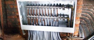
- Connecting the water heated floor distribution manifold;
- Formation of a small circulation circuit when using solid fuel heating equipment.
The bypass installation method may vary depending on its purpose in a particular heating system.
Bypass for radiator
In single-pipe heating systems, batteries are best connected using a bypass. For two-pipe circuits and manifold distributions, bypasses are not needed, since all heating devices are connected in parallel, and each of them receives coolant at the same temperature. If one of the batteries fails, it can always be removed without turning off the heating system (of course, if there are shut-off valves).
In systems with single-pipe wiring, the batteries are connected in series, so the coolant in each subsequent device cools down. The result is obvious - distant devices receive much less heat, and there can be no talk of any uniform distribution of thermal energy.
Bypasses can solve the problem. The supply and return circuits are connected by a jumper, which ensures independent flow movement. The hot coolant enters directly into the radiator, while the other part of it passes further and at the outlet is mixed with cooled water from one radiator. This scheme allows you to deliver much more heat to subsequent heating devices.
Expert answers to questions
Most often, people who are not well versed in individual heating ask the question: is a bypass needed in a two-pipe heating system near the radiators? If we consider a single-pipe heating system, a jumper is usually installed in it to ensure the operability of the entire line in the event of a shutdown or malfunction of one of the heat exchange elements in the circuit, their uniform heating, and the need for a bypass is beyond doubt. In a two-pipe distribution, such problems do not arise by definition; each circuit is connected independently of the others, and all receive coolant at the same temperature.
The simplest jumper from a piece of pipe in a heating line performs many functions in a single-pipe wiring diagram - it maintains constant temperatures on all heat exchangers and uninterrupted functioning of the entire system, and ensures high maintainability of heating elements. The bypass pipe can also be found in underfloor heating systems and piping solid fuel heating boilers, where it increases the efficiency and reliability of the equipment.
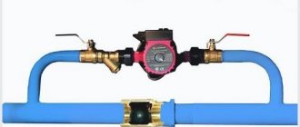
Connecting the pump via bypass
It is advisable to connect the circulation pump via bypass only in those systems that were originally designed for natural circulation, i.e. they must have an accelerating manifold, pipe slopes must be observed and their diameters must be correctly selected. The pump in such systems is not intended to ensure their operation, but to increase efficiency.
For systems that were designed for forced circulation at the design stage, a bypass is simply irrelevant. Such systems operate only due to the pump, so when it is turned off, the circulation of the coolant simply stops. Bypass in this case will not solve the problem.
When connecting the pump via a bypass line, it becomes possible for counterflow in the bypass. In addition, a closed circulation loop is formed between the pump and the bypass itself. In order for such a circuit to function normally, the bypass device must be equipped with a ball valve or check valve.
When the pump is running, the device blocks the flow of liquid through the bypass pipe. The valve does this work automatically, but the tap has to be adjusted manually. When the pump stops, the bypass opens, which allows coolants from different circuits to mix. A similar scheme is not applicable in the case of injection bypasses - they completely eliminate the possibility of reverse coolant flow.
Tips and notes
Sometimes even experts believe that the circulation pump should be installed not on the direct pipe, but on the return pipe of the heating circuit, explaining this by the fact that the water temperature in it is lower and therefore the pump will last longer.
However, this argument is not convincing, since the difference in water temperature at the inlet and outlet of the boiler rarely exceeds (and this is unacceptable!) 20 degrees Celsius. And this circulation pump, and all others similar to it, are designed for the temperature of the pumped liquid, heated to 100-110 degrees Celsius.
For heated floors
When installing a heated floor, it is imperative to install a mixing unit, in which a bypass pipeline is always built in. The bypass in this case will be used to ensure the normal operation of the heated floor, and without this element the heating will not be able to function.
It's all about the operating temperature, which must be maintained in heated floors. The coolant in the supply circuit can heat up to 80 degrees, but in a heated floor its temperature should not exceed 45 degrees. The liquid is brought to the required temperature in a mixing unit, which passes only the required volume of hot water. The entire remaining flow is directed to the bypass, where it is connected to the coolant from the return circuit, and returns to the boiler.
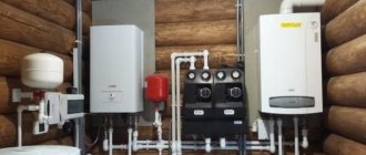
Principles for selecting pumping equipment
Having decided on the type of heating pump unit, you need to correctly calculate its optimal power. There is no point in installing a circulation pump with a large power reserve - it is more expensive and makes more noise during operation.
The circulation pump unit performs the following tasks
:
- creates a liquid pressure capable of overcoming the hydraulic resistance of the heating circuit components;
- pumps through the pipeline the volume of coolant necessary for high-quality heating of all rooms.
To correctly calculate the power of the unit, you need to know
:
- pump performance (flow rate, measured in m3/h) - the volume of coolant that is pumped by the device in one hour;
- pressure (measured in meters) is an indicator that determines the hydraulic resistance overcome by the pump.
For a cottage with several floors, with complex architecture, the calculation of the power of the pumping unit should be carried out by specialists. But for small houses, calculations are carried out using simple formulas and tables.
Determining power
Standard calculation formula: Q=0.86R/TF-TR, where
- Q – pump flow (m3/h);
- R – thermal power (kW);
- TF – coolant temperature (°C) in the supply pipe;
- TR – coolant temperature (°C) in the return at the entrance to the boiler.
It is difficult to determine the thermal power yourself, so it is more convenient to use ready-made solutions
:
Method 1. According to European standards, the thermal power indicator (R) for a small private house is 100 W/m2, for a multi-storey building - 70 W/m2, for buildings with good insulation - 30-50 W/m2. These standards are suitable for Russian regions with a mild climate.
Method 2. Russian SNiP standards are designed for climates with frosts down to -30° C. The thermal power indicator for one- and two-story houses of a small area is 173-177 W/m2, for houses with a height of 3-4 floors—97-101 W/ m2.
Method 3. The value for calculation is selected according to the table presented, based on the characteristics of the building:
There is another method for determining coolant flow (pump performance). The flow rate (Q) is equal to the boiler power (P). For example, 20 liters of coolant pass through a boiler with a power of 20 kW per minute. And each 10 kW radiator passes 10 liters of liquid per minute. To calculate the coolant flow in each heating circuit, you need to sum up the indicators of all radiators and add the indicators of the pipeline. The coolant flow in the pipeline depends on its length and diameter. The smaller the diameter, the higher the hydraulic resistance. A table compiled for a standard coolant speed of 1.5 m/sec will help you calculate the pipeline performance.
| Water consumption | Diameter in inches | Water consumption | Diameter in inches |
| 5,7 | 1/2 | 53 | 11/4 |
| 15 | 3/4 | 83 | 11/2 |
| 30 | 1 | 170320 | 221/2 |
For every 10 meters of pipeline, 0.6 m of pressure is required, which is provided by a circulation pump. For example, if the length of the heating circuit is 100 m, the pump must provide a head of 6 m.
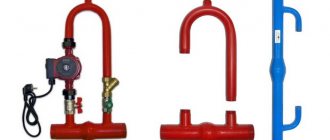
For systems with solid fuel boiler
When used in combination with solid fuel heating equipment, the bypass allows the formation of a small circulation circuit. To do this, the bypass pipe is installed in the supply, where there is a coolant heated to the limit, and is connected to a three-way valve located on the opposite side of the structure.
Thanks to the valve, hot water from the bypass and cold water coming from the return circuit are mixed. As a result, a coolant whose temperature exceeds 50 degrees is returned to the boiler for the subsequent heating cycle.
The need to return warm liquid to the boiler is determined by the fact that otherwise condensation will appear on the metal walls of the combustion chamber, which will provoke corrosion and cause damage to the unit. If you supplement the system with a bypass, then these problems can be easily avoided.
Bypass installation
Including a bypass in different types of systems has its own nuances, so before making a bypass for heating, you need to understand these points.
For example, when connecting radiators via bypass, the following rules must be observed:
- The internal cross-section of the bypass should be one step smaller than the diameter of the main pipe;
- The bypass must be installed at a minimum distance from the radiator;
- When used in apartment buildings, the bypass cannot be equipped with a tap.
Installation of a heating system bypass can be carried out both when installing a new system, and when repairing an existing structure. In the latter case, before work you need to prepare a set of pipes of suitable diameter, two tees and shut-off valves.
The inlet pipe of the structure is equipped with one of the following devices:
- Ball valve, which has minimal hydraulic resistance and completely allows coolant flow;
- A valve that allows you to manually adjust the intensity of liquid flow;
- A combination of a ball valve and an automatic thermostat - this combination can adjust the operation of the system automatically.
The outlet pipe is always equipped with a ball or shut-off valve. To connect individual elements, welding or threading can be used. Regardless of the type of connection, it must be airtight. Before putting the system into operation, you need to check it for leaks.
A bypass with a pump in the heating system is installed taking into account the following points:
- The bypass on which the pump is planned to be installed is usually part of the main line. The internal diameter of the bypass must be large enough to ensure normal natural circulation in the system. The pump is mounted on a separate pipe, the internal cross-section of which may be smaller than the diameter of the main pipeline.
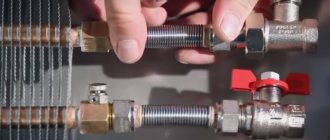
- To simplify your work, it is best to buy a pre-assembled pump unit with the necessary parameters. It is very simple to install such a structure, since all the elements are already correctly assembled and the connections are quite reliable.
- When installing it yourself, the pump must be positioned so that the impeller axis is horizontal. The surface with the terminals to which power is supplied should be directed upward - firstly, this will simplify access to the contacts, and secondly, it will eliminate the possibility of liquid getting on the contacts if the system’s seal is broken.
- The area with a bypass must be equipped with a check valve or ball valve, which prevents the flow of coolant in the opposite direction - this optimizes the operation of the system. Of course, before installing the bypass, you need to purchase all the components.
Before installing a bypass with a check valve for the circulation pump, you need to think carefully about the design of the future system and take into account all possible nuances.
Why is it needed?
A bypass is a jumper connecting the input and output of one of the elements of the heating circuit, a bypass path through which water can flow without entering the radiator, pump or even boiler.
For a circulation pump, a bypass is needed to:
- exclude the pump from the operating circuit;
- adjust the performance of the heating circuit;
- prevent idling;
- dismantle equipment at any time for repair or maintenance.
The circulation pump allows you to install a pipeline from the boiler to the radiators along arbitrary routes, increases the flow rate of the coolant, making it independent of other system parameters, thereby increasing heat transfer and efficiency. However, it also makes the heating system dependent on electricity.
If for some reason there is no electricity, you can only rely on an uninterruptible power supply unit or switch to natural circulation mode, as far as the design allows. Only the pump itself creates resistance to the coolant current when not in operation. The bypass is precisely designed to solve this problem.
For the pump, the bypass is designed as a continuation of the main pipe from the boiler to the heating circuit with a large diameter. While the pump is connected in parallel to this section. If you allow water to flow around, then there will be no resistance. To do this, a valve or ball valve is installed on the bypass.
The second point when you cannot do without a bypass is draining the coolant and refilling the system. The pump will not allow pipes and radiators to be filled freely with liquid, creating an obstacle. The result can be the formation of an air lock, which is difficult to get rid of. A completely open current through the bypass completely eliminates the problem.
The last case of fine-tuning performance is used quite rarely. It is enough to set one of two or three pump speeds to regulate the flow rate and pressure. However, if each radiator has its own thermostat, it is very important to provide protection for the pump. If all radiators are closed, and the resistance to the coolant current in the system increases, then the bypass saves from reloading the equipment, partially closing the circuit to itself.