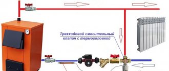
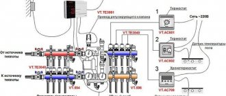
Water floor heating systems (secondary heating circuit, heated floors - TP), used together with high-temperature radiator heating (primary circuit), need to bring the coolant parameters to certain characteristics. First of all, this concerns the hydraulic and temperature coupling of both types of circuits. After all, it is important to ensure both a complete supply of coolant in the required volumes of TP communications, and to prevent overheating of the secondary low-temperature system. These tasks are assigned to the underfloor heating pumping and mixing unit (FSU). They are solved through the balanced automatic operation of shut-off and control valves and a pump unit, which ensures a dosed addition of coolant from the return line.
Picture 1
What is return in a heating system?
As mentioned earlier, all elements of the heating system are closed in a circuit, and its operation is cyclical. That is, a coolant (hot water) is supplied from the heating element to the batteries, which fills the heating devices in order to heat them and further transfer heat.
After this, the significantly cooled water returns to the boiler to heat up again and repeat the previous sequence.
Therefore, by return we mean the return of the cooled coolant back to the heating element.
What Causes Return Problems?
Of course, first of all, you should consider what reasons may cause problems with the return line.
When a cold return is detected, it is recommended to first pay attention to the water pressure inside the system. In order for the return to work as it should, the system must be designed in such a way that water continuously circulates within the circuit.
When the speed of water pushing decreases, the coolants will not be able to push cold water through in a timely manner. This in turn will cause the batteries to cool down. Rooms on the upper floors of houses are most susceptible to the problem of insufficient water pressure.
The second most common problem is a clogged system. Unfortunately, cleaning of heating pipes in multi-storey buildings is carried out much less frequently than required by the rules. Consequently, sediment settles inside the pipes, which over time clogs the circuit and causes poor water permeability, significantly reducing its speed.
It is believed that the most problematic reason is poor heating installation. That is, when an inexperienced beginner takes on the installation and laying of pipes, without the necessary knowledge, there is always a risk that he may make a mistake somewhere or select elements that do not fit together in size. That is why it is advisable to seek the services of specialists.
Options for solving the return problem
Depending on what is the root cause of the problem, appropriate methods are selected to eliminate it. For example, if the return flow does not work well due to insufficient pressure or water speed, it is recommended to purchase a special pump.
His job will be to push water into the system with a certain force to avoid stagnation and ensure continuous movement of liquid through the batteries.
Installation Features
When installing check valves in heating, you must follow several rules:
- The valve is installed in the direction of the coolant. To avoid installation problems, there is a direction arrow on the housing.
- To seal the valve, paronite gaskets are used, only taking into account that the diameter of the hole does not decrease.
- It is advisable to install a coarse mesh in front of the valve to prevent small particles from entering the mechanism and causing damage.
- The valve is installed so that other components do not interfere with its operation. This will relieve additional pressure on the valve.
Removing air lock
One of the most common and common reasons why batteries are cold is the presence of excess air in the system. This in turn prevents the continuous circulation of water in the system.
The problem can be solved quite easily by removing excess air from the system.
If there is too much air, it will not be possible to release it at once. In this case, it is recommended to open the tap every half hour or every hour. If the job is completed successfully, your radiator will be hot.
However, what can those who are faced with such a problem as the lack of a valve on the battery do? For example, old-style radiators do not have such a tap. However, even from such a situation you can find a way out. They suggest doing the following:
It is still not worth unscrewing the plug completely. You need to understand where to turn the valve. If “L” is written on the coupling, you will need to unscrew it to the right.
You don't need to use too much force to avoid damaging the pipes. When the job is done and you need to tighten the coupling back, it is recommended to wrap the threads with tow to prevent water from seeping through.
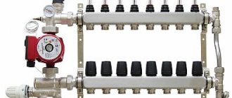
How to assemble a collector with your own hands
It is impossible to directly connect a heated floor to the boiler with your own hands. For this you need a manifold with valves. It is installed in a cabinet, and the piping begins from there. The collector is provided with access to only one person who will service the system.
The range of collectors in stores is quite large, but it is often difficult to choose the right one for your heating system. In addition, a switchgear is needed on each floor of a private house, which leads to a significant increase in costs. A homemade manifold for heated floors is the right solution, allowing you to save a significant amount of money.
Connection
Since the heating system has a supply and return branch, the collector must consist of two combs connected to them. At the joints, branches are installed to drain water and remove air from the pipes.
The collector is assembled according to the number of connected loops. At each outlet, located at the top or bottom of the comb, taps are installed to ensure that individual circuits are turned off while the rest of the heating is running. It is recommended to make the distance between them 10-20 cm.
Manifold manufacturing
Before assembling a manifold for a heated floor, you need to understand the purpose of each element. It is recommended to make combs with your own hands from a square pipe. Round threaded pipes are welded to them for connection to the boiler and to the circuits. To do this, markings are first made, then holes are drilled, and then the pipes are attached. All joints are thoroughly scalded. A plug is made at one of the ends.
The scale is knocked off, the collector is cleaned and painted with oil compounds. In Fig. Below is a simple 3 loop manifold. The comb and coolant supply pipes from the boiler are painted red, and the return pipes, through which cooled water is supplied to heating, are blue.
DIY distribution manifold
Air vents are connected to the top of the combs, and plugs are installed at the bottom to discharge sludge. Each circuit can be closed with valves, which also serve to regulate temperature and pressure.
The distribution manifold is designed to control a small system that serves as additional heating. It will be much more complex if used for the main heating system in a large house. Assembling a manifold from polypropylene pipes is much simpler, but the simplest models are made this way.
DIY collector made of polypropylene pipes
Assembly of the collector unit
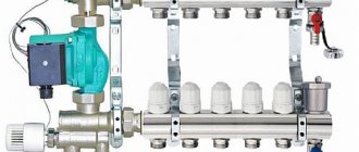
The underfloor heating manifold contains devices that ensure efficient operation of the system. Each circuit must have control valves. For a complex system, it is advisable to install automatic control valves.
Usually they operate in constant mode, the coolant flow changes only at the main supply inlet. For house areas up to 200 m², two-way valves are used. Their advantage is smooth adjustment. Valves often become clogged. Therefore, they are installed on detachable couplings (“American”) so that they can be removed for cleaning.
A more complex device is the three-way valve. It ensures mixing of forward and reverse water flows, maintaining the specified temperature at the outlet. Inside it there is a movable partition that regulates the flow of water from two inlet pipes. The device is used in all complex systems with automatic control of a large number of circuits. Its advantage is its significant throughput.
With the slightest turn of the tap, the temperature regime of the system changes. The adjustment can be manual or automatic. A three-way valve is often combined with a servo drive operating from an outdoor air temperature sensor. When the weather changes, the temperature in the rooms is maintained constant. As soon as cooling occurs, a signal from the weather sensor enters the control unit and the coolant temperature rises.
Boiler protection from cold return
Having allocated a considerable amount of funds to create a water heated floor (WF) system, the user sometimes does not receive the expected level of comfort or savings, which supporters of such heating vying with each other about. And if the calculation of communications was carried out correctly, and the installation was carried out without errors, then, most likely, the reason for the ineffectiveness of the thermal installation is in its incorrect functional settings. These primarily include adjusting the temperature of the warm water floor. At the same time, it is based on the concepts of the temperature of the coolant in the system and the surface of the floor covering, as well as the temperature regime in the rooms.
Let's look at how these concepts are linked together in practice, with different methods of TP management.
Ways to control the temperature of a heated floor
To ensure the specified requirements of sanitary and technological standards, user preferences, the heated floor can be adjusted using the following adjustment methods:
The starting points for changing system settings can be measurements of the coolant temperature in the supply or return distributors. Indeed, for water heating, unlike electric heating, it is not typical to install thermal sensors in the floor structure - they are mounted directly on the collectors. Most often, such sensors or sensitive elements are parts of thermostatic valves, through which the heated floor is adjusted.
Control signals to automatic devices can also come from air temperature sensors located in heated rooms.
What is a balancing valve
To maintain the same temperature in the batteries, they are adjusted by changing the water flow - the less coolant passes through the radiator, the lower its temperature. You can shut off the flow with any ball valve, but in this case it will not be possible to set and adjust the same temperature in the devices if there is more than one heating device. It will have to be measured with temperature sensors on the surface of the batteries and by rotating the valve to experimentally set its desired position.
Balancing valves, which are widely used for adjustment, effectively solve the problem of maintaining balance automatically or through simple calculations of the required flow rate and the corresponding settings in the devices. Structurally, the device partially blocks the flow of the coolant, reducing the cross-section of the pipes, similar to any shut-off valve, with the difference that the required supply volume is accurately set on the adjustment scales using the rotary handle of the mechanism or automatically.
How does automation work?
A thermostatic three-way valve for underfloor heating is connected in front of the manifold. A certain temperature heating mode is set on the sensor. The device starts working when the parameters are changed.
When using servo drives, a device that operates from the network is connected to the mixing valve for heated floors. The sensor heats up and closes the electrical circuit. The plate is heated, which in turn transfers heat to the thermal fluid. It expands, pressing on the rod, which makes the poppet valves work.
We recommend: How to install cable heated floors?
When using a servo drive, the heating system changes operating mode within 3 minutes. If you use a thermal head as an automatic device, it will take up to 15 minutes to heat the liquid in the thermostat.
The operating principle of a two-way valve for underfloor heating is somewhat different. When the temperature in the main increases, the thermostat causes poppet valves or a ball device to operate, which completely blocks the outlet for hot water. The cooled coolant from the return pipe returns to the floor circuit.
When the temperature decreases, the valve opens hot water and closes the return flow. There is no mixing of the liquid. The principle of operation of a two-way thermostatic valve for underfloor heating is identical to manual switching of valves, but the system operates in automatic mode.
A three-way thermostatic valve for underfloor heating is installed in a heating system for a large heating area. The equipment is necessary for a boiler that heats water to a high temperature. A two-way valve is connected to the system as additional heating control for individual rooms.
Equipment for automatic control of the heating mode can be installed in a single-circuit or double-circuit heating system. This is convenient when using various types of heating, radiator and floor. The mixer is connected before the circulation pump. I recommend installing a water filter first. When connecting, use the threaded installation method.
Operating principle of the balancing valve
The operating algorithm and principle of operation of the heating balancing valve consists in adjusting the size of the passage and, accordingly, the pressure (artificial resistance in the path of the coolant). The internal passage is subject to change through rotation of the handle and as a result of the movement of the spindle with the working cone.
When unscrewing, the spindle and working cone rise upward, which ensures maximum coolant conductivity. When twisted, the spindle presses on the seat of the differential pressure regulator and thereby blocks the path of water along the circuit.
Additional functions of the balancing valve include:
- limiting the consumption of a thermal energy source;
- pipeline closure;
- connection of measuring instruments;
- draining the working fluid.
Manual adjustment of TP collectors
The simplest, although time-consuming, setting method is to adjust the temperature of the heated floor using manual valves. The task is somewhat simplified by installing flow meters (rotameters) on the comb.
Flow meters simplify the dosage of the amount of circulating coolant (flow) in one separate circuit of the underfloor heating system. In the case of group temperature control throughout the collector, the rotameter can also be used to balance the flow of coolant (smoothing out the difference in hydraulic resistance) along loops of different lengths.
The main elements of a flow meter valve are:
Manual adjustment of the underfloor heating manifold is carried out by screwing/unscrewing manual valves or adjusting the throughput of flow meters.
Important! Improvement in the efficiency of the underfloor heating system, as a result of its manual adjustment, will be noticeable only in the case of intensive circulation of the coolant through it. This can only be achieved by using a separate heat pump.
The sequence of manually setting the temperature of a warm water floor
At the beginning of the adjustment operations, it is necessary to make sure that the pipelines of the TP system (secondary circuit) are completely filled with coolant and have no air pockets. They are filled following the main heating system (primary circuit). At this time, all shut-off and control valves on the collectors must be closed.
After opening the main valves for the supply and return of the distributors for heated floors, the shut-off devices on each of the loops are opened sequentially. Air is bled through Mayevsky valves or automatic comb air vents. It is recommended to fill the next branch only after the previous one has been completely filled and its air has been guaranteed.
Having completed filling the first loop, it is necessary to turn on the heat pump of the secondary heating circuit and circulate the coolant through its system. The efficiency of liquid circulation is checked with built-in or overhead thermometers. As a last resort, you can simply put your hands on the supply and return pipes at the same time - they should be warm, but with a slight difference in heating.
The filled first loop should be cut off from the collectors at both ends using local shut-off and control valves. Then, the above actions are carried out with the next loop.
After sequential filling of all heat pump circuits, their shut-off devices are opened and the heat pump is switched on to operating mode. The temperature of the warm water floor is adjusted through the supply of coolant to each of its branches. It is set by changing the liquid flow rate (with a valve or rotameter), and control is carried out by changing the temperature gradient between the supply and return flow. Ultimately, this difference for different circuits should be the same, within 5-150C. The longer the loop, the more intense the coolant will cool and the greater its consumption required.
Important! Heat exchange in underfloor water heating systems occurs with great inertia. The delay in heating the coating surface is especially noticeable if the pipes are laid in too thick a concrete pour (over 60-70 mm). Sometimes the effect of changing the coolant supply intensity becomes noticeable only after a few hours.
To monitor the correct adjustment of a warm water floor, it is rational to use non-contact laser or contact electric thermometers. Their installation to measure the temperature of the supply and return pipes will help reduce the time to obtain the result of changing settings from several hours to 10-15 minutes.
Why is a check valve needed?
During operation, hydraulic pressure appears inside the heating system, which may be different in different areas. The reasons for this phenomenon are very different.
Most often, this is uneven cooling of the coolant, errors in the design and assembly of the system, or its breakthrough. The result is always the same: the direction of the main fluid flow changes and it turns in the opposite direction.
This is fraught with very serious consequences, including the failure of the boiler, or even the entire system, which will require significant repair costs in the future.
For this reason, experts strongly recommend installing a check valve. The device is capable of passing liquid in only one direction. When reverse flow occurs, the locking mechanism is activated and the hole becomes impassable for the coolant.
Thus, the device is able to control the flow of liquid, passing it in only one direction.
The principle of operation of the check valve is very simple. It passes the coolant fluid in a given direction and blocks the path when it tries to move in the opposite direction
For normal operation of the system, it is necessary that the device does not create additional pressure and freely passes the coolant moving to the radiators. Therefore, it is extremely important to choose the right product.
Automatic temperature control of TP
Automatic adjustment of a heated floor can be carried out thermomechanically or electronically using electromechanical actuators that control the operation of shut-off valves.
Thermomechanical control system
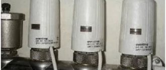
It is based on the operation of thermostatic valves or taps with thermal heads that respond to changes in coolant temperature. Various models of such shut-off and control valves are offered today by many manufacturers, for example, Oventrop. However, regardless of the name and type of thermosetting substance used in them (liquid or gas), these are thermomechanical self-regulating mechanisms that are most appropriately installed to control the temperature of one, individual circuit.
The operating principle of thermal valves is simple, which makes them very reliable and fault-tolerant. A copper, brass or bronze core installed in the device body, heated by the passing coolant flow, transfers the temperature to the thermosetting filler. In turn, the thermosetting element, which increases in volume, pushes the core, which, by moving the valve, gradually blocks the circulation of the heated liquid.
The thermostatic valve for heated floors, in addition to being installed on the distribution comb, can be mounted in a separate “unibox” type assembly. Such assemblies also include automatic air vents, which, together with thermostats, are placed in compact boxes (boxes). The use of a “unibox” allows you to adjust the temperature in a separate branch of the TP without being tied to bulky manifold cabinets, which is especially convenient with a small number of circuits.
In addition, thermomechanical floor heating controllers can have remote air sensitive elements. They allow you to configure them to control the flow of coolant not according to its temperature, but according to the air temperature in the rooms. The principle of their operation is the same, only the thermosetting substance is much more sensitive. It is advisable to install an air thermal head for simultaneous control of several circuits in one room, where water underfloor heating is the only source of heating.
Electronic control system
It consists of electronic thermometers, a controller and electric drives (actuators, servos). Electric drive mechanisms can be attached to the mixing heads of conventional control valves (valves) or be part of their design. The change in coolant supply intensity is carried out in accordance with specified threshold values. The measuring medium for the temperature sensors of the automatic floor heating temperature controller can be both the coolant and the air in the premises.
Important! Such control equipment is quite expensive, but at the same time it is capable of providing optimal operating conditions for underfloor heating and maximum energy savings. In addition, electronic regulators allow programming of the TP with binding of its operating modes to different time periods, which guarantees the user maximum thermal comfort.
Design and principle of operation
To understand what the thermo-mixing three-way valve of the most common saddle type consists of and how it works, you should study the diagram below. Inside the brass body with three nozzles, 3 chambers are arranged using the casting method, the passages between which are blocked by poppet valves. They are fixed on one axis - a rod coming out of the body on the fourth side.
In a 3-way mixing tap, the outlet pipe (from where the mixed water comes) is always open, the remaining 2 fittings are alternately closed with a thermal head
The operating principle is as follows: when you press the rod, the passage for one flow will begin to open and gradually close for another, resulting in water of the required temperature in the mixing chamber of the valve. It leaves the brass body of the element through the third pipe. The force of pressing on the rod is adjusted by a thermal head with an external temperature sensor installed in accordance with.
The whole process is worth explaining in more detail:
- Imagine that an insufficiently heated coolant comes from the hot water side. Then the mechanism passes it further, and the third pipe is closed. The remote sensor is filled with a heat-sensitive liquid and is connected through a capillary tube to a reservoir (bellows) inside the thermal head.
- When the sensor heats up, this liquid expands, its volume in the tube and bellows increases, as a result of which the latter begins to press on the three-way valve rod. The moment of pressing is determined by the adjustment on the scale of the thermostatic head, set to the required temperature.
- After this, cold water from the third pipe is mixed into the flow of heated water and the temperature of the water at the outlet of the thermal valve remains unchanged, although heating of the coolant at the inlet continues.
- If the incoming water continues to heat up above normal, then to maintain the set outlet temperature, the thermostatic valve can completely close the inlet and open the side flow. In this case, the rod lowers to its lowest position.
- As soon as the sensor detects cooling of the coolant, the head slightly releases the stem, the valve seat on the hot side opens and the addition of heated water begins.
If we are talking about a dividing valve, the principle of its operation is almost the same, only when you press the rod, one flow begins to divide into two. But in the switching element, the direction of movement is changed by the electric drive, which is described in detail in the video:
Watch this video on YouTube
The influence of the coolant supply method on the choice of control technology
Control of heating of water heated floors equipped with their own heat pumps occurs under conditions of continuous supply of coolant at high speed and in large volumes. Such systems use the admixture of cooled liquid to the supply stream to bring its energy parameters to the specified ones. The mixing is carried out in pumping and mixing units (PMU), which lower the temperature of the coolant from the primary high-temperature heating circuit to the design ones. Further adjustment of the temperature of the heated floor is carried out on the combs and has already been described above. NSU blocks provide optimal operating conditions for underfloor heating, and also allow it to be installed in unlimited areas.
However, with a small TP quadrature it is possible to avoid the use of expensive mixing units. The temperature of the coolant for the heated floor, in this case, is maintained by the method of limiting flows or by the RTL scheme. The functional principle of the circuit is the portion supply of coolant into the circuits. In each branch, the active element of the thermostatic valve, installed on the return line, having warmed up to the set temperature maximum, blocks the flow of working fluid. The heat gradually released by the coolant is dissipated in the concrete screed. After the system has cooled to the minimum temperature threshold, the valve opens and the batch feed cycle is repeated.
The simplicity of RTL control of underfloor heating makes it especially attractive. After all, it is enough to use a set of thermomechanical valves installed on the comb, or compact “unibox” type assemblies. However, when choosing an RTL scheme, you should not forget about its limitations:
Important! The use of pipes of different diameters in one system (on one collector) of underfloor heating with RTL control is strongly not recommended.
Comb selection
When choosing a comb, you need to know the need for its functionality and performance; it must have a reserve so that it can withstand sudden changes in pressure.
In addition, you need to consider:
- Material: Available in brass, plastic and stainless steel. The budget comb is made of plastic, but it is not durable. A welded stainless steel product is durable, but susceptible to corrosion. Brass manifolds are the highest quality and most reliable, but they are expensive.
- The number of valves for connecting the floor circuits - it is better to install a comb with a number of outlets equal to the floor branches. If there are more taps, then the extra ones will have to be plugged.
- Level of automation - There is now equipment that connects to thermostats and programmable controllers. They simplify the process of adjusting and monitoring temperature and coolant flow.
When purchasing a distribution unit, it is better to take a product from a well-known company, even if its price is higher - it will pay for itself during operation. Availability of appropriate warranty documentation for the product is mandatory.
Reason 6. Weak pump
It is also possible that the heated floor does not heat due to an incorrectly selected pump. Such a pump cannot properly “push” the circuits and therefore your underfloor heating does not heat up.
Dear, I have a question about heating a private house connected to central heating.
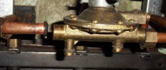
Prehistory. A house for 4 owners, there are two pipes for each half from the central riser. The direct and return pipes are 34″ in size. The pipes go into the house to the collectors. Input manifold with 4 taps, + direct output to the neighbor. From 2 taps there is a distribution for heating, from 2 taps to heated floors, one floor to the bathtub, the second heated floor in the hallway.
Return from all pipes to the collector without taps. The photo shows the collector below behind the cold water pipe.
The pipes in our quarter of the house were replaced with 20″ metal-plastic, a 16″ heated floor was laid in the bathroom and hallway, pipes were laid to the heated floor and radiators through a manifold.
The problem is that water does not circulate in the system, because, as I understand it, there is pressure both in the inlet pipe and in the return pipe. And the resistance of the general system does not provide the necessary pressure to push through the return.
One of the ways to warm up was to connect the faucet to the treatment and drain the water into the sewer until the pipes warmed up.
Tell me, would it help to install a circulation pump in the return line, or something similar to a check valve? Thank you!
UPD. I added the connection diagram, if you can call this art that way =)
Source
Despite the fact that built-in heating systems and, in particular, water heated floors are considered the most reliable, durable, and efficient, sooner or later you may encounter problems.
Having studied them in advance, it is easier to determine why the water heated floor does not work and take measures to eliminate the malfunction.
How to make a device yourself
Making a distribution unit yourself is not too troublesome and not at all expensive, so this option is increasingly being chosen by home craftsmen who want to save money on purchasing such an expensive device.
Drawing up a drawing
Before you begin assembling the comb with your own hands, you need to draw up a competent drawing or diagram of such a device, taking into account the number of circuits, load and other basic parameters.
A pre-compiled assembly diagram for the distribution unit allows all work to be done correctly, with the highest quality and speed.
Selection of the required material
To make a comb with your own hands, you will need to purchase a few of the simplest parts presented:
- ½ inch brass tee - four pieces;
- ball valve with a ½-inch threaded connection - five pieces;
- silicone sealant;
- standard ½" plug.
The purchased tees must have a configuration in which there is an internal thread on one side of the product, and an external thread on the opposite side.
Manufacturing
The sequence of self-manufacturing of a distribution comb for a “warm floor” heating system:
- Assemble the tees into a single line. To connect each subsequent tee to the previous one, external and internal threads are used, which allows you to get a straight pipe with side branches. Reliable sealing of all connections involves treating the threaded connections with silicone sealants applied to the external threads. All excess sealant must be removed using a rag.
- A standard tap is installed on the inlet part of the resulting straight pipe using silicone sealant and a threaded connection.
- A plug is installed on the opposite side of the base on a homemade comb.
- All side branches are provided with screw-in and sealable taps.
The homemade distribution comb obtained in this way is perfect for arranging a four-circuit “warm floor” system.
An equally popular option is to independently solder the comb using conventional polypropylene pipes and additional fittings. The number of tees is selected individually, and the sections of PPR pipes must have a diameter similar to them. With this option, cut pipes serve as connecting nipples for joining tees.
Video: homemade collector
https://youtube.com/watch?v=jm7lnGZZdkw
Heating a room using a modern and highly efficient “warm floor” system is one of the most practical options in terms of saving energy resources and uniform distribution of thermal energy. When installing this type of heating over a large area, it is mandatory to use a special comb with manual or automatic control.
The use of automation in the comb control system is an ideal option that allows you to obtain the maximum level of economic benefits when consuming thermal energy. However, such a device belongs to the category of non-public and inertial, so warming up and cooling of the underfloor heating system will take some time.
Possible problems and their manifestations
A malfunction in the water heated floor system manifests itself in a sharp decrease in the level of comfort in the room.
It is felt physically:
The question arises, why does a water heated floor heat poorly or is there no heating at all?
Often, such problems can arise immediately after installation of the system during the first start-up. That is why it is important to know the requirements for putting a heated water floor into operation, as well as to be able to correctly adjust the system.
In order not to worry, wondering how long it takes for a water heated floor to warm up, you should adhere to all the requirements of the installation technology when constructing a “warm pie”. One of the possible reasons for the low quality of heat transfer from the system is poor-quality thermal insulation.
Periodic recording of energy consumption and temperature can be invaluable in identifying the problem. By checking them, it is much easier to identify the malfunction in time.
The boiler does not warm up completely
The reasons why the water floor is not fully heated by the boiler may be insufficient boiler power or an incorrectly selected pump.
Often, a problem with heating a water heated floor occurs immediately after installation and first start-up. To protect yourself from the risk of encountering such a situation, you must follow the requirements for putting the heating system into operation and be able to regulate it. It is recommended to periodically record how much energy is consumed and what temperature the heating system maintains.
Why the water heated floor does not heat: faults and their elimination
Water heating built into the floor is a rather complex system of interconnected components. If the water heated floor does not work, the reasons may be different.
First of all, you need to know the basic elements of this type of heating:
It is worth taking into account possible flaws in installation. Eliminating such a malfunction as, for example, an insufficient amount of insulation and high heat loss, will be problematic, because you will have to lift the floor covering of the warm water floor, dismantle the screed and pipes.
Also, if a warm water floor does not heat, the reasons may lie in incorrect calculations during the design and, as a result, incorrectly selected system components according to the parameters. It often happens that there is not enough energy . In this case, the problem is low network voltage or insufficient boiler power.
However, we will consider the most typical breakdowns, places and causes of their occurrence, as well as ways to solve the problem.
Pipeline damage
A breakthrough of a water heated floor manifests itself in a leak and often a sharp drop in pressure in the pipes. A leak not only reduces the amount of coolant in the system, but is also fraught with destruction of the floor, flooding of neighbors and damage to property.
If a warm water floor begins to heat poorly and a leak is suspected, then the first step is to inspect the surface and joints of the floor covering. There may be no wet spots. Then you should use a thermal imager.
After determining the location of the leak, you need to carefully dismantle the floor covering and screed locally. The method of eliminating a leak comes down to excision of the damaged section of the pipe and replacing it with a new, intact one. The technology depends on the type of pipes used.
Before dismantling the coating and cutting out the pipe, you must first shut off the coolant supply to the circuit (at the collector), and then completely drain the water from the circuit. After repair, the circuit starts up. It is mandatory to check the solder or connection for leaks.
Before heating a water heated floor, it is necessary to de-air it.
Uneven heating
In cases where a water heated floor does not heat well, the reasons may lie in the uneven distribution of the coolant in the circuits. This is due to the fact that the contours, as a rule, have different lengths. If the rate of water supply at the collector to each loop is the same, then the coolant will take longer to pass through a longer circuit. Accordingly, in such loops the water cools faster.
In this case, solving the question of why the warm water floor does not warm up will be possible by adjusting the supply of coolant on the manifold to each circuit. It is necessary to check and adjust the levels of the electric drives of the supply valves.
In this case, you will have to be patient, because the time it takes for a water-heated floor to warm up depends on many factors (the design and thickness of the “warm cake”, the temperature and intensity of the water supply, the temperature outside the windows, the flooring material, what power the heater is chosen for the warm floor). water floor, etc.).
Automation tools will help to facilitate control and adjustment, namely temperature sensors and servos on the collector valves connected to an external thermostat - an analyzer that sends commands to the collector to regulate the water supply to the loops.
Electrical faults
Why doesn't a warm water floor heat up if there is no leak? Considering that some elements of the system require power from the mains to function, it can be assumed that the cause of the trouble lies precisely in them.
A common failure is the failure of the circulation pump and thermostat located in the mixing unit of the manifold. It is necessary to check whether voltage is supplied to them. This can be done with a multimeter or an indicator screwdriver. In principle, the inoperability of the pump can be determined by the absence of any noise.
After a general check of the thermostat, if the problem is not identified, it is necessary to check the resistance of each of its terminals. It is possible that the temperature sensors have failed. Therefore, it is recommended to regularly check their performance.
If you have not been able to find out on your own why the water heated floor is not heating, and nothing else has raised suspicions, it is better to seek help from a specialist.
Why do you need a bypass valve in a heated floor?
The heating system often includes control mechanisms and mechanisms that ensure safe operation. They are otherwise called heating system valves. With the help of these adjustment elements, the heat supply parameters change; they also ensure stable operation and perform automatic adjustment. Let's look at the valves and regulators of the heating system, since their purposes and functions differ.
Typically, boiler automation cannot meet the need for water at different temperatures for several circuits of the heating system. A three-way thermostatic mixing valve of the heating system comes to the rescue, which maintains the necessary thermal parameters of the coolant in the circuits of the heating system, as well as in the small circuit of the system. The valve looks like a simple tee, the metal is bronze or brass. An adjusting washer is installed at the top of this tee, under which there is material sensitive to temperature changes. And if necessary, it presses on the working rod coming out of the housing. The main task of the valve is based on maintaining the temperature of the coolant at the outlet within specified limits by adding cold or hot water . During unsuitable temperature changes, the external valve actuator presses on the stem. Next, the cone leaves the saddle and a passage opens between all channels. During operation, the three-way valve is controlled according to temperature by an external actuator.
A complex heating system contains a fairly large number of auxiliary elements, the task of which is to ensure reliability and uninterrupted operation. One of these elements is the heating system check valve. A check valve is installed to prevent flow in the opposite direction . Its elements have very high hydraulic resistance. Due to this circumstance, there are restrictions on the use of check valves in a heating system with natural circulation. There is too little pressure in such a system. At minimum pressure, it is necessary to install gravity valves with a butterfly valve; some of them can operate at a pressure of 0.001 bar. The main part of the check valve is the spring, used in almost all models. It is the spring that closes the shutter when normal parameters change. This is the principle of operation of a check valve.
It is necessary to take into account the operating parameters in a particular heating system. Therefore, select a heating system valve that has the required spring elasticity. Shut-off valves used in heating systems are usually made of the following materials: steel; brass; stainless steel; gray cast iron. Check valves are divided into the following types: disc valves; petal; ball; bivalve. These types of valves are distinguished by a locking device.
Regulating and shut-off and control heating valves systematically change the flow of coolant, from maximum to minimum , with the valve open and closed. Shut-off or shut-off valves control the coolant discretely when the valve is in the fully open or fully closed position. A control valve consists of three main blocks: the body, the throttle assembly, and the valve actuator. The closing and regulating element of the valve is the throttle assembly. When choosing a sleeve, seat, or plunger, you should pay attention to the operating conditions of the valve. The medium and its temperature, the presence of impurities, and throughput are taken into account. The main and important importance in the operation of the valve is the correct direction of supply of the working medium. It is usually marked with an arrow on the working surface of the case.
In modern realities, a thermostatic valve is a prerequisite for modern and reliable equipment in a heating system. The valve temperature is automatically adjusted. The operation of a heating system mixing valve for radiators is to limit the supply level to an individual heating radiator. The valve stem makes movements to open and close the hole. Through this hole, coolant enters the radiator. When the valve with a thermostatic head heats up, the inlet opening is closed, as a result of which the coolant flow rate decreases. The thermostatic valve constantly changes its position. And an important factor is the quality of the materials on which this product is made. The product may fail due to sticking of the rod, as well as significant corrosion and breakthrough of sealing materials. But even if the thermostatic valve fails, you can extend its service life by replacing the thermostatic element.
Heating system valves with thermal heads differ depending on the shape and type of supply to the heating system. They can be angular when connected to radiators from the floor, or they can be straight, which connect the pipes to the battery relative to the wall surface. Axial, mainly when connecting pipes from the wall to the battery. When connecting batteries sideways, a special kit is required. It uses thermostatic heads and valves. Batteries that come with a bottom connection are obviously equipped with valve-type inserts.
The operation of the batteries and the pump is disrupted due to high or low pressure levels. Correct control of the heating system will help to avoid this negative factor. The pressure in the system plays a significant role, it ensures that water gets into the pipes and radiators. Heat loss will be reduced if the pressure is standard and maintained. This is where water pressure regulators come to the rescue. Their mission is primarily to protect the system from too much pressure . The operating principle of this device is based on the fact that the heating system valve located in the regulator works as a force equalizer. Depending on the type of pressure, regulators are classified into: statistical, dynamic. It is necessary to select a pressure regulator based on throughput. This is the ability to pass the required volume of coolant, in the presence of the required constant pressure drop.
To relieve the working medium, use the bypass valve of the heating system thermostat, which operates in the return direction when the pressure increases significantly . As a rule, the pressure increases due to the achievement of the maximum temperature set manually, the supply of coolant to the radiator decreases, as a result of which the pressure increases. Heating system bypass valves are basically designed to ensure a stable difference between the return and supply pipes. When the heat load decreases, the thermostatic valves close, resulting in a pressure difference between the pipelines. As a result of using a bypass valve, the load on the pump is reduced, the return temperature increases, and the boiler is protected from corrosion. The scope of application of the heating system bypass valve is quite wide; it is also used to prevent noise generation of thermostats. Bypass valves are installed not only on an unregulated pump, but also on riser jumpers.
Any boiler equipment is a source of danger. Boilers are considered explosive because they have a water jacket, i.e. pressure vessel. One of the most reliable and widespread safety devices that reduces the danger to a minimum is the safety valve of the heating system. The installation of this device is due to the protection of heating systems from excess pressure . Often this pressure occurs as a result of boiling water in the boiler. The safety valve is installed on the supply pipe, as close to the boiler as possible. The valve has a fairly simple design. The body is made of good quality brass. The main working element of the valve is the spring. The spring, in turn, acts on the membrane, which closes the passage to the outside. The membrane is made of polymer materials, the spring is made of steel. When choosing a safety valve, it should be taken into account that full opening occurs when the pressure in the heating system increases above the value by 10%, and full closure occurs when the pressure drops below the response value by 20%. Due to these characteristics, it is necessary to select a valve with a response pressure higher than 20-30% of the actual one.
The balancing valve of the heating system is intended to regulate the coolant passing through . Liquid consumption depends on pressure. The higher the pressure, the more fluid is consumed. This device is installed on risers. A balanced system ensures continuous operation. The manual valve is used as a diaphragm, and the automatic valve maintains pressure and consumption in the risers. A manual balancing valve can shut off the system. The design is a valve type device. Manual valves can be installed in conjunction with shut-off valves.
Having installed energy metering devices, the question naturally arises of how you can regulate and control the supply of coolant, limit or add its flow. For this purpose, there are all kinds of automatic regulators, the use of which allows you to save money; they operate from outside air temperature sensors and return pipeline sensors. Another advantage of temperature controllers is that they control the temperature directly at the radiator installation site, unlike other devices. This advantage gives priority in obtaining a uniform temperature background for a comfortable stay in the room. The regulator will prevent overheating of the air in the room, which sensors on centralized automation cannot always track. It is possible to adjust the temperature for each room separately. Sometimes, when solving the adjustment issue, ordinary taps are installed. Of course, this solution reduces financial costs, but deprives a number of useful advantages. The faucet has limited functionality to open and close. There is a danger of stopping or airing the riser. By adjusting the heating using taps it is impossible to achieve the required temperature. Using automatic regulators, you can adjust the system accurately and efficiently.
Today, among heating systems used in everyday life, warm water floors are gaining popularity. The increased attention from consumers to this heating method is explained by the high efficiency of heated floors, especially when emphasis is placed on the quality of interior decoration of residential premises. Heating radiators do not always look aesthetically pleasing, while a water circuit hidden in the floor is completely invisible.
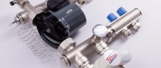
In this case, the installation of heating equipment is also captivating. With proper planning and compliance with all the necessary technological details, making heated floors in your own home is quite realistic and within the power of everyone. In order to achieve success, it is enough to have an idea of how heated floors work, which is included in the equipment package. In the process of work, you will have to deal not only with the choice of heating method for the coolant, the selection and installation of water circuit pipes and screed equipment. The key element of the “warm water floor” heating system is the heated floor mixing unit.
What kind of equipment is this? What is its design and purpose? Let's look at these issues in more detail.
Warm floors today can be found in almost any residential premises. City apartments, if the design features of the residential property allow, are often heated in this way. In many private houses and cottages, water floors are a common phenomenon. Due to its design features, the underfloor heating system can be used both as a full-fledged, main heating of residential premises, and as an auxiliary heating option. Proper installation and the availability of appropriate equipment will allow you to use water floors with maximum efficiency. And a mixing unit for your heated floors will help you with this.
Warm water floors are a low-temperature heating system. Unlike radiators, for normal operation of heating water circuits it is necessary to have a coolant whose temperature varies between 35-55 0 C. The water that circulates in the central heating system is much hotter, not to mention the coolant heated as a result of the operation of the heating boiler. The mixing unit performs the work of preparing water for water circuits. On top of that, through the collector inlet system, the coolant is distributed through the underfloor heating pipeline.
Note: it should be said that a mixing unit or mixing unit is necessary when you have expressed a desire to heat your home using heated floors. For other heating options, such equipment is not required.
Like all other heating systems that use a liquid coolant, heating using water heated floors works according to a similar scheme:
- heating source (autonomous boiler or central heating riser);
- supply and return pipelines, water circuits laid in the floor of the heated room;
- devices and instruments of the regulatory group.
Water is heated by the operation of the boiler or supplied to the system from the DHW main and central heating. In an autonomous boiler, the water is heated to a temperature of 75-95 0 C, in a central heating system the water temperature is slightly lower, 55-75 0 C. In accordance with sanitary standards, the ideal floor heating temperature should be 31 0 C, thanks to which a comfortable zone is created in the heated room stay. In order to achieve such temperature parameters, water heated to a temperature of 35-55 0 C is supplied to the loops of the water floor. The layer cake absorbs excess thermal energy, producing optimal temperature indicators on the floor surface.
In order to direct a flow of water at the required temperature into the water circuit, a mixing unit for the heated floor is installed. Otherwise, the underfloor heating system will be a waste of money. Without adjusting the temperature of the coolant, your floor will turn into a hot frying pan, and the concrete screed and floor covering will soon become unusable.
Important! It should be remembered that the mixing unit can only work if ordinary water circulates in the heating system.
The unit is mounted in close proximity to the heated room, where the loops of the heating circuit come to the surface. The equipment is connected to both pipes, to the hot water supply pipeline and to the return flow line. As a result of its work, the excessively hot coolant mixes with the cooled waste water, ultimately giving the optimal water temperature for the heating pipes.
Important! If the water in the system is not so critical for heated floors, it is not necessary to install a mixing unit. If an autonomous boiler operates for heating and supplies hot water for domestic purposes, you cannot do without a mixing unit.
It would be appropriate to say. The mixing unit and the manifold should not be confused. The first is a set of equipment, each of which individually performs its assigned functions. The collector is an integral part of the mixing unit and is designed to collect and distribute water flows in the heating system.
Based on the configuration, the operating principle of the mixing unit also follows.
The coolant from the heating source flows to the collector. The presence of a safety valve and thermostat does not allow hot water to move freely. When the water temperature is high, the automatic mode is activated. The inlet valve opens and cold water is added to the hot fluid flow, flowing in the opposite direction. When the water reaches the required temperature values, the valve closes automatically, stopping the supply of hot water to the system. This process occurs continuously and uninterruptedly during operation of the heating system.
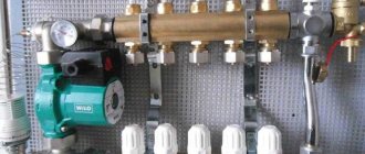
The operating principle of the equipment is simple and clear. Another thing is what devices and equipment ensure the functionality of the entire unit. The simplest option that you can make with your own hands is a mixer equipped with a manifold, safety valve and circulation pump.
The first one performs the task of distributing the flow through the water pipes of the heated floor. The safety valve ensures the supply of hot water to the collector and control of the water heating temperature.
The circulation pump imparts the required speed to the water flow, ensuring the intensity and uniformity of water supply to the underfloor heating system.
A more complex mixer design consists of a whole set of additional elements. In addition to the devices already mentioned, a manifold, a safety valve and a feed pump, the set of a conventional mixing unit includes:
- Bypass is an element that protects your equipment from overload and overheating;
- Drain, release valve;
- Shut-off valve;
- Air vents;
- Thermal relay.
The mixing unit should be a compact structure that can be successfully hidden in a manifold cabinet.
Note: if you plan to install heated floors in several rooms, each of them will require its own separate mixing unit. You can install one single block for all heating circuits, only in this case it is better to use a manifold with a large number of inputs and an additional number of safety valves.
Three-way and two-way valves are usually used to equip mixers. The second one is also called the supply valve. Thanks to its filling, a thermostat and a sensor, the valve reacts to the slightest change in the heating temperature of the water in the system, opening or closing the water supply.
For heated rooms with an area of more than 200 m2, the use of a two-way valve is not recommended.
The three-way valve has several functions. Due to its design, the valve is capable of draining and mixing. Thanks to this device, hot water coming from the heating device is mixed with the return in the mixing unit. Typically, valves with servo drives are installed on the mixture, which independently, automatically regulate the level of the mixture. By adding a three-way valve to the mixing unit, complete with a weather-compensating controller, you will receive a fully automated heating temperature control system. In addition, the three-way valve is designed to work with large area warm floors.
If you want to save money on equipment, use manual control valves. By saving on automation, you will get extra hassle for yourself. With manual adjustment, it is quite difficult to determine the optimal coolant flow in the system. Automation solves these issues easier and faster.
With the correct selection of components and compliance with all necessary technical conditions, installing the mixer should not cause difficulties. Having determined the location of the mixing unit and modeled the design of the manifold cabinet, begin assembly.
For the future. The heated floor control unit must be freely accessible. Otherwise, you will have to face difficulties during operation.
First, the pipelines coming from the heating device are connected. Next the collector is installed. Finally, the system can be equipped with sensors for adjusting pressure, pressure and thermometers. It is important to determine how the collector combs are positioned. The way you connect the distribution combs depends on what heating source your system is connected to. This can be an end connection or a regular one, top and bottom.
For the hot water supply line, it is better to use metal-plastic pipes or polymer materials. These components are able to cope with pressure surges in the system and can withstand high temperatures perfectly.
Connecting equipment to water circuits is carried out in a clear sequence using fittings. Pipes through which cooled water flows in the opposite direction are connected to the blue inlet pipes. A water loop is connected to the red pipes, providing floor heating in a heated room.
If you are planning to make a heated floor to heat large areas, you will definitely need a circulation pump. The large length of the water circuit, a large number of bends and the small diameter of the heating pipe lead to the fact that the coolant circulation in the system is noticeably weakened. By installing a circulation pump, you will ensure a normal supply of prepared water to the heating circuits. It is recommended to install the pump at the beginning of the mixing unit, where the supply pipe fits and the return pipe is connected.
The pump is installed in a strictly horizontal position. It is recommended to install pumps with several speed settings. Such models allow you to manually determine the required feed speed and flow intensity.
Having become familiar with the importance of the mixing unit for the heating system “warm water floors” and how its work works, we can say a few words about setting up the equipment. Without appropriate training, it is better to entrust this procedure to specialists - heating engineers. Despite the fact that installing a heated floor and installing a mixer are tasks that you can handle on your own, setting up the control group requires appropriate qualifications and knowledge.
For general information, we note a couple of steps involved in setting up the mixer.
- It is better to remove thermal heads or valves with servo drives so that they do not affect the setting of the mixing unit;
- The bypass valve is set to a maximum value of -0.6 atm, making it not working at the moment;
- The position of the balancing valve is set according to capacity calculations;
The calculations will be something like this:
Where, t1 is the temperature of the water in the supply pipe from an autonomous boiler or central heating system;
t2supply is the temperature of the water entering the water circuit;
t2rev is the temperature of the return water coming from the water loop;
Kυт is a generally accepted coefficient, which is equal to the value of 0.9.
We take the average figures for calculations for the operation of an autonomous boiler:
This is the value that we set on the balancing valve.
Next, we set up the pump, taking into account the throughput of the balancing valve and the required intensity of water flow. If you cannot configure the pump taking into account optimal parameters, set it to minimum operating modes. In the future, when it becomes clear that the operating speed of the pump is not enough, reset the unit to a higher speed.
- The last stage is associated with balancing the water floor loop. Balancing valves cope with this task. If you have one branch of the heating circuit, balancing is not required.
In conclusion, it should be said that the assembled mixing unit and connected to the system requires mandatory piping with the entire heating system. By following all the necessary instructions and recommendations of specialists, and entrusting hydraulic and thermal calculations to specialists, you can count on a successful outcome of your event. A mixing unit assembled in accordance with all the rules will allow your home heating system to operate as efficiently as possible. In addition, you will significantly increase the level of comfort in your home and your own safety.
Heating cable fault
We have already checked the thermostat and floor heating sensor, but the fault has not yet been found? We begin checking the heating cable. In order to determine the load created by the heating cable, it is necessary to measure its resistance. We compare the obtained data with the indicators specified in the technical data sheet of the device.
Based on the instrument readings, it is possible to determine the cause of the heated floor malfunction. Data below the standard indicates damage to the outer sheath of the heating cable. If the resistance tends to zero, the reason is mechanical damage to the cable or burnout of the coupling. Unstable values indicate the presence of water under the shell. If the multimeter shows the “infinity” sign, the problem is a burnout or breakage of the heating element located in the coupling of the device.
Having carried out diagnostics and identified a malfunction of the heating system, you can fix it yourself, or seek the help of specialists. But you should definitely take into account that finding the place of damage to the heating cable in the screed is only possible with the help of special equipment. If such a situation arises, we advise you to contact a service center, whose technicians will repair the heating cable with minimal damage to the floor covering.
You can get advice, additional information about products and buy electric heated floors in our online store, by calling 8.0 or in one of the stores in your city.
“The warm floor does not heat. Causes of malfunction and solutions" LLC "Warm Floor", 2022 Chain of branded stores "Warm Floor" is a registered trademark. Copying and using texts from the website of the “WARM FLOOR” chain of branded stores without indicating the source is PROHIBITED!
Causes of problems with return flow in the batteries of a private or apartment building
There are several reasons why the return flow is not warm enough or even cold. Common problems are:
If a problem with cold return occurs in an apartment, then the first thing you should pay attention to is the pressure. This is especially true for rooms on the upper floors . The fact is that the principle of operation of the return flow is to quickly and continuously circulate liquid through the system. And if its speed drops , then the coolant will not have time to push out cold water and the batteries will not heat up.
Another reason for malfunction of the return flow is contamination of the heating circuit. As a rule, major cleaning of systems in multi-storey buildings is not carried out often . The sediment that accumulates on the pipe walls over time prevents the passage of liquid.
The main reason for interruptions in the operation of the heating system in a private home is incorrect installation . Most often this happens when installation is carried out without the participation of specialists . Being incompetent in this matter, it is quite easy to confuse the supply and return pipes or choose pipes of the wrong size.
Both in an apartment and in a private house, the problem of a heating system malfunction may be associated with insufficient water supply or airiness . In a similar way, the operation of the return line is affected by contamination of the pipes.
Troubleshooting methods. Why is cleaning necessary?
To understand exactly how to solve a problem, you first need to establish its source. If the batteries become cold due to insufficient water circulation, installing a special pump . It will regularly push water into the circuit under a certain pressure, thereby preventing the system from stopping or slowing down.
Photo 2. Marking of the Grundfos circulation pump allows you to choose the most suitable one and install it correctly.
If the reason is that the pipes are clogged, then they just need to be cleaned . You can do this in several ways:
Important! Such cleaning is carried out regularly in order to prevent the emergence of new problems.
In the event of a malfunction resulting from improper installation of the equipment, contact a technician . A qualified specialist will certainly understand the problem and eliminate all problems. In addition, he will give practical advice and recommendations on the care and operation of the system.
Setting the balance valves
To balance the heating in a private house, select manual devices of the required diameter, selecting and configuring them using the appropriate diagram included in the passport. The initial data for working with the graph are the supply volume, expressed in cubic meters per hour or liters per second, and the pressure drop, measured in bars, atmospheres or Pascals.
For example, when determining the position of the adjustment indicator of the MSV-F2 modification with a nominal bore DN equal to 65 mm. at a flow rate of 16 cubic meters per hour. and pressure drops of 5 kPa. (Fig. 11) on the graph, connect the points on the corresponding flow and pressure scales and extend the line until the conventional scale intersects the coefficient Ku.
From the point on the Ku scale, draw a horizontal line for diameter D equal to 65 mm, find the setting with the number 7, which is set on the handle scale.
Also, for the selected diameter of the device, its adjustment is carried out using the table (Fig. 12), from which the number of spindle revolutions corresponding to a certain flow is determined.
Rice. 11 Determination of the position of the valve scale at a known pressure and a certain water supply
Rice. 12 Example table for manual configuration
Automatic temperature control of TP
Automatic adjustment of a heated floor can be carried out thermomechanically or electronically using electromechanical actuators that control the operation of shut-off valves.
Thermomechanical control system
It is based on the operation of thermostatic valves or taps with thermal heads that respond to changes in coolant temperature. Various models of such shut-off and control valves are offered today by many manufacturers, for example, Oventrop. However, regardless of the name and type of thermosetting substance used in them (liquid or gas), these are thermomechanical self-regulating mechanisms that are most appropriately installed to control the temperature of one, individual circuit.
The operating principle of thermal valves is simple, which makes them very reliable and fault-tolerant. A copper, brass or bronze core installed in the device body, heated by the passing coolant flow, transfers the temperature to the thermosetting filler. In turn, the thermosetting element, which increases in volume, pushes the core, which, by moving the valve, gradually blocks the circulation of the heated liquid.
The thermostatic valve for heated floors, in addition to being installed on the distribution comb, can be mounted in a separate “unibox” type assembly. Such assemblies also include automatic air vents, which, together with thermostats, are placed in compact boxes (boxes). The use of a “unibox” allows you to adjust the temperature in a separate branch of the TP without being tied to bulky manifold cabinets, which is especially convenient with a small number of circuits.
In addition, thermomechanical floor heating controllers can have remote air sensitive elements. They allow you to configure them to control the flow of coolant not according to its temperature, but according to the air temperature in the rooms. The principle of their operation is the same, only the thermosetting substance is much more sensitive. It is advisable to install an air thermal head for simultaneous control of several circuits in one room, where water underfloor heating is the only source of heating.
Electronic control system
It consists of electronic thermometers, a controller and electric drives (actuators, servos). Electric drive mechanisms can be attached to the mixing heads of conventional control valves (valves) or be part of their design. The change in coolant supply intensity is carried out in accordance with specified threshold values. The measuring medium for the temperature sensors of the automatic floor heating temperature controller can be both the coolant and the air in the premises.
Important! Such control equipment is quite expensive, but at the same time it is capable of providing optimal operating conditions for underfloor heating and maximum energy savings. In addition, electronic regulators allow programming of the TP with binding of its operating modes to different time periods, which guarantees the user maximum thermal comfort.
Source
Types of mixing valves
The main element by which the units are distinguished is the control valve. Basically, two types are used - two and three-way. The differences in their internal design determine the different operating principles. And which one to choose primarily depends on the surface area of the heated floor.
Two-way
This is the most popular type of such device. It works on the following principle - the valve periodically recharges the line with hot coolant from the heating system. As a rule, the required heating value is indicated on the device body. It can be changed using the built-in or remote sensor. The latter is mounted in the inlet comb.
The coolant, after leaving the return comb, circulates through the pipelines. Enough for the liquid to cool below the specified level, the valve is activated and the addition of hot coolant begins. The rod closes only after the temperature rises to the optimum value.
This principle is more suitable for medium-sized ones, less than 200 square meters. m. In the case of a larger quadrature, the frequency of operation of the two-way valve increases. This can easily be explained by constant signals about a decrease in coolant temperature coming from the thermostat. If we take into account how long the pipeline may be in this case, it becomes obvious that it is characterized by large temperature differences. In other words, the liquid cools down greatly as it moves along the line, so it has to be constantly replenished with hot coolant from the heating system.
Attention
A large volume of hot water can negatively affect the integrity of the pipes and the operation of the entire heated floor. There is a high probability of exceeding the value of 50°C, which is unacceptable. Therefore, it is necessary to use a control valve of a different design as a control device.
Three-way
The two-way model has only the following operating modes - the damper is open or closed. To constantly mix coolant with different temperatures, a three-way valve for underfloor heating is required.
The flow volume is regulated by a special damper by changing the mixing proportion, and we can say that both cooled and hot liquid are constantly present in the line. The position of the damper is adjusted using a thermostat with a smooth servo mechanism.
The main problems that arise during the operation of a three-way device are a large volume of hot liquid entering the system, therefore a small failure of the mechanism for regulating the position of the damper or temperature sensor can cause a sharp increase in floor heating and, accordingly, damage the line.
On a note
In low-heating systems operating in 70 to 50 or 65 to 50 modes, the installation of a mixing unit is not necessary at all.