NAKS-TPA » Articles about pipeline fittings » Articles about pipes
Articles about pipes
Nax-TPA Supply of pipeline fittings, plumbing fixtures, pumps, heating equipment. 10/13/2021
168 Views
Guidelines for technical equipment and modernization of thermal units
- Principles of constructing ITP
- The principle of operation of the node.
- ITP modernization options
- Legend:
- Conclusions and recommendations
- Appendix A
- Appendix B
Central heating center design
Capital construction or reconstruction of a central heating station is preceded by design, on which the performance of the heating point depends. At this stage, issues of equipment configuration, operation, and maintenance are resolved.
Design begins with collecting information. Next, calculations are carried out, taking into account the length of communications and the temperature conditions of the room. The information allows you to establish optimal operation of thermal equipment.
Properly compiled project documentation is submitted to the municipal authority for approval. Without a positive decision, construction cannot begin.
The design documentation is accompanied by an explanatory note containing important information on the installation of central heating stations:
- order and sequence of work;
- list of tools and equipment for installation.
When designing, not only the nominal indicators, but also the power reserve must be taken into account. Correct accounting of all parameters ensures uninterrupted and safe operation of the heating unit.
Installation steps
During installation, the TP of a building or facility undergoes a step-by-step procedure. The mere desire of the residents in an apartment building is not enough.
- Obtaining consent from the owners of premises in a residential building.
- Application to heat supply companies for design in a specific house, development of technical specifications.
- Issuance of technical specifications.
- Inspection of a residential or other facility for the project, determining the presence and condition of equipment.
- The automatic TP will be designed, developed and approved.
- An agreement is concluded.
- The ITP project for a residential building or other facility is being implemented and tests are being carried out.
Attention! All stages can be completed in a couple of months. The responsibility is entrusted to the responsible specialized organization. To be successful, a company must be well established.
Installation
The central heating station is installed in a separate building that meets all safety requirements. Installation is carried out in accordance with the design documentation. Installers are guided by an explanatory note that contains all the necessary information.
The nodes are sequentially equipped:
- input;
- accounting;
- pressure regulation;
- hot water connections;
- recharge;
- heating system connections;
- dispatching and automation.
The process ends with commissioning.
It is better to entrust the installation of a heating substation to a specialized installation company, since it has permission to carry out such work and has professional craftsmen and the necessary equipment on its staff.
Types of TP
The difference between TPs is in the number and types of consumption systems. Features of the type of consumer predetermine the design and characteristics of the required equipment. The method of installation and placement of the complex in the room differs. The following types are distinguished.
- ITP for a single building or part thereof, located in the basement, technical room or nearby structure.
- Central heating center - the central heating center serves a group of buildings or objects. Located in one of the basements or a separate building.
- BTP - block heating point. Includes one or more units manufactured and supplied in a factory. It features compact installation and is used to save space. Can perform the function of ITP or TsTP.
Operating modes of the central heating station
By type of operation, central heating points are:
· independent - special heaters are installed in the building, into which heated coolant is supplied from the main pipeline. The secondary circuit water is heated to the required temperature and supplied to consumers;
· dependent - the central heating system distributes the coolant coming from the central pipeline for heating and hot water supply. This type does not require the presence of operating personnel. Management occurs automatically.
Most modern central heating units are controlled remotely. The coolant parameters are adjusted automatically.
Energy education
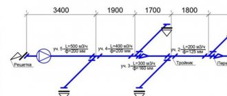
Schematic flow diagrams of heating points
The need to heat a home and prepare hot water for domestic needs becomes especially important in the harsh climate of Russia, where almost throughout its entire territory the period with outside air temperatures below 0 °C lasts about six months, and in some areas (for example, Dikson) it reaches up to 267 days.
Therefore, for the purposes of heat supply to buildings (for heating, ventilation and hot water supply), it is necessary to burn more than 30% of all fuel produced in the country. The most rational use of fuel and energy resources is made possible by centralized heat supply systems that cover cities and other large populated areas in Russia. Centralized heating supply in Russia has already celebrated its 120th anniversary. Currently, in terms of its scale, the country ranks first in Europe and second in the world (after the USA).
The centralized heat supply system consists of a source of thermal energy, pipeline heating networks and points of transformation of thermal energy and its distribution between consumers. The sources of thermal energy in centralized heat supply systems are thermal power plants (CHP), district thermal stations (RTS) or quarterly thermal stations (CTS). District heating systems, in addition to the types and characteristics of thermal energy sources, differ in the type of coolant, the method of connecting internal hot water supply systems (hereinafter referred to as hot water supply) and the number of pipes for transporting the coolant.
District heating system.
The main type of coolant in district heating systems is hot water with temperatures up to 150 °C and pressure up to 25 bar. Steam is practically not used as a coolant. It is sometimes used in heat supply systems of industrial enterprises, where it is simultaneously supplied for technological needs.
Depending on the method of connecting DHW systems to heating networks, centralized heat supply can be implemented using a closed scheme (tap water is heated in water-water heaters by the coolant of the heating system) or open (water for DHW purposes comes directly from heating networks).
Despite a number of significant shortcomings, open heat supply systems operate in a number of Russian cities. At the same time, at present, during the new construction of heat supply systems, the practice is to abandon the open circuit, and during reconstruction, a systematic transition to centralized preparation of hot water in heaters of heating points is practiced.
Of the possible variety of water heating networks (one-, two- and multi-pipe), two-pipe networks are the most widespread. Multi-pipe heating networks are a set of two-pipe networks for each individual type of consumer. Such networks (usually four-pipe for heating and hot water systems) are used for intra-block distribution of coolant and hot water from central heating points existing in a number of cities to individual buildings.
Heating points are the final element of the centralized heating supply system, where the connection between heating networks and consumers of thermal energy is carried out.
They are divided into individual (hereinafter ITP) for one building and central (hereinafter CTP), serving a group of buildings or several separate zones of one multifunctional structure.
In the structure of the centralized heat supply system that has developed since the middle of the last century, the supply of heat energy to consumers in the housing and communal services sector is carried out, as a rule, through separate quarterly central heating points with IHP located in each separate building. In recent years, a mixing pump unit has begun to be installed in ITPs for automatic control of the heating system. In this case, the ITP is sometimes called AUU (automated control unit). However, ever-increasing requirements for the quality of heat supply have determined a new technical policy, which provides for the abandonment of central heating stations and the transition to connecting subscribers to the heating network through individual heating points located directly in buildings, including the preparation of hot water in them for DHW systems via a closed circuit. scheme.
A modern heating point is a set of heating and pumping equipment in combination with electrical and hydraulic means of complex automation, ensuring the maintenance of comfortable air parameters in heated rooms of buildings and water temperature in the hot water system, the operation of engineering systems in an unattended and trouble-free mode, heat consumption metering, energy saving and, as a result, environmental protection.
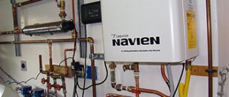
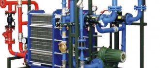
An example of a heating point.
The heating point receives coolant, converts it, distributes it between consumers, and accounts for heat consumption, while automatically providing:
- necessary parameters of the coolant in heating and ventilation systems to maintain the required temperature conditions in the serviced premises;
- water temperature in the DHW system;
- coordination and stabilization of hydraulic modes in heating networks and heat consumption systems.
All these tasks can be implemented to a large extent by automating the heating point. The result of their implementation will be not only the provision of comfortable indoor conditions and hot water parameters, but also real energy consumption savings at the level of 30–35% on an annual basis and 60–70% during transition periods when the outside air temperature exceeds 0 °C, as well as a reduction emissions of combustion products of saved fuel into the atmosphere.
Technological schemes of heating points vary depending on:
- on the type and number of heat consumers simultaneously connected to them - heating systems, hot water supply, ventilation and air conditioning (hereinafter referred to as ventilation);
- on the method of connecting the hot water supply system to the heating network - open or closed heat supply system;
- on the principle of heating water for hot water supply with a closed heating system - one-stage or two-stage scheme;
- on the method of connecting heating and ventilation systems to the heating network - dependent, with the supply of coolant to heat consumption systems directly from heating networks, or independent - through water heaters;
- on the temperature of the coolant in the heating network and in heat consumption systems (heating and ventilation) - the same or different (for example, 95–95 or 150–95 °C);
- from the piezometric graph of the heating system and its relationship to the elevation and height of the building;
- from requirements to the level of automation;
- from private instructions of the heat supply organization and additional customer requirements.
An example of a technological diagram of an automated heating point with a closed heat supply system and dependent connection of the heating system to the heating network.
An example of a technological diagram of an automated heating point with an open heat supply system and independent connection of the heating system to the heating network.
In accordance with the requirements of regulatory documents, the main functions of a heating point are:
- transformation of the type or parameters of the coolant;
- regulation of heat consumption in heating and ventilation systems;
- maintaining the temperature of hot water in the DHW system;
- ensuring a constant differential pressure across control valves or before heat consumption systems;
- limiting the maximum consumption of network water at the consumer;
- filling and replenishing heat consumption systems when they are independently connected to the heating network;
- control of circulation and make-up pumps;
- accounting of heat and water consumption.
In this regard, the heating point is divided into a number of functional units:
- I. heating network input unit;
- II. heat consumption metering unit;
- III. unit or separate devices for matching pressure and limiting coolant flow;
- IV. ventilation system connection unit;
- V. hot water preparation unit for the DHW system
- VI. coolant preparation units for heating and ventilation systems;
- VII. make-up unit (based on the number of closed heat consumption circuits).
Depending on the adopted technological scheme of the heating point, the type of units used, their number and combination can vary widely. At the same time, nodes for the input of the heating network, heat consumption metering and pressure coordination are a mandatory accessory of any heating point.
Basic requirements for functional units of a heating point
Input node (I).
The nominal diameter of the input unit, regardless of the coolant flow rate, must be at least 32 mm.
The input unit is equipped with:
- steel, usually welded shut-off valves (ball valves). At the request of the customer and in agreement with the heat supply organization, the use of flanged fittings is allowed;
- mesh filters (on pipelines DN 32–50 - coupling brass at coolant temperatures up to 110 °C or steel at temperatures up to 150 °C), on pipelines DN 40–300 - flanged cast iron at coolant temperatures up to 150 °C).
The use of mesh filters does not exclude the installation before them (along the flow of the coolant) of a subscriber mud pan to protect the filter mesh from damage by large solid inclusions in the coolant.
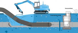
In order to clean the coolant when filling heating and ventilation systems, as well as when supplying water to the DHW system from the return pipeline of the heating network to an open heating system, it is recommended to provide a reversible bypass with an additional dirt trap and filter in the input unit.
Heat metering unit (II).
The heat consumption metering unit (hereinafter referred to as the “metering unit”) is part of the heating point, but is being developed in a separate part of the project. The design of the metering unit must be carried out in accordance with the requirements of the “Rules for commercial metering of thermal energy and coolant”.
Based on the readings of flow meters and thermal converters, the heat calculator calculates the actual heat consumption. Pulse signals from flow meters can also be used to introduce restrictions on the maximum coolant flow. When choosing a flow meter, it is necessary that the actual coolant flow does not go beyond its dynamic range. In the process of designing a heat consumption metering unit and a heating point as a whole, pressure losses in flow meters should be taken into account. Electric power devices with a power of more than 250 W, which can be a source of interference, should not be located near the flow meters (closer than 0.5 m).
Pressure matching unit (III).
The pressure matching unit is designed to ensure the operation of all elements of a heating point, heat consumption systems, as well as heating networks in a stable and trouble-free hydraulic mode.
The equipment of the unit allows:
- maintain constant differences in coolant pressure on the actuators of control devices of heat consumption systems;
- ensure the coolant pressure in the pipelines within the limits acceptable for the system elements and the heating point itself;
- ensure that systems are filled with coolant and protect them from emptying;
- ensure that the superheated coolant does not boil over at the upper points of heat consumption systems;
- if necessary, limit the maximum coolant flow rate;
- carry out automatic hydraulic balancing of heating networks.
Often, with complex piezometers of the heating network, in cases of dependent connection of heat consumption systems, it is necessary to protect them from emptying and boiling of the coolant, and to increase the available pressures of the heating network to ensure circulation of the coolant. Such problems are technically solvable, but require the use of additional devices: booster pumps, pressure regulators, automatic shut-off valves, etc.
At the same time, all known methods of protecting heat consumption systems from unfavorable hydraulic operating conditions of heating networks and the devices used, even from the most well-known manufacturers, are not completely reliable and do not exclude their trouble-free operation.
Considering the feasibility of using the simplest pressure matching devices in heat supply and heat consumption systems, as well as in order to increase their reliability, safety and stability, heating and ventilation systems of residential and public buildings should be connected to the heating network, as a rule, according to an independent circuit, through heat exchangers.
Dependent connection of systems to the heating network may be used:
- when the calculated temperatures of the coolant in the supply pipeline of the heating network $T_1$ and the heating or ventilation systems of buildings $T_{O1}$ coincide, for example, when supplying heat from heating boiler houses, $$T_1 = T_{O1};$$
- in case of connecting buildings to an existing central heating substation with heat exchangers for heating and ventilation systems;
- for systems of social class residential buildings, as well as public buildings, with a height of up to 5 floors. At the same time, for all systems dependently connected to the heating network, the following conditions must be simultaneously met:
- pressure in the supply and return pipelines of the heating network $P_1$ and $P_2$, as well as static pressure $P_{st}$ should not exceed the conditional pressure $P_y$ for all system elements, $$P_1(P_2, P_{st})
- static pressure in the heating network $P_{st}$ and pressure in its return pipeline $P_2$ must be no less than the pressure required to fill heat consumption systems, $$P_{st}(P_2) ≥ (0.1 h_{syst} + 0.5);$$ where: $P_{st}$ and $P_2$ - pressure in bar; $h_{syst}$ is the height of the heat consumption system above the level of the return pipeline of the thermal input into the building in m.
- it was ensured that the coolant superheated above 100 °C did not boil up at the top point of the heat consumption systems, that is, its excess pressure at the outlet of the heat point $P_{O1}$ must be no less than that determined by the formula: $$P^{ext}_{01} ≥ (0.1·h_{syst} + Р_{us} + 0.5),$$ where: $Р^{g}_{01}$ is pressure in bar; $h_{syst}$ is the height of the heat consumption system above the level of the return pipeline of the thermal input into the building in m; $P_{us}$ is the excess pressure of saturated water vapor at temperature $T_{11}$.
Choosing a method for connecting heating and ventilation systems to the heating network.
Example.
Given:
- Single-pipe heating system with an overhead supply line.
- The coolant temperature at the entrance to the system is $T_{O1} = 105$ °C.
- The height of the heating system above the heat point mark is $h_{syst} = 70$ m.
It is necessary to determine the pressure of the coolant at the outlet of the heating point, ensuring that it does not boil in the supply pipeline of the system laid in the attic.
Solution:
According to the formula
$$P_{01} ≥ 0.1·70+0.38+0.5 = 7.88 bar.$$
In the secondary circuits of heat consumption systems, when they are independently connected to the heating network, it is necessary to maintain static pressure to ensure that the systems are filled and the coolant does not boil, as for dependently connected systems. Static pressure is maintained using a make-up system. The conditions for connecting heating and ventilation systems to the heating network are illustrated in the figure.
Maintaining constant pressure drops on the control valves of heat consumption systems is currently a prerequisite for stabilizing hydraulic conditions in external heating networks and ensuring optimal operation of control devices in heat consumption systems of buildings.
It is recommended that hydraulic differential pressure regulators be installed in front of each electrically driven control valve. In exceptional cases, differential pressure regulators may be installed on a group of heat-using systems in a common pressure matching unit. Usually a single regulator is provided in front of the heating and hot water system.
For a group of ventilation units with their dependent connection to the heating network without changing the parameters of the coolant, it is recommended to provide an independent pressure differential regulator in the pressure matching unit. In this case, the heat supply system of ventilation units should be connected to the pipelines of the heating point before the differential pressure regulator intended for other heat consumption systems.
This is explained by the difference in the hydraulic operating modes of ventilation units and heating and hot water systems.
It is also recommended to install a separate differential pressure regulator with an open heating system in front of the direct-acting temperature regulator in the DHW mixing unit.
Mixing unit for DHW with an open heating system.
The differential pressure regulator, depending on the functions performed, can be located on the supply or return pipeline of the heating system.
The preferred location for the differential pressure regulator is on the supply pipeline to protect the equipment of the heating point and heat consumption systems from increased pressure from the heating network.
At the request of the heating supply organization, combined differential pressure regulators with automatic limitation of coolant flow can be supplied.
Ventilation system connection unit (IV).
Ventilation systems are connected to the pipelines of the heating point both in a dependent and independent manner (via a water heater), as a rule, to a pressure matching unit common to other systems. The choice of connection method depends on a number of conditions that determine the ventilation equipment used and its location along the height of the building, coolant parameters (temperature and pressure), as well as the requirements of heat supply organizations and customer wishes.
Dependent connection of ventilation systems can be performed without changing the parameters of the coolant (its temperature) or with a change.
In previous years, domestic ventilation units located in the lower part of the building were usually supplied with superheated coolant, for example, at a temperature of 150 °C without changing its parameters. A reduction in parameters was provided only for appropriate fire safety or technological requirements, as well as for air heaters for the second heating of central air conditioners and air closers.
Modern equipment, as well as the practice of high-rise construction, often dictate the need to convert the coolant temperature for ventilation units. For this purpose, a central pump mixing unit is used for dependent connection of ventilation systems to the heating network or an independent connection unit with a water heater. The choice of coolant parameters and the method of connecting its preparation unit to the heating network are determined when designing the ventilation system.
Automation of pump mixing units and water heaters for ventilation units is similar to the automation of connection units for heating or hot water systems using electronic temperature controllers.
DHW system connection unit (V). Regardless of the type of heating system (open or closed), it is recommended to prepare hot water for domestic and drinking needs using a closed circuit in plate water-water heaters.
Mixing units for preparing hot water can only be preserved at the justified request of the heat supply organization during the reconstruction of existing buildings in the existing open heat supply system.
With a closed heat supply system, heating of tap water for domestic hot water is usually carried out in high-speed water heaters. It is recommended to use plate water heaters as water heaters in modern hot water systems. For small buildings, as well as in order to ensure a guaranteed supply of hot water (at the customer’s request), the use of capacitive water heaters is allowed.
High-speed water heaters can be connected to the heating system using a single-stage parallel or two-stage mixed circuit. With a two-stage scheme, in the cold season, tap water is first heated by the return coolant after the heating system in the first stage, and then brought to the required temperature in the second stage by the primary coolant from the heating network. During the warm period of the year, tap water is heated only by the network coolant, which at this time passes sequentially through both stages of the water heater.
The choice of a one- or two-stage scheme is made depending on the ratio of the maximum thermal load on the DHW system to the calculated thermal power of the heating system. As required by regulatory documents, when the ratio $Q_{DHW} / Q_o$ is in the range of more than 0.2 or less than 1, water heaters should be connected to the heating network using a two-stage scheme, and outside the specified range - using a single-stage scheme. However, modern plate water heaters, equipped with reliable automation, are able to provide efficient heating of water without increasing the temperature of the coolant returned to the heating network, and with a single-stage scheme.
With an open heating system, water is supplied to the hot water system, depending on its required temperature, in different proportions directly from the supply and return pipelines of the heating network.
In this case, a straight-through control valve with various electric drives is used as a control device.
To prevent unauthorized flow of coolant from the supply pipeline to the return pipeline, a check valve is installed on the latter before the mixing point.
DHW systems, as a rule, provide for the circulation of water in pipelines and its heating in the absence of water consumption in order to ensure the required temperature at any time at each water tap. In a closed heating system, circulation through the DHW pipeline system and the water heater is carried out using a pump. With a two-stage water heating scheme, circulation is carried out through the second stage of the water heater. A pump is also used to circulate water in the DHW circuit with an open heating system.
On the circulation risers of the internal hot water system, it is advisable to install thermostatic balancing valves such as MTCV (not presented in the manual) or FJV, which stop circulation in the risers when the hot water temperature in them is sufficient. In this case, in order to save energy, it is recommended to use a circulation pump with a pressure-controlled drive (frequency converter).
Heating system connection unit (VI).
At the heating point of a building, the connection of the water heating system to centralized heating networks can be carried out according to dependent or independent schemes. With a dependent connection scheme, the coolant from centralized heating networks is used directly in the heating system. With an independent connection scheme, a heat exchanger is used to separate the coolants of the heating system and heating networks. The priority is the dependent circuit, as it is the cheapest and easiest to install and operate. An independent connection scheme is used when the hydrostatic pressure at the input of the heating network to the heating point of the building is insufficient or high for the operating heating system.
Maintaining a constant pressure difference on a two-pipe heating system. a – using a pump with a VLT frequency converter, b and c – using a bypass valve.
Feeding unit (VII).
Closed circuits of heating and ventilation systems independently connected to the heating network must be equipped with a make-up unit, the devices of which ensure guaranteed filling of the system with water, maintaining pressure to ensure that the coolant does not boil over with a temperature above 100 °C, and compensating for the increase in the volume of water as a result of its heating.
Filling and top-up of heat consumption systems should only be carried out using a prepared one from the return pipeline of the heating network. Topping up with water from a tap is not allowed.
The heating (ventilation) system recharge unit when it is independently connected to the heating network: a) with a recharge solenoid valve and a closed expansion vessel; b) a fragment with a make-up hydraulic pressure regulator “after itself” and a closed expansion vessel; c) a fragment with a make-up solenoid valve and a discharge hydraulic pressure regulator “to itself” (without an expansion vessel); d) a fragment with a make-up hydraulic pressure regulator “behind itself” and a discharge pressure regulator “before itself” (without an expansion vessel).
When the pressure in the return pipeline of the heating network $P_2$ is insufficient for make-up, in addition to the electrical devices, a make-up pump must be installed.
It is recommended to give preference to recharge units with electrical components.
Control of the electrical devices of the recharge unit should, as a rule, be provided by the general controller of the heating point.
Hydraulic regulators can only be used in pumpless feed units for small heating points of individual residential buildings or in large central heating stations with a load of more than 5 MW.
The hydraulic regulator, having a normally open valve, maintains the required pressure in the system, closing the make-up when it increases.
In order to compensate for the thermal expansion of water, modern heating points require the installation, as a rule, of closed expansion vessels.
Their capacity is selected depending on the calculated parameters of the coolant, the volume and required pressure of water in the heat consumption system according to the methods of the vessel manufacturers.
Closed expansion vessels reduce the risk of emergency leaks and losses of coolant, and eliminate saturation of the coolant with atmospheric oxygen.
In cases where the installation of expansion vessels is not possible (for example, due to their size in high-power systems), but the pressure in the return pipeline of the heating network is sufficient to carry out make-up without pumps, it is allowed to use make-up units with the discharge of coolant from the system, if it is exceeded pressure above the set value, back into the return pipeline of the heating network through a normally closed pressure regulator “to itself”.
This method of protecting the heat consumption system from unacceptable pressures can be used both with electric make-up devices and with hydraulic regulators.
The initial data for selecting recharge unit devices are:
- estimated flow of make-up water;
- maximum (calculated) coolant temperature at the top point of the heat consumption system;
- coolant pressure in the return pipeline of the heating network;
- required minimum static pressure in the heat consumption system;
- maximum permissible static pressure in the system;
- minimum pressure drop across the valves of the make-up unit.
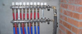
What does the CTP consist of?
Let's consider the design and equipment of the central heating station. The system is installed in a separate building. Equipment inside:
- pumps - working and standby, ensuring a constant supply of coolant even in an unforeseen situation;
- heat exchanger – heating coolant;
- temperature and pressure regulators;
- cleaning filters at the inlet and outlet of pipes;
- taps;
- control equipment that records heat consumption;
- automatic control systems;
- power supply system.
For optimal functioning of the central heating station, equipment is selected based on the area of the room and the technical parameters of the building.
Appendix B
List of sources used
- Federal Law of November 23, 2009 N 261-FZ (as amended on December 29, 2014) “On energy saving and increasing energy efficiency and on introducing amendments to certain legislative acts of the Russian Federation”
- Rules for the technical operation of thermal power plants (approved by order of the Ministry of Energy of the Russian Federation dated March 24, 2003 N 115)
- Federal Law of July 27, 2010 N 190-FZ (as amended on December 29, 2014) “On Heat Supply” (as amended and supplemented, entered into force on March 3, 2015).
- Presentation of the report at the meeting of the City Non-Departmental Commission on March 27, 2015. “Results of monitoring the equipping of apartment buildings in St. Petersburg with metering units as of March 27, 2015”
- JSC "SHAD-International" Description of a water jet with an adjustable nozzle (VARS). Patent No. 2151918. https://www.shad-in.ru.
- Methodology for determining the need for fuel, electrical energy and water in the production and transmission of thermal energy and coolants in municipal heating systems. (approved by the State Construction Committee of the Russian Federation on August 12, 2003)
Maintenance
Once a week, the management of the operating organization inspects the central heating point. And once every three months - the technical director of the heat supply company. Check:
- heating fluid parameters;
- condition of heat exchangers, instrumentation, and other equipment;
- condition of pipe connections, thermal insulation;
- correct settings of electronic units;
- condition of electrical panels;
- energy efficiency of the system;
- coolant leaks.
During the inspection, the condition of the equipment is determined, damaged and worn elements are identified. If necessary, equipment is dismantled and replaced. Maintenance work is carried out in protective clothing to avoid burns. Operation of faulty equipment is prohibited.
In conclusion, we will give an exact answer to the question of what a central heating station is - this is a set of equipment for the preparation and distribution of hot water. The need is caused by the fact that at the exit from the central boiler room the coolant is too hot to be supplied to consumers. Therefore, it passes through the central heating station, which creates the required water parameters. You may also be interested in flushing accessories and seals for heat exchangers.
ITP for different consumption purposes
Being equipped for heating, the IHP has an independent circuit in which a plate heat exchanger with 100% load is installed. Pressure loss is prevented by installing a double pump. Make-up is carried out from the return pipeline in the heating networks. Additionally, the TP is equipped with metering devices, a DHW unit if other necessary components are available.
ITP intended for hot water supply is an independent circuit. In addition, it is parallel and single-stage, equipped with two plate heat exchangers loaded at 50%. There are pumps that compensate for the decrease in pressure, and metering devices. The presence of other nodes is assumed. Such heat points operate according to an independent scheme.
This is interesting! The principle of district heating for a heating system can be based on a plate heat exchanger with 100% load. And the DHW has a two-stage circuit with two similar devices, each loaded by 1/2. Pumps for various purposes compensate for the decreasing pressure and recharge the system from the pipeline.
For ventilation, a plate heat exchanger with 100% load is used. DHW is provided to two such devices loaded at 50%. Through the operation of several pumps, the pressure level is compensated and replenishment is provided. Addition - accounting device.
ITP of an apartment building
An automated individual heating point in a multi-storey residential building transports heat from central heating stations, boiler houses or combined heat and power plants (CHP) to heating, hot water supply and ventilation. Such innovations (automatic heating point) save up to 40% or more of thermal energy.
Attention! The system uses a source - the heating networks to which it is connected. The need for coordination with these organizations.
A lot of data is required to calculate modes, loads and savings results for payments in housing and communal services. Without this information, the project will not be completed. Without approval, the ITP will not issue permission to operate. Residents receive the following benefits.
- Greater accuracy of temperature maintenance devices.
- Heating is carried out with a calculation that includes the state of the outside air.
- The amounts for services on housing and communal services bills are being reduced.
- Automation simplifies facility maintenance.
- Reduced repair costs and personnel numbers.
- Finances are saved on the consumption of thermal energy from a centralized supplier (boiler houses, combined heat and power plants, central heating stations).
Where does the noise come from?
Vibration of pump casings, boilers and pipes creates airborne noise. It enters the apartment via a frame. When equipment comes into contact with a building, vibrations are created, which are transmitted from the metal to the concrete, and then to the living space. The noise transmission channels are: metal studs on which the pipes are held; brackets near the walls along the pipe laying; non-vibration-insulating mounting of equipment to the floor.
However, when using modern heating units, complete noise insulation is ensured. The noise does not disturb the peace of residents and complies with all SNiP (building codes and regulations). Thus, noise pollution in the area is reduced. This result is achieved due to the fact that:
- Pumps are connected to pipelines with flexible anti-vibration rubber inserts;
- The pumps have a low noise level;
- Rubber-metal supports are used between the pump frame and the floor;
- There is a gap between the surface of the insulation pipe structure and the building structure. Tight sealing of pipes into the walls of a building is unacceptable.