Natural ventilation of a room is the spontaneous movement of air masses due to the difference in its temperature conditions outside and inside.
This type of ventilation is divided into ductless and ducted; it is relatively capable of continuous and periodic operation.
The systematic movement of transoms, vents, doors and windows implies the ventilation procedure itself.
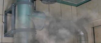
Ductless ventilation is formed on a stable basis in industrial-type rooms with noticeable heat emissions, organizing the required frequency of exchange of air masses in the middle of them, this process is called aeration.
In private and multi-storey buildings, a natural duct-type ventilation system is used more often, in which the ducts are located in a vertical position
in specialized blocks, shafts or located in the walls themselves.
What is natural ventilation
No electrical appliances are needed to arrange natural ventilation
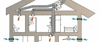
The concept of a natural ventilation system means that its operation does not require any mechanical devices that could force the movement of air currents.
Air moves under the influence of natural factors. This ventilation design is used in private and multi-storey buildings. Since in large rooms it does not always cope with its functions, it is necessary to equip additional structures that supply and exhaust air.
Goals and objectives
In an apartment, dust, moisture, and pathogenic microorganisms constantly accumulate in the air. If its circulation does not occur, cases of respiratory diseases in the house become more frequent, and the indoor microclimate worsens. Exceeding the permissible humidity level negatively affects construction and finishing materials, reducing their service life, worsening their appearance and technical characteristics.
Natural supply and exhaust ventilation is especially important in rooms such as the kitchen, bathroom and toilet. The system performs the following functions:
- softens temperature conditions;
- eliminates harmful microorganisms and dust from the room;
- prevents the appearance of mold and mildew that develop due to excess humidity levels;
- removes unpleasant odors.
Natural air conditioning is present in any room, regardless of the construction material or number of floors of the building.
Calculation of the cross-section of the air duct for mechanical (forced) ventilation?
The cross-section of a rectangular and/or round air duct is calculated using two known parameters: air exchange in the room and flow speed .
Air exchange throughout the room can be replaced by fan performance. The performance of the supply or exhaust fans is indicated by the manufacturer in the product data sheet. When designing or pre-design development, air exchange is calculated based on the multiplicity. Multiplicity (the number of times the full volume of air in a room is replaced in 1 hour) is a coefficient from regulatory documentation.
The duct flow velocity must be measured if it is an installed system . And if the project is under development, then the flow rate in the air duct is set independently. The flow speed in the air duct should not exceed 10 m/s.
How does the air exchange process work?
The main purpose of the gravity version of the air exchange device is to maintain the required microclimate. In addition to saturating the space with fresh air, it also removes exhaust air, gas combustion products, and various odors.
The efficiency of a natural ventilation system installed in a country house or country house is determined by the difference in atmospheric pressure inside and outside the house, which also depends on temperature, air humidity and wind strength.
Natural ventilation should ensure uniform supply, movement inside and removal of air flows, regardless of the number of floors of the house
Natural air exchange works as follows:
- Air from the street enters the house through open transoms and elements of window and door structures that are loosely adjacent to each other. Air flows rush inward during ventilation through slightly open plastic windows or through ventilation supply valves.
- The movement of air from one room to another and within it occurs spontaneously. To ensure that there are no obstacles to the flow, gaps are left between the floor and the doors. Their function is successfully performed by flow grilles installed in walls.
- Exhaust air leaves the house through exhaust ventilation ducts. They are located in rooms with unstable humidity/temperature - in kitchens, separate and combined bathrooms.
All city residents are very familiar with exhaust components. These are ducts connected to a public ventilation shaft. They are covered with grates that need to be cleaned periodically.
In the arrangement of a private home, the organization of natural exhaust can vary significantly. For example, this could be an vent at the top of the wall, an exhaust pipe or a hole in the ceiling with access to the ventilation duct into the attic, and from there to the street.
Heat load calculation
Calculation of the thermal load on ventilation is carried out according to the formula:
Q in = V n * k * p * C r ( t in – t nro),
in the formula for calculating the heat load for ventilation, Vn is the external volume of the building in cubic meters, k is the air exchange rate, tin is the average temperature in the building, in degrees Celsius, tnro is the outside air temperature used in heating calculations, in degrees Celsius, p is the air density , in kg cubic meter, Wed – heat capacity of air, in kJ cubic meter Celsius.
If the air temperature is below tnro , the air exchange rate decreases, and the heat consumption indicator is considered equal to Qв , a constant value.
If, when calculating the heat load for ventilation, it is impossible to reduce the air exchange rate, the heat consumption is calculated based on the heating temperature.
Heat consumption for ventilation
The specific annual heat consumption for ventilation is calculated as follows:
Q= * b * (1-E),
in the formula for calculating heat consumption for ventilation Qo is the total heat loss of the building during the heating season, Qb is domestic heat input, Qs is heat input from outside (sun), n is the coefficient of thermal inertia of walls and ceilings, E is the reduction factor. For individual heating systems 0.15 , for central heating systems 0.1 , b – heat loss coefficient:
- 1,11 – for tower buildings;
- 1,13 – for multi-section and multi-entry buildings;
- 1,07 – for buildings with warm attics and basements.
Natural ventilation device
To implement a ventilation device that operates on the gravity principle, you need to use some elements from the list below:
- Air access can be provided through cracks and leaky enclosing structures. In non-residential premises, holes, dormer windows and vents are specially made for this purpose.
- Windows in micro-slot or conventional ventilation mode and open vents provide an influx of fresh air.
- Wall or window inlet valves allow air to enter the room when sealed windows are closed.
- Sometimes an air duct system is laid for this purpose.
- Ventilation shafts and ducts are installed in apartment buildings and private buildings to remove stagnant air from the premises.
- If the house has a fireplace or stove, the chimney can simultaneously remove smoke and used air masses from the room.
- Deflectors allow you to increase draft in the exhaust pipe.
- Ventilation grilles cover the ventilation duct openings in the room. There are grilles that are installed outdoors. They protect the channel from debris, sediment, insects, rodents and birds getting into it.
- Anemostats are special grilles that differ from the traditional version in appearance and operating principle.
- Sometimes, for ventilation, transfer valves are installed in the door leaf. Instead, the same functions can be performed by the gap under the door.
- A check valve is mounted on air ducts to protect against reverse draft.
Wall inlet valves
Wall valves allow air to pass through, but provide good protection from street noise. They eliminate high humidity and stuffiness in the room. There is a damper to regulate the air flow. After the arrival of cold air masses, they mix with warm ones and provide a comfortable temperature in the house.
Attention! Supply valves are effective only if the ventilation ducts are working properly.
Wall valves are installed at a distance of 1.5-2 m from the floor. Retreat at least 30 cm from the slope of the window opening, otherwise the partition will freeze. They can also be mounted under the windowsill near the radiator so that cold air from the street is immediately heated.
Valves for windows
Supply valves on windows protect structures from fogging and allow rooms to be ventilated. There are several types of window valves: some are installed without drilling the frame or sash, others require drilling holes, but are more efficient. There are also handle valves, they can be equipped with strainers.
Ventilation ducts
Ventilation ducts are made in the wall of a house during its construction. The standard size of ventilation ducts is 140x140 mm. Channels must be made in the bathroom, toilet and kitchen. Moreover, in an apartment building there are separate channels from each apartment. It is prohibited to make one ventilation duct from several rooms.
Hoods
Deflectors, louvres, draft amplifiers and check valves are installed on ventilation ducts and air ducts in order to increase the efficiency of the system and protect against the following undesirable phenomena:
- overturning traction;
- low ventilation efficiency;
- blowing out heating equipment;
- debris getting into the ventilation ducts.
Calculate the diameters of ventilation ducts
Further calculations are somewhat more complicated, so we will provide each step with examples of calculations. The result will be the diameter and height of the ventilation shafts of our one-story building.
We distributed the entire volume of exhaust air into 3 channels: 100 cubic meters. The hood in the kitchen is forcibly removed when the stove is turned on, the remaining 271 cubic meters goes through two identical shafts naturally. The flow rate through 1 air duct will be 271 / 2 = 135.5 m³/h. The cross-sectional area of the pipe is determined by the formula:
- F – cross-sectional area of the ventilation duct, m²;
- L – exhaust flow through the shaft, m³/h;
- ʋ—flow speed, m/s.
Reference. The air speed in the natural ventilation channels is in the range of 0.5–1.5 m/s. We take the average value as the calculated value - 1 m/s.
How to calculate the cross-section and diameter of one pipe in the example:
- We find the diameter size in square meters F = 135.5 / 3600 x 1 = 0.0378 m².
- From the school formula for the area of a circle, we determine the diameter of the duct D = 0.22 m. We select the nearest larger air duct from the standard range - Ø225 mm.
- If we are talking about a brick shaft embedded inside the wall, then the size of the ventilation duct 140 x 270 mm will fit the found cross-section (good coincidence, F = 0.0378 sq. m.).
Brick shafts have strictly fixed dimensions - 14 x 14 and 27 x 14 cm.
The diameter of the outlet pipe for a household hood is calculated in the same way, only the flow speed forced by the fan is assumed to be greater - 3 m/s. F = 100 / 3600 x 3 = 0.009 m² or Ø110 mm.
The main advantages and areas of use of such ventilation
Ventilation of this type works on the basis of the difference in temperature and air pressure outside and inside the room. Such ventilation does not require the use of fans and other additional devices necessary for mechanical ventilation. Air penetrates through special openings, windows, vents, cracks and leaves the room through them.
Natural ventilation is suitable for buildings of any type. It makes sense to use additional devices only in cases where natural ventilation cannot cope with the tasks assigned to it.
Among the main advantages of natural ventilation systems are:
Schemes for organizing air exchange in rooms.
- Simplicity of arrangement, which does not require the use of special devices.
- No large financial investments.
- High efficiency with a well-prepared project.
- There is no need to hire professionals to install the ventilation system.
Natural impulse ventilation comes in several types, namely:
- Unorganized, i.e. spontaneous. In the case of such ventilation, air is supplied and removed from the room solely due to the difference in temperature and pressure, as well as wind speed.
- Organized. Involves the installation of special ventilation holes. They are located at different levels and have different cross-sections. It is a more effective way to organize air exchange with natural impulses.
In the process of installing ventilation with natural impulse, the most important thing is to draw up the right design. The efficiency of air exchange directly depends on the correctness of the calculation. The slightest mistakes can lead to a decrease in the efficiency of the system, which can lead to many negative consequences such as air stagnation, increased humidity to unacceptable levels, the appearance of mold, etc.
How to simplify the task - tips
You could see that calculations and organization of air exchange in a building are quite complex issues. We tried to explain the methodology in the most accessible form, but the calculations still look cumbersome for the average user. Let's give some recommendations for a simplified solution to the problem:
- The first 3 stages will have to be completed in any case - find out the volume of emitted air, develop a flow pattern and calculate the diameters of the exhaust air ducts.
- Take the flow velocity to be no more than 1 m/s and use it to determine the channel cross-section. It is not necessary to master aerodynamics - calculate the diameters correctly and simply bring the air ducts to a height of at least 2 meters above the intake grilles.
- Inside the building, try to use plastic pipes - thanks to their smooth walls, they practically do not resist the movement of gases.
- Ventilation ducts laid in a cold attic must be insulated.
- Do not block the mine exits with fans, as is customary to do in apartment toilets. The impeller will not allow the natural hood to function normally.
To increase the flow, install adjustable wall valves in the rooms, get rid of all the cracks from where cold air can enter the house uncontrollably.
Why is it necessary to calculate the diameters of air ducts? Industrial ventilation is designed taking into account several facts, all of which are significantly influenced by the cross-section of the air ducts.
- Air exchange rate. During the calculations, the features of the technology, the chemical composition of the harmful compounds released, and the dimensions of the room are taken into account.
- Noisy. Ventilation systems should not worsen working conditions in terms of noise. The cross-section and thickness are selected in such a way as to minimize the noise of air flows.
- Efficiency of the general ventilation system. Several rooms can be connected to one main air duct. Each of them must maintain its own ventilation parameters, and this largely depends on the correct choice of diameters. They are selected in such a way that the size and capabilities of one common fan can provide regulated system modes.
- Economical. The smaller the energy losses in the air ducts, the lower the electrical energy consumption. At the same time, it is necessary to take into account the cost of the equipment and select economically feasible dimensions of the elements.
An effective and economical ventilation system requires complex preliminary calculations; only specialists with higher education can do this. Currently, plastic air ducts are most often used for industrial ventilation; they meet all modern requirements and make it possible to reduce not only the dimensions and cost of the ventilation system, but also the cost of its maintenance.
Air duct diameter calculation
To calculate dimensions, you need to have initial data: the maximum permissible speed of air flow and the volume of air passed per unit of time. This data is taken from the technical characteristics of the ventilation system. The speed of air movement affects the noise of the system, and it is strictly controlled by sanitary government organizations. The volume of air passed must correspond to the parameters of the fans and the required exchange rate. The calculated area of the air duct is determined by the formula Sc = L × 2.778 / V, where:
Sc – cross-sectional area of the air duct in square centimeters; L – maximum air supply (flow rate) in m3/hour; V – design operating air flow speed in meters per second without peak values; 2.778 is the coefficient for converting various metric numbers to diameter values in square centimeters.
Ventilation system designers take into account the following important dependencies:
- If it is necessary to supply the same volume of air, reducing the diameter of the air ducts leads to an increase in air flow speed. This phenomenon has three negative consequences. First, an increase in air speed increases noise, and this parameter is controlled by sanitary standards and cannot exceed permissible values. Secondly, the higher the air speed, the higher the energy losses, the more powerful the fans are needed to ensure the specified operating modes of the system, the larger their sizes. Third, the small dimensions of the air ducts are not able to properly distribute flows between different rooms.
Dependence of air speed on the diameter of the air duct
- An unjustified increase in the diameters of air ducts increases the price of the ventilation system and creates difficulties during installation work. Large sizes have a negative impact on the cost of system maintenance and the cost of manufactured products.
The smaller the diameter of the air duct, the faster the air speed. This not only increases noise and vibration, but also increases air flow resistance. Accordingly, to ensure the required calculated exchange rate, it is necessary to install powerful fans, which increases their size and is economically unprofitable at current prices for electrical energy.
With increasing diameters, the above problems disappear, but new ones appear - the complexity of installation and the high cost of large-scale equipment, including various shut-off and control valves. In addition, large-diameter air ducts require a lot of free space for installation; holes have to be made for them in main walls and partitions. Another problem is that if they are used for heating rooms, then the large size of the air duct requires increased costs for thermal protection measures, which further increases the estimated cost of the system.
In simplified versions of the calculations, it is taken into account that the optimal speed of air flows should be in the range of 12–15 m/s, due to this it is possible to slightly reduce their diameter and thickness. Due to the fact that main air ducts in most cases are laid in special technical channels, the noise level can be neglected. In branches that go directly into the premises, the air speed is reduced to 5–6 m/s, thereby reducing noise. The volume of air is taken from the SaniPin tables for each room, depending on its intended dimensions.
Problems arise with long-distance main ducts in large plants or in systems with many branches. For example, with a standardized air flow of 35,000 m3/h and an air flow speed of 8 m/s, the diameter of the air duct must be at least 1.5 m with a thickness of more than two millimeters; when the air flow speed increases to 13 m/s, the dimensions of the air ducts are reduced to 1 m .
Pressure loss table
The diameter of the air duct branches is calculated taking into account the requirements for each room. It is possible to use the same dimensions for them, and to change the air parameters, install different adjustable throttle valves. Such options for ventilation systems allow you to automatically change performance indicators taking into account the actual situation. There should be no drafts in the premises caused by ventilation. Creating a favorable microclimate is achieved through the correct choice of installation location for ventilation grilles and their linear dimensions.
The systems themselves are calculated using the constant velocity method and the pressure loss method. Based on these data, the size, type and power of fans are selected, their number is calculated, installation locations are planned, and the dimensions of the air duct are determined.
Although there are many programs for ventilation calculations, many parameters are still determined the old fashioned way, using formulas. Calculation of the ventilation load, area, power and parameters of individual elements is carried out after drawing up the diagram and distribution of the equipment.
This is a difficult task that only professionals can do. But if you need to calculate the area of some ventilation elements or the cross-section of air ducts for a small cottage, you can really do it yourself.
Components of gravitational air exchange
One of the common problems with natural ventilation in a private home is the lack of fresh air entering the room. Gravity ventilation works flawlessly only when the density of the air mass outside the window is significantly higher than inside the premises. In the summer, when their density is equalized, air from the street does not flow.
In addition, serious obstacles are now being placed in the path of naturally moving air flows. The seals of windows and doors offered to consumers these days perfectly resist heat leakage, but they also do not let air in from the outside.
In order to ensure natural air flow in houses with sealed windows, it is worth installing supply valves in the wall and providing exhaust ventilation pipes with deflectors
The issue of fresh air entering rooms with practically sealed windows and doors is solved by installing ventilation supply valves. If you don’t want to install valves, you will have to purchase supply units for plastic windows or buy window packages with supply units initially built into them.
Window inlet valve
This device is also called a window ventilator. Refers to the most common options for solving the air exchange problem. The design of such a valve is mounted directly into the window profile.
The flow of incoming air through the window ventilator is directed upward so that the cold supply air mixes more effectively with the already heated air inside the room and does not cause discomfort to residents
Some valves are equipped with automatic air flow control. It is worth noting that manufacturers do not equip all ventilator models with mechanical adjustment. This can create certain problems with sudden temperature changes.
The main disadvantage of a window supply valve is its relatively low performance. Its throughput is limited by the size of the profile.
Wall exhaust or supply device
To install a wall ventilator, you need to make a through hole in the wall. The performance of such a valve is usually higher than that of a window valve. As in the case of a window supply, the incoming volume of fresh air is controlled both manually and automatically.
Wall exhaust valves are usually located at the top of the wall, where exhaust air naturally rises. Inlet valves into the wall are most often installed between the window and the radiator. They do this so that the incoming cold air also heats up.
If a wall ventilation valve is installed directly above the radiator, the flow of fresh air will spontaneously heat up before being delivered into the room
Advantages of installing a supply valve over conventional ventilation:
- Ability to regulate the flow of fresh air;
- The ability to transmit significantly less street noise;
- Availability of filters of varying degrees of air purification.
The design of the wall supply and exhaust valve does not allow moisture to penetrate into the room. Many models of these local ventilation devices often include filters for air purification.
Interior transfer grilles
In order for fresh air to freely penetrate into all parts of the house, transfer components are needed. They allow air flows to flow freely from the inlet to the exhaust, taking with them dust, animal hair, carbon dioxide, unpleasant odors, household fumes and similar inclusions suspended in the air mass.
The flow occurs through open doorways. However, it should not stop even if the interior doors are closed. To do this, leave a gap of 1.5-2.0 cm between the floor and the interior door leaf.
In order for fresh air to move freely to the hood and wash all rooms, transfer grilles are installed in the door leaves. If they are not there, then a gap of up to 2 cm is left between the floor plane and the canvas.
Also for these purposes, transfer grilles are used, mounted in a door or wall. The design of such grilles consists of two frames with blinds. They are made of plastic, metal or wood.
Guide for designers SP 60. 13330.2016
This collection of rules is the main document for designers of a ventilation complex in a private house. This document establishes the rules for designing ventilation systems for all types of buildings. Here they also build on state standards for the microclimate of residential premises.
Sanitary and epidemiological indicators of residential buildings are applied according to SanPin 2.1.2.2645.
The main postulates of the normative collection
The rules require that materials for air ducts and other parts of ventilation structures be purchased only if there are certificates confirming their compliance with sanitary and hygienic requirements.
To prevent the appearance of condensation, the air ducts are thermally insulated according to SP 61.13330 standards. To protect against aggressive air components inside and outside the house, anti-corrosion materials are used or the surface of the boxes is coated with special compounds.
Thermal insulation of pipelines is used to prevent the formation of condensate and protect against the aggressive effects of chemicals contained in condensate
Installation and adjustment work is carried out in accordance with SP 73.13330.
Mechanically driven ventilation is used:
- if there is not enough natural air exchange;
- if the area is not equipped with air supply devices.
Mechanical ventilation is turned on when there is not enough natural circulation of the air mass during certain periods of time.
The ventilation system based on natural air circulation is calculated based on the difference in the density of street air at a temperature of 5° C and the density of indoor air at standard temperature in the cold season of the year.
If at the above temperatures the air is not completely renewed, supply and exhaust systems are made with mechanical stimulation.
Receiving ventilation devices
They should not be located at a distance of less than 8 m from waste collection areas, parking lots with more than three cars, highways and other sources of harmful emissions and unpleasant odors.
Reception openings for the supply part of the air exchange system are located in the area of the base or foundation of the house
In the upper zone of the building, the receiving structures are placed on the windward side. On hot days they are protected from direct sunlight and overheating.
The lower boundary of the ventilation intake compartment passes at a level of no more than 1 m from the snow surface, but not lower than 2 meters from the average ground level.
Air flow calculation
The calculation is made according to Appendix G of the current set of rules. From the calculation results, a greater value is taken that guarantees compliance with sanitary standards and safety in relation to fires and explosions. The amount of air entering the room should not be less than the minimum consumption calculated according to Appendices G and I.
Air costs are calculated separately for the summer and winter periods and the off-season using formulas G1-G7, choosing the highest value obtained:
- by excess heat;
- by weight of harmful and dangerous elements;
- by excess moisture;
- by air circulation rate;
- according to consumption per 1 person.
The minimum consumption of external air cubic meters per hour per person is given in Table I1 of Appendix I.
Rules for organizing air exchange
Air is supplied to living spaces through special distributors in the upper part of the house. Receiving chambers for air outflow are made under the ceiling of the room at least 2 m from the floor to the bottom side of the hole to remove excess heat, excess moisture and gases.
Equipment and its placement
Fans are selected based on two indicators: the resistance of the ventilation network at a given speed of the air mixture in it and the calculated air consumption. At the same time, the inflow and flow of air through loose fits of parts in factory devices and air ducts is taken into account as required by clause 7.11.8.
The air flow is forced to move by a fan. Axial models are installed in the exhaust and supply openings to provide local ventilation
Transit distances of air ducts are designed in accordance with GOST REN 13779 according to class B tightness, in other cases according to class A.
Air suction and leakage through fire dampers and ventilation ducts are taken in accordance with SP 5.13130.2009, to comply with Federal Law requirements dated July 22, 2008. No. 123-FZ “TR on industrial safety requirements”.
Cleaning filters are selected taking into account the duration of operation, the amount of dust collected, and the degree of air purification. Outdoor air distributors must have devices for regulating the air flow vector and its flow rate.
In rooms with gas installations, fans are equipped with grilles and valves with air flow regulators. Their device guarantees incomplete closure.
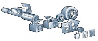
Axial and centrifugal types of fans are installed in air ducts. They stimulate flow through the system. The choice of model is determined by the volume of supplied air and the specific operation of the room
Premises for the location of ventilation equipment, including on technical floors and attics of residential buildings, are selected in accordance with the conditions of SP 54.13330 “Residential multi-apartment buildings”. The category of the premises in terms of explosion and fire hazard is determined by Federal Law No. 123-FZ.
Shape and material of air ducts
In low-rise residential buildings, combining general ventilation air ducts with a warm attic is ineffective. To prevent smoke, fire dampers and air barriers are installed on air ducts.
Ventilation ducts with limited fire resistance are made of non-combustible materials. Fire-resistant materials are also used for transit sections of ventilation systems and air ducts in rooms for placing equipment in basements and attics.
Materials with a flammability group higher than G1 are allowed:
- for air ducts of premises, except for the above;
- for flexible inserts of transit sections.
Ventilation ducts and pipes are made from unified standard parts. The use of asbestos cement in supply systems is not allowed. Air ducts must have coatings that are resistant to aggressive environments.
To assemble a duct ventilation system, pipes and fittings are made of galvanized steel and plastic.
The thickness of sheet steel for the manufacture of air ducts is selected according to Appendix K of the regulatory collection under consideration.
At a permissible temperature of no higher than 80 degrees with a round diameter:
- up to 200 mm inclusive - sheet thickness 0.5 mm;
- from 250 to 450 mm - 0.6 mm;
- from 500 to 800 mm - 07 mm;
- from 900 to 1250 mm - 1.0 mm.
For rectangular ducts:
- up to 250 mm - 0.5 m;
- from 300 mm to 1000 mm - 0.7 mm;
- from 1250 to 2000 mm - 0.9 mm.
With an established fire resistance standard of at least 0.8 mm. It is not allowed to lay transit air ducts coming from premises for other purposes through kitchens and living rooms.
Gas pipelines, cables, wires, sewer pipes are allowed to be laid at a distance of more than 100 mm from the walls of the installed air ducts. Domestic sewerage pipelines are not allowed to be placed in air exhaust shafts.
The ducts and pipes of general exhaust ventilation are mounted with a rise of 0.005 in the direction of movement of the air mass. To remove the resulting condensate, drainage devices are provided.
Specifics of energy saving and automation
For private households, saving energy resources plays a significant role.
The total energy saving when designing ventilation systems is due to:
- selection of advanced equipment;
- solving energy efficient problems;
- application of mechanical systems;
- secondary use of heat from exhaust air;
- individual approach to regulating air exchange.
Electrical installations are selected taking into account the standards of the PUE (7th edition) “Rules for the construction of electrical installations”. If there is a fire extinguishing and fire alarm system in the cottage, an automatic blocking of the power supply to the ventilation systems is designed in accordance with SP 7.13130.
In case of fire, it is planned to turn off the ventilation systems centrally or individually and turn on smoke protection. Remote control of smoke fire dampers, windows, transoms must be automated.
Types of natural ventilation
There are 3 types of natural ventilation:
- Unorganized ventilation
- Organized ventilation
- Forced ventilation
Unorganized natural ventilation
An unorganized natural ventilation system involves air entering the room and leaving it out in the most natural way. In this case, air exchange is carried out due to the difference in temperature (in the room and outside the window), wind speed and, in general, its presence, increase/decrease in atmospheric pressure. Thus, unorganized ventilation is created using windows (or vents) and doors that are periodically opened by residents for ventilation.
Organized natural ventilation
An organized natural ventilation system is represented by special openings that are created in the walls, under the ceiling and above the floor. Air flows in and out through these holes. The system of holes is called “organized” because to create such ventilation it is necessary to make an accurate calculation, taking into account the size of the room and the technical parameters of ventilation, as well as to correctly design the system of ventilation ducts and accurately implement it during the construction of the house.
Supply and exhaust natural ventilation
Supply ventilation is designed to provide an influx of fresh air from the street, exhaust ventilation is the outflow of exhaust air from the room to the outside. Depending on the tasks assigned, the emphasis can be placed either on supply ventilation or exhaust ventilation. It is important to properly implement natural ventilation, especially if no additional climate control equipment is planned to be installed. The health of household members, the service life of building and finishing materials, and the service life of the house as a whole ultimately depend on how correctly and efficiently the natural ventilation system is implemented.
General sanitary requirements in GOST 30494-2011
A collection of state-approved standards for creating a comfortable living environment in residential buildings.
Indicators for air in residential apartments:
- temperature;
- moving speed;
- proportion of air humidity;
- total temperature.
Depending on the stated requirements, permissible or optimal values are used in calculations. You can see their full composition in Table No. 1 of the above standard. A condensed example version is given below.
For a living room the following are allowed:
- temperature – 18o-24o;
- humidity percentage – 60%;
- air movement speed – 0.2 m/sec.
For kitchen:
- temperature - 18-26 degrees;
- relative humidity – not standardized;
- the speed of movement of the air mixture is 0.2 m/sec.
For the bathroom, toilet:
- temperature - 18-26 degrees;
- relative humidity – not standardized;
- air movement rate is 0.2 m/sec.
During the warm season, microclimate indicators are not standardized.
The temperature environment inside the rooms is assessed using the usual air temperature and the resulting temperature. The last value is a collective indicator of air tо and room radiation tо. It can be calculated using the formula in Appendix A by measuring the heating of all surfaces in the room. An easier way is to measure with a ball thermometer.
To correctly measure temperature data and take samples to determine the organoleptic indicators of the air mass, the direction of the flow of the supply and exhaust parts of the system should be taken into account
Air pollution inside a home is determined by the content of carbon dioxide, a product exhaled by people during breathing. Harmful emissions from furniture and linoleum are equal to an equivalent amount of CO2.
Indoor air and its quality are classified according to the content of this substance:
- Class 1 - high - carbon dioxide tolerance of 400 cm3 and below in 1 m3;
- Class 2 - average - carbon dioxide tolerance 400 - 600 cm3 per 1 m3;
- Class 3 – permissible – CO2 tolerance – 1000 cm3/m3;
- Class 2 – low – carbon dioxide tolerance of 1000 cm3 and above per 1 m3.
The required volume of outside air for the ventilation system is determined by calculation using the formula:
L = k×Ls , where
k is the air distribution efficiency coefficient, given in Table 6 of GOST;
Ls – calculated, minimum amount of outside air.
For a system without forced traction k = 1.
The following article will introduce you in detail to performing calculations to ensure ventilation of premises, which is worth reading for both construction customers and owners of problematic housing.
Advantages and disadvantages of natural ventilation
Properly designed and installed natural supply and exhaust ventilation maintains optimal air exchange conditions for human life, helps maintain his performance and strong immunity.
Benefits of natural ventilation:
- Does not require the use of complex technological equipment or connection to an energy source.
- Does not require regular maintenance or repair over a long service life.
- Does not create extraneous noise or vibration.
- It is possible to combine it with equipment for ionization, air conditioning, heating, dehumidification or humidification.
- There are no electricity costs.
The disadvantages include: low intensity of the air exchange process; lack of ability to adjust the system; insufficient speed of air masses leads to the formation of condensation and mold fungi. The maximum efficiency of natural ventilation is ensured only in the cold season and in windy weather.
Calculation of the diameter of air ducts
The diameters and cross-sections of ventilation air ducts are calculated after the general diagram of the system has been drawn up. When calculating the diameters of ventilation air ducts, the following indicators are taken into account:
- The volume of air (supply or exhaust) that must pass through the pipe in a given period of time, cubic meter;
- Air speed. If, when calculating ventilation pipes, the flow rate is underestimated, air ducts with a cross-section that are too large will be installed, which entails additional costs. Excessive speed leads to vibrations, increased aerodynamic noise and increased equipment power. The speed of movement on the inflow is 1.5 - 8 ms, it varies depending on the area;
- Ventilation pipe material. When calculating the diameter, this indicator affects the wall resistance. For example, black steel with rough walls has the highest resistance. Therefore, the calculated diameter of the ventilation duct will have to be slightly increased compared to the standards for plastic or stainless steel.
| Type of site | Flow rate, ms |
| Main pipelines | From 6 to 8 |
| Lateral layers | From 4 to 5 |
| Distribution pipelines | From 1.5 to 2 |
| Upper inlets | From 1 to 3 |
| Hoods | From 1.5 to 3 |
Table 1 . Optimal air flow speed in ventilation pipes.
When the throughput of future air ducts is known, the cross-section of the ventilation duct can be calculated:
S = R 3600 v ,
here v is the speed of the air flow, in ms, R is the air flow rate, cubic meters.
The number 3600 is a time coefficient.
Knowing the cross-sectional area, you can calculate the diameter of the round ventilation duct:
here: D – diameter of the ventilation pipe, m.
If it is necessary to calculate the diameter of a rectangular ventilation pipe, its parameters are selected based on the obtained cross-sectional area of the round pipe.
Calculation of the area of ventilation elements
Calculation of the ventilation area is necessary when the elements are made of sheet metal and it is necessary to determine the quantity and cost of the material.
The ventilation area is calculated using electronic calculators or special programs; many of them can be found on the Internet.
We will provide several tabular values of the most popular ventilation elements.
| Diameter, mm | Length, m | |||
| 1 | 1,5 | 2 | 2,5 | |
| 100 | 0,3 | 0,5 | 0,6 | 0,8 |
| 125 | 0,4 | 0,6 | 0,8 | 1 |
| 160 | 0,5 | 0,8 | 1 | 1,3 |
| 200 | 0,6 | 0,9 | 1,3 | 1,6 |
| 250 | 0,8 | 1,2 | 1,6 | 2 |
| 280 | 0,9 | 1,3 | 1,8 | 2,2 |
| 315 | 1 | 1,5 | 2 | 2,5 |
Table 2 . Area of straight round air ducts.
Area value in sq. m. at the intersection of horizontal and vertical stitching.
| Diameter, mm | Angle, degrees | ||||
| 15 | 30 | 45 | 60 | 90 | |
| 100 | 0,04 | 0,05 | 0,06 | 0,06 | 0,08 |
| 125 | 0,05 | 0,06 | 0,08 | 0,09 | 0,12 |
| 160 | 0,07 | 0,09 | 0,11 | 0,13 | 0,18 |
| 200 | 0,1 | 0,13 | 0,16 | 0,19 | 0,26 |
| 250 | 0,13 | 0,18 | 0,23 | 0,28 | 0,39 |
| 280 | 0,15 | 0,22 | 0,28 | 0,35 | 0,47 |
| 315 | 0,18 | 0,26 | 0,34 | 0,42 | 0,59 |
Principles of calculation for different rooms
Natural ventilation is calculated depending on the functional purpose of the room, the number and size of rooms, and the number of people living. Taking these data into account, it is necessary to determine the actual dimensions and the required number of exhaust ducts.
Air exchange standards in the room are regulated by all-Russian SNiP and individual regional standards.
In order to make the correct calculation of natural ventilation, you need to know that the hood is equipped only for the kitchen and bathroom, storage rooms, basements and attics. Living rooms are provided exclusively with air flow: installing a hood in them will create drafts and significant heat loss in winter. The movements of air masses pass in a general flow or “parallel” through the entire room.
Air quantity calculation
Calculation is necessary to determine the characteristics of the system:
- Number of supply valves.
- Supply valve performance (as it may vary depending on the model).
Below we present established standards from various regulatory documents:
- ABOK - standards of technical materials for heating, ventilation, air conditioning, heat and cold supply, microclimate of buildings.
- SNiP (short for “building norms and rules”) is a system of regulatory documents adopted back in the USSR that standardize requirements for various buildings.
Air exchange standards for residential buildings are given in ABOK-1-2002. This document specifies the following requirements:
| Room | Air quantity, m³/h per 1 person |
| Living room | 3 for every 1 m² (if the room area is less than 20 m²) |
| 30 (average standard for 1 adult resident) | |
| Bathroom | 50 if the bathroom is combined |
| 25 - separately for bath and toilet | |
| Pantry, wardrobe | Multiplicity - 1 volume per hour |
| Kitchen | 90 - if the stove is gas |
| 60 - if the stove is electric |
Now let's give an excerpt from the norms from SNiP. Data used from documents:
- SP 55.13330.2011, to SNiP 31-02-2001 “Single-apartment residential buildings”;
- SP 60.13330.2012 to SNiP 41-01-2003 “Heating, ventilation and air conditioning”;
- SP 54.13330.2011 to SNiP 31-01-2003 “Residential multi-apartment buildings”.
The rules are:
| Room | Minimum inflow | Minimum hood |
| Residential, with constant presence of people | At least 1 volume per hour | — (not standardized, must ensure the specified inflow) |
| Living space less than 20 m² | 3 m³/h for every 1 m², for 1 person | — |
| Living space that is not in use | 0.2 volumes per hour | — |
| Kitchen with electric stove | — | 60 m³/h |
| Kitchen with gas stove | Single exchange + 100 m³/h | — |
| Room with solid fuel boiler/stove | Single exchange + 100 m³/h | — |
| Bathroom (bathtub, toilet) | — | 25 m³/h |
| Home gym | 80 m³/h | — |
| Home sauna | 10 m³/h |
As you can see, some norms are partially different from each other. Therefore, when designing a system, it is better to choose a larger indicator, and in general, plan performance with a margin.
In fact, these same requirements apply not only to natural systems - they are the same for forced ventilation.
More details and clarity about the calculation (video)
The principle of calculating natural air exchange by frequency
Exchange rate is a coefficient expressing the amount of exhaust air removed from a room within an hour.
The calculation is made using the formula: L=N×V
Where: L is the required volume of air; N - air exchange standards (regulated by SNiP, taken from the table); V is the volume of a specific room in m³.
Table. Air exchange rate for residential premises
Requirements for air exchange in MGSN 3.01-01
They specify the all-Russian standards for the construction of residential buildings and partially repeat them.
In terms of air exchange rate, the exhaust rate from kitchens with gas equipment increases depending on the number of gas burners:
- 2 pcs. – not less than 60 cubic meters/hour;
- 3 pieces – at least 75 cubic meters/hour;
- 4 pieces - at least 90 cubic meters/hour.
Gym in operating mode - 80 cubic meters/hour, non-operating - 16 cubic meters/hour;
An autonomous ventilation system is made for built-in objects. If there is a warm attic space, the exhaust shaft is provided with a height of at least 4.5 meters from the surface of the slabs covering the upper floor.
Air movement
In order for natural ventilation in the room to work correctly, we will understand the reasons for possible obstacles in order to take them into account when designing. So, ventilation must displace a certain volume of air, replacing it with fresh air from the street. It is clear that the air outside and indoors has its own temperature and humidity, and the movement of air masses has its own intensity and direction.
It is very important to monitor the ventilation
For the classic pattern of air mass movement, you need conventional radiator heating, which is used in more than 90% of private houses and apartments, located under the window. Air in contact with the window surface cools more than air in contact with other surfaces. Cold air currents have a higher density, therefore, they are heavier than warm ones, and therefore rush down. Here they are picked up by heat from the battery, they mix and the already heated flow circulates around the room, giving off some of the heat to structural elements, walls, and furniture.
Having cooled, it falls down and replaces part of the discharged air formed under the battery. In such circulation there are no pressure differences, but gravitational forces create a constant cyclic flow within a given room. It prevents cold air from reaching the floor. The most uncomfortable zone will be the place where different temperature flows mix, and the rest of the room is in the so-called comfort zone.
If the heating battery is located not under the window, but against the wall opposite, the movement of air flows will be different. Thus, air flows in contact with the window fall down, where there is no heating, spread along the floor and, passing through the room, move towards the radiator. Heated by it, the air rises and continues its movement at the top. As in the classical scheme, a cyclic circle is formed. But, in this case, the temperature regime is completely disrupted, the discomfort zone is significantly increased. Cold currents cool the floor, making walking on it unpleasant. A clear difference between air flows increases the speed of their movement.
Sometimes this situation occurs even with the correct placement of windows and radiators. Here it is important to remember about the power and size, for example, if there is a battery under the window that covers only a third of it, then in places where there is no mixing of warm and cold air, zones of predominance of cold currents creeping along the floor will appear. To correct this phenomenon, you need to install either two batteries or one long one.
Important! In rooms where there are children, it is recommended to install radiators only under the window! A different arrangement of heating devices leads to colds due to a constantly cold floor. If it is not technically possible to install the radiator correctly, such a room cannot be used for a children's room or bedroom.
A similar situation occurs in rooms with panoramic windows. Basically, batteries are installed on both sides of the windows. Cold air rushes down to the floor, moving towards another heating device or through a door, creating a draft into another room. In addition, the windows fog up a lot, which indicates that there is high humidity in the room. A thermal curtain can correct this, but this is already an element of forced ventilation.
Aeration calculation
Aeration of industrial rooms in summer ensures air flow through the gaps from below
gates and entrance doors. In cool months, supply in the required sizes is carried out under the means of upper gaps, from 4 m or more above the floor level. Ventilation throughout the year was carried out using shafts, deflectors and vents.
In winter, transoms are opened only in areas above generators of increased heat emissions.
During the generation of excess apparent heat in the rooms of a building, the temperature of the air in it is constantly greater than the temperature outside the building, and, accordingly, the density is less.
This phenomenon leads to the presence of a difference in atmospheric pressure outside and inside the rooms
. In a plane at a specific height of the room, which is called a plane of equal pressure, this difference is absent, that is, it is equal to zero.
Above this plane there is some excess stress, which leads to the removal of the hot atmosphere outward,
and below this plane there is a vacuum that causes an influx of fresh air. The pressure that forces air masses to move during natural ventilation can be established based on their calculations:
Calculation and calculation of ventilation ducts
The calculation of a natural duct-type ventilation system comes close to establishing the active section of the air ducts, which, in order to access the required amount of air, express a reaction corresponding to the calculated voltage.
For the longest network path, the voltage costs in the air duct channels are set as the sum of the voltage costs in absolutely all its places. In each of them, pressure costs are formed from friction losses (RI) and costs at points of resistance (Z):
p = Rl + Z
- where R is the specific stress loss along the length of the section due to friction, Pa/m;
- l is the length of the section, m.
Clear cross-sectional area of air ducts, m2:
F = L / (3600V)
- where L is air flow, m3/h;
- v is the speed of air movement in the air duct, m/s (equal to 0.5... 1.0 m/s).
By setting the speed of air movement through the ventilation, the area of its active cross-section and scale are read. Using specialized nomograms or tabular calculations for rounded air ducts, friction stress costs are determined.
Subtleties of choosing an air duct
Knowing the results of aerodynamic calculations, you can correctly select the parameters of the air ducts, or more precisely, the diameter of the round sections and the dimensions of the rectangular sections. In addition, in parallel, you can select a forced air supply device (fan) and determine the pressure loss during the movement of air through the channel.
Knowing the amount of air flow and the speed of its movement, you can determine what cross-section of air ducts will be required.
To do this, take the formula inverse to the formula for calculating air flow:
S = L/3600*V.
Using the result, you can calculate the diameter:
D = 1000*√(4*S/π),
Where:
- D is the diameter of the air duct section;
- S – cross-sectional area of air channels (air ducts), (m²);
- π is the number “pi”, a mathematical constant equal to 3.14;.
The resulting number is compared with factory standards approved by GOST, and the products closest in diameter are selected.
If you need to choose rectangular rather than round air ducts, you should determine the length/width of the products instead of the diameter.
When choosing, they are guided by the approximate cross-section, using the principle a*b ≈ S and size tables provided by manufacturers. We remind you that according to the standards, the ratio of width (b) and length (a) should not exceed 1 to 3 .
Air ducts with a rectangular or square cross-section have an ergonomic shape, which allows them to be installed flush against walls. This is used when installing home hoods and masking pipes above suspended ceiling structures or above kitchen cabinets (mezzanines)
Generally accepted standards for rectangular channels: minimum dimensions - 100 mm x 150 mm, maximum - 2000 mm x 2000 mm. Round air ducts are good because they have less resistance and, accordingly, have minimal noise levels.
Recently, convenient, safe and lightweight plastic boxes have been produced specifically for indoor use.
Selecting the height of the pipes
The next step is to determine the traction force that occurs inside the exhaust unit at a given height difference. The parameter is called available gravitational pressure and is expressed in Pascals (Pa). Calculation formula:
- p – gravitational pressure in the channel, Pa;
- H – height difference between the outlet of the ventilation grille and the cut of the ventilation duct above the roof, m;
- ρair – room air density, take 1.2 kg/m³ at home temperature +20 °C.
The calculation method is based on selecting the required height. First, decide how much you are willing to raise the exhaust pipes above the roof without damaging the appearance of the building, then substitute the height value into the formula.
Example. We take a height difference of 4 m and get the thrust pressure p = 9.81 x 4 (1.27 - 1.2) = 2.75 Pa.
Now comes the most difficult stage - the aerodynamic calculation of the outlet channels. The task is to find out the resistance of the air duct to the flow of gases and compare the result with the available pressure (2.75 Pa). If the pressure loss is greater, the pipe will have to be expanded or the bore diameter increased.
The aerodynamic resistance of the air duct is calculated by the formula:
- Δp – total pressure loss in the shaft;
- R – specific frictional resistance of the passing flow, Pa/m;
- H – channel height, m;
- ∑ξ – sum of local resistance coefficients;
- Pv – dynamic pressure, Pa.
Let us show with an example how the resistance value is calculated:
- We find the value of dynamic pressure using the formula Pv = 1.2 x 1² / 2 = 0.6 Pa.
- We find the friction resistance R from the table, focusing on the dynamic pressure of 0.6 Pa, flow velocity of 1 m/s and air duct diameter of 225 mm. R = 0.078 Pa/m (indicated by a green circle).
- The local resistances of the exhaust shaft are a louvered grille, a 90° upward outlet and an umbrella at the end of the pipe. The coefficients ξ of these parts are constant values, equal to 1.2, 0.4 and 1.3, respectively. Sum ξ = 1.2 + 0.4 + 1.3 = 2.9.
- Final calculation: Δp = 0.078 Pa/m x 4 m + 2.9 x 0.6 Pa = 2.05 Pa.
Let's compare the calculated pressure generated in the air duct and the resulting resistance. The traction force p = 2.75 Pa is greater than the pressure loss (resistance) Δp = 2.05 Pa, a 4-meter-high shaft is too high, it makes no sense to build one.
Now let’s shorten the ventilation duct to 3 m and recalculate again:
- Available pressure p = 9.81 x 3 (1.27 - 1.2) = 2.06 Pa.
- The resistivity R and local coefficients ξ remain the same.
- Δp = 0.078 Pa/m x 3 m + 2.9 x 0.6 Pa = 1.97 Pa.
The natural draft pressure of 2.06 Pa exceeds the system resistance Δp = 1.97 Pa, which means that a three-meter-high shaft will work properly for natural exhaust and will provide the required flow of removed gases.
Important note. The difference between the traction force and the resistance of the air duct was only 2.06 - 1.97 = 0.09 Pa. In order for the hood to work stably in any weather, it is better to take the height of the pipe in our example with a margin of 3.5 m.
The ventilation channel Ø225 mm can be divided into 2 smaller pipes, but not by diameter, but by cross-section. We get 2 round ventilation ducts 150-160 mm, as shown in the photo. The height of both shafts remains unchanged - 3.5 m.
Network elements and local resistances
Losses on network elements (grids, diffusers, tees, turns, changes in cross-section, etc.) also matter. For grids and some elements, these values are indicated in the documentation. They can also be calculated by multiplying the coefficient of local resistance (k.m.s.) and the dynamic pressure in it:
Rm. s.=ζ·Rd.
Where Рд=V2·ρ/2 (ρ – air density).
K. m.s. determined from reference books and factory characteristics of products. We summarize all types of pressure losses for each section and for the entire network. For convenience, we will do this using the tabular method.
Calculation table.
The sum of all pressures will be acceptable for this duct network and branch losses should be within 10% of the total available pressure. If the difference is greater, it is necessary to install dampers or diaphragms on the bends. To do this, we calculate the required k.m.s. according to the formula:
ζ= 2Rizb/V2,
where Rizb is the difference between the available pressure and losses on the branch. Use the table to select the aperture diameter.
The required diaphragm diameter for air ducts.
Correct calculation of ventilation ducts will allow you to choose the right fan by choosing from manufacturers according to your criteria. Using the found available pressure and the total air flow in the network, this will be easy to do.
What mistakes can be made
Natural ventilation is created quite simply with your own hands, but in the process of this work you need to take into account many nuances that many people simply do not know about. That is why they can make serious and significant mistakes, which lead to the fact that this engineering communication is not effective, so it will not be very easy and pleasant to use it. These errors include:
- Incorrect placement of ventilation holes, which can be made either too low or too high;
- Lack of ventilation elements on the second floor of the house, since many people think that for an effective system it is enough to provide its components only on the first floor;
- An incorrectly created roof slope, as a result of which cold air from the street enters through the outlet pipe, but the exhaust air cannot escape;
- Lack of natural ventilation in the bathroom, which is an enclosed space, leads to the formation of mold or mildew.
All of the above errors are quite common, and can lead to a system that simply cannot cope with its tasks. Therefore, it is important to approach the creation of natural ventilation thoughtfully and seriously.
Conclusions and useful video on the topic
The following video will introduce you to the rules for designing installations and systems for standard air exchange:
Ventilation standards are developed not only to make the work of designers easier. Knowing them is useful for construction customers and homeowners who are not provided with an adequate supply of fresh air. If the owners independently identify violations in the project, they will be able to get the errors corrected or at least receive compensation.
Would you like to talk about how the ventilation system works in your own home/apartment/dacha? Please leave comments in the block form below. In it you can share useful information on the topic and post photos.
Tips for arranging natural ventilation
Each room in country buildings or a country house has features that must be taken into account when installing ventilation devices.
In the bathroom
For a toilet and bathroom in a country building, it is necessary to provide the possibility of micro-ventilation through windows or doors.
In the bath
When installing ventilation in the bathhouse, it is necessary to place a supply duct at the location where the stove is installed. Street air penetrates from below, gradually displacing warm air to the ceiling, heating itself. The exhaust valve in the steam room is installed under the ceiling.
I open the valves when necessary to quickly dry the steam room or washing room.
In the boiler room
If a country house is heated with gas, it must have a separate room for placing equipment. A gas boiler is an object of increased danger, therefore the requirements for boiler hood equipment are quite serious.
The boiler room ventilation is mounted separately and does not cut into the common exhaust pipe; most often, an external pipe is used to get rid of smoke and gas.
Supply units are used to deliver outside air to boiler rooms. The weak point of the natural supply and exhaust system in boiler rooms is its dependence on wind power. In calm, windless weather, it is impossible to provide good traction.
Rotating ventilation ducts reduces efficiency by 10%.
In living rooms
To ensure effective air circulation between individual rooms in the house, it is necessary to install small holes or gaps between the door leaf and the floor at the bottom of the door leaves.
In the kitchen
When installing an exhaust ventilation grille above the stove, you need to place this device at a distance of 2 meters from the floor. This position of the hood allows you to effectively remove excess heat, soot and odors, preventing them from spreading throughout the room.
Hygienic justifications in SanPiN 2.1.2.2645
The collection dictates hygienic requirements for the ventilation system of the house, internal climate, and air condition. In accordance with its standards, it is not allowed for contaminated mixtures to escape from kitchens and bathrooms in a common ventilation duct with living rooms.
Exhaust ventilation shafts rise above the roof ridge or flat roof to a height of at least 1 meter.
The height of ventilation risers rising above the roof is determined by the distance between them and the ridge ridge. If it is less than 1.5 m, then the channel must be installed at least 0.5 m above the ridge
The permissible standards for temperature, relative humidity, and speed of air movement in the premises of the house during the cold and warm seasons of the year are listed.
Sanitary standards for noise levels
Sanitary standards for noise levels are prescribed in SNiP-2-77. The “Noise Protection” section contains permissible noise levels of various origins for residential, industrial and public buildings.
Noise levels vary at different times of the day. This is evidenced by the excerpt from the table below:
| Types of premises and surrounding areas | Times of Day | Sound (noise) level normal dBA | Maximum sound level dBA |
| Premises in hospitals and rest homes | 7.00-23.00 23.00-7.00 | 35 25 | 50 40 |
| Classrooms and study rooms in schools | 40 | 55 | |
| Rooms in apartments | 7.00-23.00 23.00-7.00 | 40 30 | 55 45 |
| Areas adjacent to hospitals and sanatoriums | 7.00-23.00 23.00-7.00 | 45 35 | 60 50 |
| Territories adjacent to residential buildings | 7.00-23.00 23.00-7.00 | 55 45 | 70 60 |
| Areas near schools | 55 | 70 |
In addition to the noise level, which should not be exceeded, there is a sound pressure indicator. This is a sound that is divided into geometric mean frequencies of octave bands, from 30 to 8000 Hz.
The total noise level in dBA is close to or identical to the values in the table.
Summarize
It must be said that calculating the parameters of the ventilation system, especially in multi-storey buildings and industrial buildings, is a very difficult matter.
In principle, the same applies to cottages and permanent houses in the private sector. Therefore, you should not carry out such calculations yourself.
It is better to involve design specialists who have experience in this field.
Natural ventilation in summer - ventilation, draft
In summer, conditions are not always created for air masses to move freely through the natural ventilation system. Usually during the day the air temperature inside the house is cooler than outside. Therefore, according to the laws of physics, the denser cool air of the house will not be able to rise up through the ventilation ducts. The exception is cool summer evenings and nights, which create sufficient conditions for natural ventilation to operate.
The problem of summer ventilation, or rather the lack thereof, is solved with the help of ventilation and drafts. But these events are more relevant for non-polluted suburban areas. In cities, open windows are primarily noise, dust, allergens, insects and parasites. And in this case, it is better to think about other ventilation systems.
When ventilating, fresh air enters the premises through open windows. The resulting air circulation reduces the content of harmful impurities in the room, eliminates unpleasant odors, maintains oxygen at the required level, and reduces the risk of mold development, which is hazardous to health.
Ventilation can be made more efficient using through ventilation (burst ventilation). It is believed that a draft appears only in cases where the entrance and exit of air flows are located in opposite places in the room. And no matter which direction the wind blows, it creates a pressure backup on one wall of the house, and a vacuum on the other, creating the difference necessary for drafts to occur. In this case, the cause of air movement around the apartment is slightly open windows and doors. However, the nature of the draft is more complex and depends on the physical characteristics of the air, its pressure and temperature parameters. These physical parameters may differ indoors and outdoors. The greater the difference, the higher the potential for movement of air masses.
When ventilating or creating a draft, do not be careless. Drafts can lead to hypothermia and cause many diseases. Quite often, cooling of the body occurs during sleep, when a person cannot control his condition. In this case, prolonged exposure to cold air does not pass without leaving a trace, weakening the defenses and affecting various organs and parts of the body.
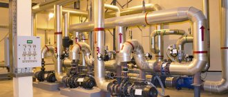
Fan at the entrance to the natural ventilation channel
Continued: to next page 2
Read page: Page 1, Page 2
More articles on this topic
- Insulation of house walls with external facade plaster
- Painting the facade and exterior walls of the house
- Cement, sand, crushed stone - selection and consumption of materials per 1 cubic meter of concrete
- Exterior decoration of house walls made of aerated concrete and gas silicate blocks
- Heating costs and heat transfer resistance in a private house
- DIY monolithic concrete staircase in a private house
- Finishing, covering the walls of the house with vinyl siding
- Setting up gas boiler power adjustment
An example of calculating the natural ventilation of a private house
For example, let's calculate natural ventilation in a one-story house with a total floor area of 120 m2. The house has five living rooms with a total area of 90 m2, a kitchen, a bathroom and toilet, as well as a dressing room (storage area) with an area of 4.5 m2. The height of the premises is 3 m. The house has ground floors on wooden joists with natural ventilation of the underground space through a ventilation duct. The height of the ventilated space under the floor is 0.3 m. We use concrete blocks to install ventilation channels - see above.
1.
In a private house, the air exchange standard for living rooms where air comes from the street is determined based on at least a single exchange of air volume per hour (air exchange rate = 1
1/hour
).
Then, the air flow from the street
for ventilation of five rooms: Qp = 90
m2
x 3
m
x 1
1/hour
= 270
m3/hour
;
2.
Air exchange standards for ventilation of rooms and spaces with exhaust ducts: kitchen 60
m3/hour
, bathroom and toilet 25
m3/hour
in each room;
The air exchange rate in the dressing room and the space under the floor on the joists is 0.2 1/hour
.
Then, to ventilate these rooms, it is necessary to remove to the street:
Qв1 = 60
m3/hour
+ 25
m3/hour
+ 25
m3/hour
= 110
m3/hour -
from the kitchen, bathroom and toilet;
Qв2 = 4.5 m2
x 3
m
x 0.2
1/hour
= 2.7
m3/hour
- from the dressing room;
Qв3 = 120 m2
x 0.3
m
x 0.2
1/hour
= 7.2
m3/hour
- from the space under the floor on the joists;
Total: Qв = 110 m3/hour
+ 2.7
m3/hour
+ 7.2 m3/hour = 119.9
m3/hour
3.
Let's compare: Qп > Qв.
We accept the minimum calculated total productivity of all exhaust ducts on the floor: Qр = Qп = 270 m3/hour
4.
For a one-story house, the height of the exhaust ventilation duct, taking into account the height of the attic, is assumed to be 4
m
.
5.
According to the table, for a room air temperature of 20 °C and a channel height of 4
m
, we find: the productivity of one standard ventilation channel with an area of 204
cm2
is equal to 45.96
m3/hour
.
(or 204: 45.96 = 4.44 cm2
- the channel cross-section required to pass 1
m3/hour
of air.) Then, the total minimum number of standard ventilation channels made of concrete blocks in the house is: 270
m3/hour
: 45.96
m3 /hour
= 5.87.
A minimum of 6 exhaust ducts
is necessary to ensure the minimum performance of natural ventilation in the house.
6.
There are four rooms in the house that need to be equipped with exhaust ventilation ducts - a kitchen, a bathroom, a toilet and a dressing room.
In addition, for design reasons, two ducts are required to ventilate the space under the floor. Total - 6 channels. A minimum of 6 exhaust ducts
are required to be installed on a floor in the house, based on the number of rooms and spaces where the installation of a ventilation duct is necessary.
7.
In addition, one more condition must be met - to ensure air exchange according to the standard in certain rooms - in the kitchen at least 60
m3/hour
, in the bathroom and toilet 25
m3/hour,
in the dressing room 2.7
m3/hour,
in the space under the floor 7.2
m3/hour
.
To fulfill this condition in the kitchen, one channel of the cross-section we have chosen is not enough. In order to use standard elements for laying channels, we decide to place a block of two standard ventilation channels
(2x204
cm2
) in the kitchen.
In the bathroom, toilet and dressing room we make one standard natural exhaust ventilation channel with a cross-section of 204 cm2
each.
To ventilate the space under the floor, we install two channels of 204 cm2 each. Thus, in total, to ensure minimum ventilation performance in each room with an exhaust ventilation duct, the house needs 7 natural ventilation channels
.
As a result, we finally accept 7 channels for construction and check that the ventilation performance meets the design standards:
— in the kitchen there is a block of two ventilation channels (2x204
cm2
) with a total capacity of 45.96
m3/hour
x 2 = 92
m3/hour
.
which is more than the standard for a kitchen of 60 m3/hour
;
— in the bathroom and toilet we install a block of two ventilation channels (2x204 cm2
) with a capacity of one channel of 45.96
m3/hour
, which is more than the standard of 25
m3/hour
;
— in the dressing room we install a single-channel ventilation unit (1x204 cm2) with a capacity of 45.96 m3/hour
, which is more than the standard calculation of 2.7
m3/hour
.
— to ventilate the space under the floor, we make two channels with a total capacity of 45.96 m3/hour
x 2 = 92
m3/hour
, which is more than the calculated standard of 7.2
m3/hour
.
— the total productivity of all seven ventilation channels on the floor is 92 m3/hour
+ 45.96
m3/hour
+ 45.96
m3/hour
+ 45.96
m3/hour
+ 92
m3/hour
= 322
m3/hour
, which exceeds the calculated standard productivity ventilation on the floor is 270
m3/hour
.
From the calculation results it is clear that the minimum required ventilation capacity of rooms with supply valves is provided with a small margin (322 m3/hour
> 270
m3/hour
). At the same time, the ventilation performance in some rooms with an exhaust duct exceeds the standard tens of times.
Exhaust ducts in the kitchen, bathroom, toilet and dressing room, as well as spaces under the floor, participate in the ventilation of other rooms in the house.
Therefore, the performance of exhaust ducts in these rooms is adjusted taking this circumstance into account. Do not reduce ventilation performance in these rooms, for example, by installing small ventilation grilles at the entrance to the duct.
It should be noted that the operation of the fan in the hood above the kitchen stove or in the bathroom should not be taken into account when calculating the air exchange of natural ventilation in these rooms.
The above method for calculating ventilation channels is simplified and not professional. It is better to entrust the design of natural ventilation in the house to specialists.
Ventilation duct above the roof
When there is wind, in air flows flowing around the roof and other obstacles, zones of rarefaction and zones of high pressure are formed, like near an airplane wing. The location of such zones constantly changes depending on the strength and direction of the wind.
If the head of the ventilation duct falls into an area of vacuum, then the draft in the duct increases; if it enters a pressure zone, then the draft in the duct decreases or even overturns, the air begins to move in the opposite direction from the street into the house. It can be especially unpleasant when, in winter, cold air suddenly begins to blow from the ventilation grill into the room.
To reduce the influence of wind on the operation of natural ventilation, the head of the ventilation duct above the roof must be placed at a certain distance.
| Minimum distances of the head of the natural ventilation channel from the house structures. a - on a flat roof with a slope of less than 12 degrees; b - on a pitched roof with the head located closer than 1 m from the ridge; c - the same, but with the head located further than 1 m from the roof ridge; d - location of the head near vertical surfaces (wind barriers). |
Calculation of a duct heater
electric duct heater
The calculation of an electric ventilation heater is carried out as follows:
P = v * 0.36 * ∆ T
here v is the volume of air passed through the heater in cubic meters per hour, ∆T is the difference between the air temperature outside and inside, which must be provided to the heater.
This indicator varies between 10 – 20, the exact figure is set by the client.
Calculation of a heater for ventilation begins with calculating the frontal cross-sectional area:
Af= R * p 3600 * Vp ,
here R is the volume of inlet flow, cubic m.h, p is the density of atmospheric air, kgcub.m, Vp is the mass air velocity in the area.
The cross-sectional size is necessary to determine the dimensions of the ventilation heater. If, according to calculations, the cross-sectional area turns out to be too large, it is necessary to consider the option of a cascade of heat exchangers with a total calculated area.
The mass velocity indicator is determined through the frontal area of the heat exchangers:
Vp = R * p 3600 * A f.fact
To further calculate the ventilation heater, we determine the amount of heat required to warm the air flow:
Q =0.278 * W * c ( T p - T y),
here W is the flow of warm air, kg/hour, Тп is the temperature of the supply air, degrees Celsius, Тu is the temperature of the street air, degrees Celsius, c is the specific heat capacity of the air, a constant value of 1.005.
Since fans in supply systems are placed in front of the heat exchanger, we calculate the flow of warm air as follows:
W = R*p
When calculating the ventilation heater, you should determine the heating surface:
Apn=1.2 Q k ( T s.t - T s.v),
here k is the heat transfer coefficient of the heater, Tс.т is the average temperature of the coolant, in degrees Celsius, Tс.в is the average inlet temperature, 1.2 is the cooling coefficient.