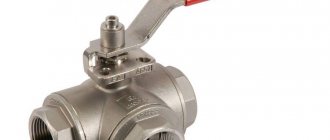
Danfoss ASV-PV, DN15, article number - 003Z5501.
A differential pressure regulator is a special fitting used in piping systems. With this device, the pressure difference of the liquid medium is automatically maintained at the level of preset values. The regulation of differences is carried out by a valve, the flow area of which changes based on pressure parameters.
Types of water pressure regulators
There are five types of water pressure regulators:
- Flow-through:
- Membrane;
- Piston;
- Automatic;
- Electronic.
Based on the principle of installation and use, there are two types of regulators:
- Up to yourself;
- After myself.
The regulator “before itself” equalizes the pressure in the system located in front of it. Such regulators are used where it is necessary to protect the pipeline and plumbing fixtures from water hammer and high pressure. For example, in heating and cooling systems.
The water pressure regulator “after itself” equalizes the water pressure at the outlet. Such regulators are used where water is supplied to the end consumer:
- In the water supply system in the apartment;
- Irrigation systems;
- Wells, pumps, pump rooms;
- Water supply for technical needs.
As for the materials from which water pressure regulators are made, they can be:
- Cast iron;
- Steel;
- Brass;
- Titanium.
They also differ in configuration. Options may include:
- Pressure gauge;
- Mechanical cleaning filter;
- Ball Valves;
- Spare set of gaskets;
- Air vent.
What does adjusting radiators give?
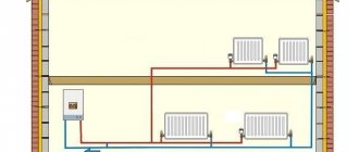
The ability to adjust the temperature of heating radiators to suit your needs provides several advantages:
- Create a comfortable temperature in the room for its residents. There is no need to constantly open windows, create drafts and spend money on heating the street.
- Savings on heating are significant and can range from 25 to 50%. However, before adjusting the temperature of the radiator in the apartment, it is recommended to take a number of energy-saving measures. Install plastic windows, insulate interpanel seams, and insulate the walls. All these measures must be carried out before the start of the heating season, so as not to carry out work in emergency mode.
- Airing in the pipes is eliminated, the coolant moves freely inside and effectively transfers heat to the room.
- The ability to distribute heat evenly in all rooms.
- If necessary, you can maintain different temperature conditions in different rooms. Let’s say that in one you set the temperature to 25 ℃, and in the other it is enough to maintain 17 ℃.
Comfortable room temperature is the main advantage
It is obvious here that if it is possible to adjust the temperature of the radiators, then you should definitely take advantage of it. We hope that our article will help you do it right.
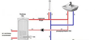
The principle of operation of a membrane water pressure regulator after itself
This pressure regulator consists of the following parts (see figure):
- A – Valve inlet;
- B – Valve output;
- C – Connection to the membrane chamber;
- D – Membrane chamber;
- E – Spring;
- F – Locking disc.
“Afterwards” water pressure regulator device.
It works like this:
- When the water pressure after the locking disc increases, it fills the membrane chamber;
- As the membrane chamber fills, the membrane presses on the rod connected to the locking disc;
- The disc closes the hole in the valve and the pressure after the valve decreases.
As the pressure decreases, the following happens:
- Water from the membrane chamber returns to the valve through the pipe;
- The pressure in the chamber decreases, the spring pulls back the locking disc;
- The flow of water through the hole in the valve increases and the pressure rises.
The principle of operation of the water pressure regulator after itself.
How does a membrane water pressure regulator work?
The design of a water pressure regulator upstream is more complex than one that operates on the downstream principle. It consists of (see figure):
- A – Valve inlet;
- B – Valve output;
- C – Branch pipe from the valve inlet to the pilot regulator;
- D – Branch pipe from the membrane chamber to the valve outlet;
- E – Pilot regulator;
- F – Membrane chamber;
- G – Locking disc.
The water pressure regulator device is up to you.
The principle of operation of the water pressure regulator can be divided into two stages: increasing the pressure and decreasing it. When the valve inlet pressure increases, the following occurs:
- Water flows through the pipe from the inlet to the valve into the pilot regulator, where it presses on the spring;
- The pilot regulator opens the hole between the membrane chamber and the pipe to the outlet of the valve;
- Water leaves the membrane chamber, the spring pulls back the locking disc;
- The pressure at the valve inlet decreases.
When the pressure at the valve inlet decreases, the following occurs:
- Water from the pilot regulator is returned through the pipe to the valve inlet;
- The pilot regulator spring expands and the hole between the membrane chamber and the pipe to the valve inlet opens;
- The membrane chamber is filled with water and the locking disc closes the hole;
- The pressure at the valve inlet increases.
The principle of operation of the water pressure reducer.
Piston water regulator: operating principle
In a piston regulator, the balance of incoming and outgoing pressure is achieved by a spring pushing the piston (see figure below). It works like this:
Water enters the first chamber, from which it passes into the second through an opening. When the pressure in the second chamber increases, it pushes the piston, which compresses the spring. The locking disc closes the passage hole and the pressure in the second chamber decreases.
When the water pressure decreases, the pressure in the first chamber decreases. The spring pushes out the piston and locking disc. Through the passage hole, water enters the second chamber and the pressure increases.
The device of a piston water pressure regulator.
The flow force can be adjusted by moving the spring and piston through the second chamber. For this purpose, such devices have an adjusting screw. By tightening it, you reduce the outlet pressure, and by unscrewing it, you increase it.
How does an automatic pressure regulator work?
In its operating principle, an automatic regulator is similar to a piston regulator. The only difference is that the membrane acts as a piston (see figure), and the damper is spring-loaded.
Automatic membrane pressure regulator device.
When the pressure of incoming water increases, it pushes the membrane upward. It pulls the flap and the hole is partially blocked. In this case, the pressure of the outlet flow decreases.
As the pressure of the incoming flow decreases, the membrane moves down, lowering the damper. The duct opening opens more and the outlet pressure increases.
A distinctive feature of automatic diaphragm valves is the presence of a second spring on the damper. It allows you to more accurately regulate pressure. The required outlet pressure is adjusted using the adjusting screw.
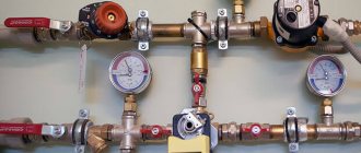
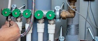
Installation and configuration
Installing a household regulator is as easy as a water meter. Especially if you do this right away when installing the internal wiring. If it needs to be integrated into an already operating system, then to do this you first need to turn off the water and drain its remains by opening all the taps in the house. Then cut out part of the pipe, install connecting fittings and connect the gearbox to them, sealing all connections. In this case, it is necessary to take into account the direction of flow indicated by the arrow on the body, and place the pressure gauge vertically.
Electronic regulators
At the moment, these are the most advanced and accurate devices. They can work in modes before and after themselves. Their operating principle is as follows:
- A sensor at the inlet and outlet determines the water pressure;
- Signals from the sensors enter the control device;
- The device activates the locking mechanism or regulates the operation of the circulation pump.
Electronic water pressure regulators allow you to set the settings as accurately as possible. Due to this, they are used in systems designed for specific needs. But their cost is also high.
Electronic water pressure regulator.
Application area
Modern differential pressure regulators are most often used in water heating systems with hydraulic mode. The presence of such a device allows you to achieve the most stable pressure in the pipes involved in the operation of the heating network. If the device is installed correctly, the heating equipment will be reliably protected from zero flow associated with a system restart.
Danfoss ASV-PV, DN15.
Automatic regulators require virtually no maintenance. With relatively simple manipulations associated with setting up devices, they are able to maintain the specified parameters with fairly high accuracy.
Choose wisely
When choosing a water pressure regulator, you need to pay attention to the following:
- Maximum operating pressure of the device (it should be 20-30% higher than the maximum in the system);
- The diameter of the inlet and outlet must exactly match the diameter of the system pipes;
- The larger the pressure adjustment range, the better, but it is worth taking into account the features of the heating or water supply system;
- Before you settle on a type of regulator, make sure it will suit your needs. The option that is suitable for a water supply system cannot always be used in a heating system;
- When choosing an electronic regulator to connect to the circulation pump, check their compatibility.
Characteristics
- The nominal diameter, which must be selected according to the nominal diameter of the heating pipes. Regulated by GOST 28338-89.
- Nominal pressure ensuring the service life declared by the manufacturer. The parameter is regulated by GOST 26349-84.
- Maximum capacity (m3/h) at which the reducer regulates pressure within specified limits.
- Operating temperature range and adjustable coolant pressure.
Correct selection of the gearbox and its professional installation ensure protection of the heating system from failures, and heating devices from breakdowns and incorrect operation.
Correct installation of the water pressure regulator
Installing the pressure regulator is easy. When installing it or inserting it into the system, everything is done in the same way as when installing any plumbing fixture or shut-off valve. But there are certain rules that you should know.
In the apartment
Installing a water pressure regulator in an apartment requires compliance with the following rules:
- The regulator must be installed at the entrance to the heating system and regulate the pressure “after itself”;
- Before and after the regulator, it is necessary to install (if they are not present) ball valves in case of need for dismantling;
- Be sure to install a coarse filter in front of the regulator;
- If a conventional or automatic air vent is installed, the regulator must be located after it.
- Strictly observe the direction of water flow;
- Do not install the water pressure regulator “upside down”;
- The closer the regulator is to the riser, the better.
In a private house
When installing a pressure regulator in a private home, consider the following:
- You should be able to dismantle the regulator - install ball valves in front of it and after it;
- The pressure regulator “before itself” is installed in front of the pump, “after itself” - behind the pump;
- If the system does not have a coarse filter, install it in front of the regulator and circulation pump;
- If it is not water that circulates in the system, but a coolant, make sure that it will not damage the mechanisms and gaskets of the device, read the specification for the coolant;
- Observe the direction of flow when installing the regulator;
- Do not install the device upside down.
Main menu
Hello, friends! This article was written by me in collaboration with Alexander Fokin, head of the marketing department of Teplokontrol OJSC, Safonovo, Smolensk region. Alexander is very familiar with the design and operation of pressure regulators in the heating system.
In one of the most common schemes for heating points in a building - dependent, with elevator mixing, direct-acting pressure regulators RD "after themselves" serve to create the necessary pressure in front of the elevator. Let's take a little look at what a direct-acting pressure regulator is. First of all, it must be said that direct-acting pressure regulators do not require additional energy sources, and this is their undoubted advantage and advantage.
The principle of operation of the pressure regulator is to balance the pressure of the setting spring and the pressure of the coolant supplied through the membrane (soft diaphragm). The membrane perceives pressure pulses on both sides and compares their difference with a given one, set by appropriate compression of the spring with the adjustment nut.
Each number of revolutions corresponds to an automatically maintained pressure difference. A distinctive feature of the membrane in the pressure regulator after itself is that on both sides of the membrane there are not two coolant pressure pulses, as with a differential pressure (flow) regulator, but one, and on the second side of the membrane there is atmospheric pressure.
The pressure pulse of the RD “after itself” is selected at the outlet of the valve in the direction of movement of the coolant, maintaining the specified pressure constant at the point of sampling this impulse.
When the pressure at the inlet to the RD increases, it closes, protecting the system from excess pressure. The RD is set to the required pressure using the adjustment nut.
Let's consider a specific case. At the entrance to the ITP, the pressure is 8 kgf/cm2, the temperature curve is 150/70 °C, and we previously made a calculation of the elevator and calculated the minimum required available pressure in front of the elevator, this figure turned out to be 2 kgf/cm2. Available pressure is the pressure difference between the supply and return in front of the elevator.
For a temperature curve of 150/70 °C, the minimum required available pressure, as a rule, the calculation results in 1.8-2.4 kgf/cm2, and for a temperature curve of 130/70 °C, the minimum required available pressure is usually 1.4- 1.7 kgf/cm2. Let me remind you that we got a figure of 2 kgf/cm2, and a graph of 150/70 °C. Return pressure is 4 kgf/cm2.
Therefore, in order to achieve the required available pressure calculated by us, the pressure in front of the elevator must be 6 kgf/cm2. And at the entrance to the heating point, let me remind you, the pressure is 8 kgf/cm2. This means that our RD must work in such a way as to relieve the pressure from 8 to 6 kgf/cm2, and keep it constant “after itself” equal to 6 kgf/cm2.
We come to the main topic of the article - how to choose a pressure regulator for this particular case. Let me explain right away: the pressure regulator is selected based on its throughput. Capacity is designated as Kv, less commonly the designation KN is used. Capacity Kv is calculated by the formula: Kv = G/√∆P. Throughput can be understood as the ability of the RD to pass the required amount of coolant in the presence of the required constant pressure drop.
In the technical literature, the concept Kvs is also found - this is the valve capacity in the maximum open position. In practice, I have often observed and observed that RDs are selected and then purchased according to the diameter of the pipeline. This is not entirely true.
We proceed with our calculation. The flow rate G, m3/hour is easy to obtain. It is calculated from the formula G = Q/((t1-t2)*0.001). We have the required number Q in the heat supply contract. Let's take Q = 0.98 Gcal/hour. The temperature graph is 150/70 C, therefore t = 150, t2 = 70 ° C. As a result of the calculation, we get a figure of 12.25 m3/hour. Now it is necessary to determine the pressure difference ∆P. What does this number mean in general? This is the difference between the pressure at the inlet to the heating point (in our case 8 kgf/cm2) and the required pressure after the regulator (in our case 6 kgf/cm2).
We make a calculation. Kv = 12.25/√(8-6) = 8.67 m3/hour. In technical and methodological manuals it is recommended to multiply this figure by another 1.2. After multiplying by 1.2 we get 10.404 m3/hour.
So, we have the valve capacity. What needs to be done next? Next, you need to decide which company’s RD you will purchase and look at the technical data. Let's say you decide to purchase RD-NO from the company Teplokontrol OJSC. We go to the company’s website https://www.tcontrol.ru/, find the required RD-NO regulator, and look at its technical characteristics.
We see that for a diameter dу 32 mm the throughput is 10 m3/hour, and for a diameter dу 40 mm the throughput is 16 m3/hour. In our case, Kv = 10.404, and therefore, since it is recommended to choose the nearest larger diameter, we choose dу 40 mm. At this point, we consider the calculation and selection of the pressure regulator complete.
Next, I asked Alexander Fokin to talk about the technical characteristics of pressure regulators RD NO JSC Teplokontrol in the heating system.
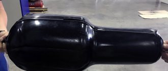
Regarding the RD-NO of our production. Indeed, there used to be a problem with membranes: the quality of Russian rubber left much to be desired. But for 2 and a half years now we have been making membranes from material from EFBE (France), a world leader in the production of rubber-woven membrane fabrics. As soon as the membrane material was replaced, complaints about their rupture virtually stopped.
At the same time, I would like to note one of the design nuances of the membrane unit in RD-NO. Unlike Russian and imported analogues on the market, the membrane of RD-NO is not molded, but flat, which allows it to be replaced if it breaks with any piece of rubber of similar elasticity (from a car inner tube, conveyor belt, etc.).
As a rule, it is necessary to order the “native” membrane from pressure regulators from other manufacturers. Although it’s fair to say that membrane rupture, especially when working on water with temperatures up to 130˚C, is, as a rule, a disease of domestic regulators. Foreign manufacturers initially use highly reliable materials in the manufacture of the membrane.
Oil seals.
Initially, the RD-NO design had an oil seal, which consisted of spring-loaded fluoroplastic cuffs (3-4 pieces). Despite the simplicity and reliability of the design, they had to be tightened periodically with the gland nut to prevent leakage of the medium.
In general, based on experience, any stuffing box seal has a tendency to lose its tightness: fluorine rubber (EPDM), fluoroplastic, polytetrafluoroethylene (PTFE), thermally expanded graphite - due to mechanical particles getting into the stuffing box area, from “clumsy assembly”, insufficient cleanliness of the rod processing , thermal expansion of parts, etc. Everything leaks: Danfoss (no matter what they say), and Samson with LDM (although this is an exception here), I’m generally silent about domestic control valves. The only question is when it will leak: during the first months of operation or in the future.
Therefore, we made the strategic decision to abandon the traditional gland seal and replace it with a bellows seal. Those. use the so-called “bellows seal”, which provides absolute tightness of the stuffing box assembly. Those. The tightness of the stuffing box assembly now does not depend on temperature changes, or on the ingress of mechanical particles into the rod area, etc. — it depends solely on the service life and cyclic resistance of the bellows used. Additionally, in case of failure of the bellows, a backup sealing ring made of fluoroplastic is provided.
We first applied this solution to RDPD pressure regulators, and at the end of 2013 we began producing the modernized RD-NO. At the same time, we were able to fit the bellows into existing housings. Usually the biggest (and in fact the only disadvantage) of bellows valves is their increased overall dimensions.
Although, we believe that the bellows used are not fully suitable for solving these problems: we think that their resource will not be enough for the entire required 10 years of operation of the regulator (which are indicated in GOST). Therefore, now we are trying to replace the used tubular bellows with new membrane ones (few people use them yet), which have several times longer service life, smaller dimensions with greater “elasticity,” etc. But so far, in the year of production of bellows RD-NO and in 4 years of production of RDPD, there has not been a single complaint about bellows rupture or media leakage.
I would also like to note the unloaded cellular design of the RD-NO valve. Thanks to this design, it has an almost perfect linear characteristic. And also the impossibility of valve distortion as a result of any rubbish floating in the pipes.