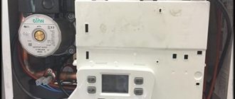
All gas boilers are equipped with an internal sensor. It, in turn, maintains a certain temperature in the supply pipeline. But you have to choose the desired temperature regime yourself. To do this, you need to regulate the power of the equipment. To avoid visiting the furnace room every time the weather conditions change, you can install a room thermostat in the house. Let us consider in detail what types of room thermostats there are, as well as how to connect them correctly.
Why do you need a room thermostat?
Not everyone wants to constantly go down to the furnace room and regulate the temperature. Therefore, it would be wise to purchase a room thermostat. This way, you can directly regulate the power of the heating boiler based on the air temperature in the house. The operating principle of a room thermostat is as follows: after the device reaches the set temperature in the room, the device closes an electrical circuit that connects it to the boiler. A heat-sensitive element located inside the housing is responsible for this action. This element mechanically acts on electrical contacts. In products with a more complex device, such an element is a temperature sensor.
After the circuit is closed, the controller or gas valve turns off the operation of the burner or reduces the flame. It all depends on the design of the device. The coolant in the radiators will cool down, and the air temperature in the room will decrease. As a result, the circuit breaks and the burner operation resumes.
Such regulation is effective. Since fuel is used as much as needed.
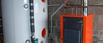
Boiler operation control
Thermostat for incubator
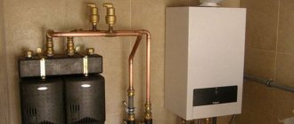
A gas boiler or electric boiler can be controlled by a thermostat installed in the living room, as well as by a more complex background temperature controller - a programmer. Depending on the design of the boiler, there are three options for connecting such control devices:
- To special connectors on the boiler control board (for wall-mounted, volatile models);
- In series with the boiler thermostat with a mandatory connection to the gas valve (for non-volatile floor-standing models);
- Instead of a boiler thermostat (for floor-standing boilers).
Modern wired programmer for a gas boiler
Important! To install such regulators, select the rooms most distant from the boiler and those most visited by residents: bedroom, living room.
Types of thermostats
Room thermostats can be divided by device, by method of device and by functionality.
Based on their technical design, room thermostats can be divided into 3 types:
- Electromechanical.
- Electronic.
- Mechanical.
According to the method of installation, room thermostats are divided into two types:
Based on functionality, the following types of room thermostats can be distinguished:
- Programmable thermostats. They can set the desired regime for several days in advance.
- Simple thermostats. They only maintain the required temperature.
- Room thermostats cannot create a harmful electromagnetic field. They only transmit a small impulse.
Advantages of using a thermostat
The main advantages of temperature controllers are:
- The ability to maintain a comfortable temperature background in the living room;
- Saving energy resources used for various types of heating equipment: gas or electricity;
- Increasing the service life of heating equipment - the use of a thermostat significantly reduces the turn-on and operation time of the boiler, which extends its service life;
- Low cost and high payback;
- Easy to install and use.
Thus, room temperature controllers are very simple, convenient and reliable devices. Maintaining a comfortable temperature background in residential premises, they not only allow you to significantly save gas and electricity, but also increase the service life of expensive boilers and other heating equipment.
Device and connection
It is best to install room thermostats in living rooms. If you install a thermostat in the kitchen or hallway, false alarms may occur. It is better to install in a room where the temperature is lowest or in a room where there are the most people.
But you cannot install a room thermostat next to a radiator or heater. Also, the sun's rays should not hit the device. They also recommend not installing thermostats near electrical appliances that may emit thermal noise, and you should also avoid installing the thermostat in a draft.
You can turn the boiler on and off using a special relay. The thermostat can be connected via a cable or using a terminal on the boiler. The programmer requires batteries to operate. The technical data sheet of the device indicates the rules for connecting the thermostat. You must carefully study the instructions.
Optimal temperature in the house or how to install a thermostat in a distant room without wires
It is no secret to many that devices such as weekly thermostats help ensure optimal room temperature in the house, and also save energy resources spent on heating. For the device to operate correctly, it is usually placed in the farthest room, where the temperature is lowest. But most thermostats require a wired connection to the boiler for control, and it is not always possible to lay these wires. The solution to such a problem will be discussed in this article. For anyone who is interested, please see below... I had to face a similar problem. The structure of my house is quite elongated, and in order to install the thermostat correctly, I needed to stretch more than 50 m of cable through the rooms with renovations already done; the alternative was laying it along the facade, but I immediately discarded it. Moreover, running a cable from the street to the boiler was also problematic, and I didn’t want to spoil the appearance of the facade with another wire, there’s already enough extra. The boiler itself is installed in the kitchen and placing the thermostat nearby was a really bad idea. As a result, I came to the idea that the thermostat still needed to be moved to the back room, and the signal should be transmitted over a radio channel. The process of developing my next craft began, as usual, with setting a problem. So let's get started...
TK
Let's determine the requirements for the device to solve the problem.
- The design of the devices should be small-sized and housed in an aesthetically pleasing white or black housing.
- The receiver and transmitter module must be powered by a pair of AA batteries.
- The operating life of the modules from one set of batteries must be at least one year.
- Connection to the thermostat and gas boiler must be carried out using standard interfaces without making any changes to the design.
- Devices must be assembled using available components from local suppliers.
Hardware
Once we have decided on the basic requirements, we move on to design. Let's start with the hardware. Based on the technical specifications, the main requirements for the element base will be: the ability to operate in the voltage range from 1.8 to 3 volts. And also the ability to switch to sleep mode or turn off peripherals at times when they are not needed. I decided to start my selection path with selecting a transceiver. I considered the simplest solutions in the form of MX-FS-03V and MX-05V modules, the price is of course very attractive, but the quality of work according to reviews is terrible, and the communication range is not so great. And in my case it was necessary to transmit the signal through 4 walls. In addition, I initially intended to make a confirmation of shipment, so the communication needed to be two-way, which would require two sets. LoRa modules and various HC series modules were also reviewed. The assortment was still limited to what was sold locally. As a result, having considered all the available options, I decided to opt for ready-made SI4432 modules. In terms of price-performance ratio, in my opinion, they were the best. This module has extensive technical capabilities and is also very economical with the correct settings. The ability to control the power of the output signal is also very useful, because you can choose the optimal one, thereby reducing energy consumption from batteries. Here is a table with characteristics from the documentation.
Let's take a closer look at the energy consumption indicators in various modes from the table. We will later need this data to calculate the battery life of devices.
In our case, using the Sleep mode is already acceptable, not to mention completely disabling it with the Shutdown function. I initially intended to use ATMega 8 as the central processor, but after studying the documentation in more detail, I realized that it does not fall within my supply voltage range. As a result, I chose the ATMega 328P, because... it fully met all my requirements. Looking ahead, I will say that the fact that I found a ready-made bootloader for it also played in its favor, but more on that later. Let's take a closer look at the selected controller in terms of power consumption and core clocking. Let's first deal with clocking. Because Since our operating voltage range is up to 3 volts, our choice of quartz resonator is also limited, and the following graph tells us this
As we can see, we cannot get stable operation at 8 MHz, therefore, we will use quartz at 4 MHz. Now let's look at power consumption in various operating modes. Here is a table from the documentation describing the energy consumption characteristics.
Thus, if you switch the controller to Power-Down mode, the consumption of the microcontroller itself is reduced to 44 uA, with certain reservations of course. In addition to the already selected elements, we will add a red indicator LED with an operating current of 1 mA. This is where the common components for the receiver and transmitter end. Let's look at additional components for the receiver. At the output of a conventional room thermostat there is a relay contact with good switching ability (250 V 5 A), so it doesn’t matter what it controls, therefore, according to the terms of the technical specifications, our receiver must have the same relay output. But how to ensure low power consumption of the relay in the on mode, because the coil of even the smallest relay consumes tens of milliamps, and the factory thermostat from one set of normal batteries works, without exaggeration, for at least 2 heating seasons. I thought about this problem for a couple of days and suddenly, while repairing one of the devices, it dawned on me that there was simply a bistable relay there. And why during repairs, because they are used in the device being repaired. This type of relay is capable of maintaining its state indefinitely without consuming energy. In order for the relay to change its state, it is enough to apply a pulse to the required coil, in the case of a two-winding relay, or a pulse in reverse polarity, in the case of a relay with one winding. Thus, we have decided on the type of relay, but what to do with a specific model? After a little searching on the Internet, I came to the conclusion that getting a low voltage relay would be a problem for me, so I had to settle on the 24 V relays I had from Takamisawa ALD24W-K. But this solution gave rise to a new problem - where to get 24 V? The answer was found quickly, perhaps it is not the most correct, but still. I decided to install a boost converter and raise the voltage to 20 V, which is quite enough to reliably switch the relay. The converter was taken from a fairly common module based on MT3608. This is a working solution that I have tested more than once, including the design of an electric screwdriver (you can read about it here on Habré). The EN output allows you to control the operation of the converter, which significantly reduces power consumption. Actually, here is the data from the documentation.
Having collected all the information received together, I drew diagrams of both devices: Transmitter
Receiver
Having finished with the hardware part of the project, we will move on to the algorithms and their software implementation.
Algorithm
Let's start by developing a general operating concept and algorithm for our devices. The figure below shows a general sequence diagram for all devices involved in the process.
As you can see, the algorithm is not complicated, I will give it a narrative presentation (well, I’m too lazy to draw a flowchart, forgive me).
Let's start with the transmitter, because... it is the simplest from an algorithmic point of view. The transmitter microcontroller performs the following sequence: - checks the state of charge of the batteries; if the charge is low, we indicate the discharge with the built-in LED. — polls the input status. — transmits this state via a radio channel. — switches the transmitter to sleep mode and falls asleep for 1 minute. — the cycle repeats from the beginning. With the receiver everything is a little more complicated. The microcontroller operates according to the following algorithm: - checks the charge status of the batteries; if the charge is low, we indicate the discharge with the built-in LED. — we wait for a packet from the transmitter, if a signal is not received within 2 minutes, we fall asleep for 59 seconds, after which the cycle begins from the beginning. - if the packet has arrived, we get a new relay state. - if the new state of the relay differs from the previously saved one, then turn on the boost converter and switch the relay to the desired state. - fall asleep for 59 seconds - repeat the cycle from the beginning. Thus, when turned on for the first time, the receiver waits for a signal from the transmitter, as soon as it receives it, it makes a change in the state of the relay and falls asleep 1 second less than the transmitter. As a result, by the time a new parcel is sent, the receiver is already in service and is waiting for a new parcel, i.e. It's like it's synchronized by the transmitter. As a result, we managed to save a lot of energy consumption. If a signal is not received from the transmitter, then we wait a maximum of 2 minutes, this interval was chosen to ensure that we can catch the signal regardless of the time the transmitter is turned on. But it is extremely uneconomical and is intended solely for synchronizing devices.
Lifetime
When the algorithm became clear, let's try to calculate the battery life. Let's turn a little to the theory necessary to obtain accurate numbers when calculating the operating time of sensors from a set of batteries. So, first let's look at when and what electricity is spent on. Let's take a closer look at the sending procedure. To transmit the relay state, we need to generate a packet and send it over the air. In general, the structure of such a package looks like this:
I used the default transmitter settings, i.e. FSK, No Manchester, Rb = 2.4kbs, Fd = 36kHz. The volume of transmitted data in a packet is 3 bytes. The preamble size will be 40 bits based on the table:
In order not to delve into the jungle of module settings and library operation, we will accept the remaining parameters as the maximum allowable. As a result, we get a total packet size of 5 bytes + 4 bytes + 4 bytes + 1 byte + 3 bytes + 2 bytes = 19 bytes, i.e. 152 bits. That at a speed of 2400 bps the transfer time will be approximately 64 ms. Let's refer to the table of energy consumption of the module at the beginning of the article and take from there the current value when transmitting with an output power of 13 dBm. Thus, when sending data, the module consumes 30 mA. In receive mode, the module will statically consume 18.5 mA based on the same table. I was never able to switch the module to Shutdown mode; for some reason I could not bring it out of the coma, as a result I limited myself to the Sleep mode in which the module consumes 1 uA. Also, during the reception and transmission of the packet, I turn on the red LED connected through a 1 kOhm resistor to 3.3 volts, it consumes about 1 mA. The microcontroller consumes 2.4 mA in wake mode, and 44 uA in sleep mode with WDT enabled. The data is obtained from the above table. The receiver also has a parasitic current leak when the thermostat contact is closed through a pull-up resistor to ground (see transmitter diagram), so 3.3 V / 10 kOhm = 33 uA flows through it. This seemed like a big value to me, so in the circuit I changed the resistor value to 100 kOhm, but in the hardware it’s still assembled with 10 kOhm, so we’ll count it as it really is. The receiver has more additional consumers. First, it is a 20 volt boost converter. In sleep mode it consumes 1 uA. In operating mode at idle, the consumption will be 2.2 mA; in the program I wait 100 ms for the converter to start. We use a relay coil as a load, its characteristics are indicated below: Thus, it turns out that the coil, when powered by 20 volts, will consume 20 V / 1920 Ohm = 11 mA. Now let's turn to the graph of efficiency versus load current consumption to estimate the total consumption of the converter with the relay coil connected.
As we can see, with such consumption the graph does not reflect the efficiency, but let’s assume that it also moves linearly in the direction of decrease, and let us assume that in the worst case the efficiency will be approximately 85%.
As a result, the current consumption will be 11 mA / 0.85 = 13 mA. It is worth recognizing that in reality the peak current when starting the converter will be at least 1A, and the operation and startup processes are complex, and I am not the person who is able to present them correctly, so I will skip them and simplify the process a little. The pulse time generated to switch the relay is 20 ms. Now that we have figured out who consumes energy and how much, let’s calculate the theoretical lifespan of AA batteries. Again, consider the receiver and transmitter separately. Let's start, as always, with the transmitter. Let's take the algorithm given above as a basis. The controller's wake time will be slightly longer than the transmission time and, taking into account the costs of setting up the module, polling the input and measuring the battery voltage will be 70 ms, then the controller will be put into sleep mode for one minute. Thus, during one cycle of operation, the controller will consume 0.07 s * (30 mA transmitter + 1 mA LED + 2.4 mA MK) + 60 s * (44 uA MK + 1 uA transmitter + 33 uA input resistor) = 2.338 mA*s + 4.68 mA*s = 7.018 mA*s. Dividing the resulting value by 60.07 s we get the average current value for one second - 0.117 mA. The average capacity of one AA-size battery is 2800 mA*h (when connected in series, the total capacity of the batteries does not increase, in case anyone doesn’t know) - this is 2800 * 3600 = 10,080,000 mA*s. As a result, the theoretical operating time of the transmitter from one set of batteries is 10,080,000 mA*s / 0.117 mA / 3600 s / 24 hours = 997 days. Now about the receiver. Let's also take as a basis the operating algorithm given above, but with one caveat, we turned on both the receiver and the transmitter almost simultaneously, and, therefore, the receiver was immediately synchronized with the transmitter. For it, the maximum waking time of the controller will be the sum of the packet waiting time (it will also include receiving, since an interruption by the module will be generated only after the packet has been fully received), removing it from the module, starting the converter and setting a new relay state, as well as measuring battery voltage. Summing up all the data, we get - 1.126 s, then the controller will be put into sleep mode for 59 seconds. But because the operating cycle is more complex than in the receiver, then the calculation will consist of a larger number of states. For one cycle of operation, the controller will consume 1.006 s * (18.5 mA receiver + 2.4 mA MK) + 0.1 * (0.1 s * (18.5 mA receiver + 1 mA LED + 2.4 mA MK + 2.2 mA converter at XX) + 0.02 s * (18.5 mA receiver + 1 mA LED + 2.4 mA MK + 13 mA converter) ) + 59 s * (44 uA MK + 1 uA receiver + 1 uA converter) = 21.0254 mA + 0.1*(2.41 mA + 0.698 mA) + 2.714 mA = 24.0502 mA*s. The coefficient 0.1 reflects the fact that we switch the relay only in one out of 10 cycles. Dividing the resulting value by 60.126 s, we obtain the average current value for one second - 0.4 mA. Let's calculate the battery life. As a result, the theoretical operating time of the receiver from one set of batteries is 10,080,000 mA*s / 0.4 mA / 3600 s / 24 hours = 291 days, provided that we change the relay state every 10 minutes. Obviously, in these calculations, all times of more than two years are not realized due to the chemical features of the batteries. AA batteries are not capable of operating for more than two years when the device is constantly powered with even a negligible current, despite the fact that the capacity should be sufficient. But anything less than two years old will become a capacity limitation. Unfortunately, the calculation results for the operating life of the receiver do not fully fit into the technical specifications, but in this situation I made myself a concession.
Implementation in code
To be honest, I am skeptical about Arduino and similar IDEs. I started to understand programming microcontrollers in C and working with registers was more understandable and predictable to me than veiled calls to high-level functions. Although in general I have studied the platform itself and I still do some small projects in it. This time too, laziness got the better of me. I was attracted by the presence of a ready-made library for SI4432 modules for Arduino and didn’t really want to waste time trying to port it to CVAVR. And the rest of the code is extremely simple. After spending several evenings studying libraries for working with the module, as well as the sleep mode of the microcontroller, the first versions of the receiver and transmitter sketches were ready quite quickly. Next, it was necessary to assemble the hardware and continue development with real hardware.
It's alive…
A project with a diagram and printed circuit boards was developed in the EasyEDA online service. I didn’t bother with double-sided boards, so I installed jumpers on the reverse side. Here is a photo of the finished transmitter boards...
... and the receiver.
I bought holders for the batteries and also bought cases. Honestly, I wanted white, but we didn’t have any in stock, so we had to assemble them in black. I first assembled the boards without modules, because... You need to first fill the controller with the bootloader using the programmer. And since the module is 3.3 volts, and the programmer is 5 volts and they use the same bus, it is better to solder the module after flashing it. I checked the power supply and programmed the bootloader. Since there is no solder mask on the board, I glued a piece of Kapton under the modules. I soldered the modules and started debugging the firmware. I immediately stepped on a rake in the form of module freezes, everything turned out to be tritely simple, the 3-volt stabilizer that I used did not supply the required current, after connecting the LBP to the receiver and batteries to the transmitter, everything worked stably. In addition, I also installed an electrolytic capacitor close to the converter on the power circuit for its normal startup. All I had to do was add the remaining logic described above. With standard antennas the connection was very stable. Structurally, the receiver and transmitter fit completely into the purchased housings. The boards were secured to standard racks using self-tapping screws to the bottom of the case, and I attached the battery holders with double-sided tape to the top. The case closes quite tightly, so I did not fasten it with additional screws, and it will be more convenient to change the batteries. As a result of several more evenings spent on improvements and testing, I got the finished result.
Loader
It’s worth saying a few words separately about the bootloader. For Arduino there are no standard loaders for quartz at 4 MHz; they must be assembled separately, but I was lucky; while searching for information before starting design, I came across an article by one person; he made a weather station on the same modules and encountered the same problems. I will leave a link to the article at the end. By the way, I recommend reading it, the man also did a good job. As a result, he had a ready-made loader in his repository, and since it was in the public domain, I used it.
Conclusion
As a result of more than one wasted evening, a completely working structure with the necessary characteristics was built. Now the device has been working for more than 3 weeks, so far there are no complaints about its operation, but time will tell how correct my calculations were. For those who say that they could have installed a 3 volt relay and not bothered with the converter, I will answer that I completely agree with them. But for those who decide to repeat the design, they will have the opportunity to choose their own solution. In the end, an engineer must create, and not just copy ready-made designs... Thank you to everyone who made it through this article to the end, I hope it was interesting. For all your questions, suggestions and comments, please leave a comment.
Links:
- Article about the weather station
- Repository on GitHub
- Schemes and boards. Receiver
- Schemes and boards. Transmitter
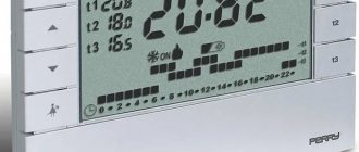
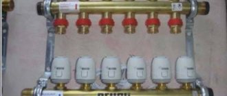
Setting the room thermostat
But after connecting the thermostat, it needs to be adjusted. Using the programmer panel, you can make settings. It contains keys and microswitches.
The following can be adjusted using microswitches:
- Set the temperature fluctuation mode;
- Air cooling and heating;
- Sensor response interval. If you open the balcony for a short time, the sensor will not work.
And using the keys you can set economical and optimal temperature conditions. During the day the required temperature will be maintained, and at night it will decrease, but be at a comfortable level and thus fuel savings will occur. There are also programs installed in room thermostats. From them you can choose the program that suits you.
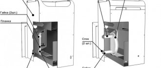
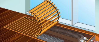
Installation of automatic heating regulators
The instructions below will help you install the thermostat on both aluminum and bimetallic radiators.
If the radiator is connected to a working heating system, then the water should be drained from it. This can be done using a ball valve, shut-off valve or any other device that blocks the flow of water from the common riser.
After this, open the battery valve, located in the area where water enters the system, and turn off all taps.
After the water has been removed from the battery, it must be purged to remove air. This can also be done using a Mayevsky crane
The next step is to remove the adapter. Before the procedure, the floor is covered with material that absorbs moisture well (napkins, towels, soft paper, etc.).
The thermostatic valve body is fixed using an adjustable wrench. At the same time, use a second wrench to unscrew the nuts located on the pipe and the adapter, which is located in the battery itself. Next, unscrew the adapter from the body.
When unscrewing the adapter, you may need to use the valve located inside the battery
After dismantling the old adapter, a new one is installed. To do this, place an adapter in the structure, tighten the nuts and collar, and then thoroughly clean the internal threads using a clean material.
Next, the cleaned thread is wrapped several times with white plumbing tape (purchased separately in specialized stores), after which the adapter, as well as the radiator and corner nuts are tightly screwed on.
The thread must be wrapped with plumbing locking tape clockwise, making 5-6 turns
It is important that the tape lays evenly, so it is necessary to smooth it out in a timely manner if necessary. As soon as the installation of the adapter is completed, you need to begin removing the old collar and installing the new one.
In some cases, it is difficult to remove the collar, so cut out its parts using a screwdriver or a hacksaw, and then tear them off from each other
Once the installation of the adapter is completed, you need to begin removing the old collar and installing the new collar. In some cases, it is difficult to remove the collar, so its parts are cut out with a screwdriver or a hacksaw, and then torn off from each other.
Next comes the installation of the thermostat itself. To do this, following the arrows shown on the body, it is installed on the collar, after which, fixing the valve with an adjustable wrench, tighten the nut, which is located between the regulator and the valve. At the same time, use a second wrench to tighten the nut tightly.
It is important not to damage the thread when installing the thermostat, and after tightening, check the strength of the connection in order to avoid leaks when turning on the water.
At the final stage, you need to open the valve, fill the battery with water, make sure the system is working, there are no leaks, and set a certain temperature. In a two-pipe system, you can install thermostats on the top supply.