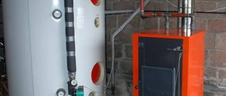
Owners of country cottages and private houses are increasingly abandoning traditional one- or two-pipe wiring and prefer a manifold distributor. This allows you to use fuel more economically and create comfortable conditions in each room separately. Agree that it is irrational to refuse to reduce heating costs, especially since the temperature in the premises will not suffer from this.
Are you also thinking about connecting a collector and want to learn more about this equipment? We will help you understand the topic - in this article we will look in detail at what the distribution comb of a heating system is and what its advantages are.
We will highlight the significant disadvantages of its use, describe the connection process in detail, providing the material with visual photos. We will also focus on the basic connection rules that it is advisable to follow. Here are useful video recommendations for installing and making your own comb.
Types of heating combs
Heating combs are available in many types - with a wide variety of bells and whistles.
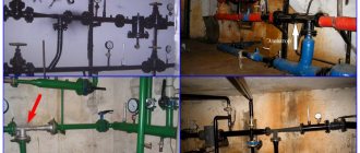
For example, like this:
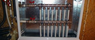
This is a very complex collector system and, at the same time, expensive, not everyone can afford it. It consists of flow meters (white “caps” are visible on the upper supply manifold) and thermal heads. Flow meters allow you to regulate the uniformity of coolant supply to the radiators. There are also brackets for mounting in a manifold cabinet or on a wall.
Thermal heads are installed on the lower – return – manifold, which cover/open the passage of the coolant leaving the system. This regulates the temperature of the returned coolant. Thermal heads can be used to adjust the temperature for each radiator separately, i.e. by adjusting the desired temperature in each room, as mentioned above.
Manifolds - brass tubes with an inch internal passage and threads at the ends - for connecting shut-off valves and pipelines. Well, there are outputs - usually half-inch - for connecting radiators. As you can see in the photo, there are plugs on the return manifold so that flow meters or thermal heads can be installed if desired.
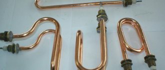
Another option for distribution manifolds is with a cast body:
On one side of the manifold there is an internal thread, on the other there is an external thread (inch or three-quarter).
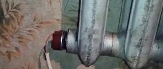
Well, the most budget option:
This is a heating comb of Chinese or Turkish origin. Metal-plastic pipes are connected to such a collector using the collet connectors available here.
Such collectors are quite functional, except for one of their weaknesses: it happens that the coolant begins to leak from under the valve handle. The reason is wear of the rubber seals. Unfortunately, it is not always possible to replace the seals, and the entire manifold has to be replaced.
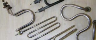
And this is the simplest heating comb:
It's just a stainless pipe with welded outlets. Such simplicity is deceptive: you understand, you need to buy a lot more for it. And stainless steel is not the cheapest material.
Design of different types of combs
The most affordable would be a distribution comb with manual shut-off valves made in China or Turkey. Metal-plastic pipes are put on the collet connectors located on it.
A budget distribution comb with valves has one significant drawback - water can drip from under the handle. Leakage occurs due to wear of rubber seals
Threads at the ends are needed for connecting shut-off valves and central hot water supply/discharge. In general, such a comb will cope with its function, but its flawless service life will not be very long.
If disassembling the valves and replacing worn seals does not lead to initial tightness, you will have to buy a new manifold.
A more complex design would be a comb with plugs on the return manifold (and on the direct one too). Instead of them, flow meters and thermal heads can be installed in the future. The direct and reverse combs in such models are already connected by a bracket for mounting on the wall.
The presence of plugs makes it possible, if necessary, to improve the heating distribution manifold. To avoid problems with the installation of thermostats and other components in the future, it is necessary to provide convenient access to the comb at the stage of its installation
And finally, a complex and expensive, but the most effective distribution comb with factory-installed flow meters and thermal heads.
Flow meters regulate the uniform delivery of coolant to its destination, and thermal heads can adjust the temperature for each outlet separately, just like for a heating radiator. The types of thermal heads, their operating principles and installation features are discussed in more detail in our other article.
Flow meter caps allow you to visually monitor coolant flow through the circuits. Thermal heads regulate the flow of coolant into each of them
Even during the design process, it is necessary to make a choice between different types of combs, but in any case, the collector system is a preferable choice compared to conventional wiring based on such criteria as ease of use and durability.
Advantages and disadvantages of collector heating
Collector heating in an apartment or private house has pros and cons. Among the advantages of this system it should be noted:
- Maintainability. If a breakdown is detected, you can easily turn off a separate section of the pipeline without completely interrupting the operation of the system.
- Small cross-section pipes can be used. Since each branch leaving the distributor feeds only one radiator, for its installation it is possible to choose pipes of a small cross-section, and they can be easily placed in the screed.
- Easy to use. Due to the fact that each device has autonomous control, the home owner has the opportunity to set the temperature in any specific room. And if necessary, turn off heating devices in the room. Moreover, the temperature in the remaining rooms will remain the same.
- You can install a collector heating system for a private house with your own hands.
Economic costs are one of the disadvantages of this heating.
In order to create several branches that have different characteristics, for example, different coolant pressures, distribution wiring with a hydraulic compensator is used. A hydraulic arrow is a capacious pipe where several independent branches are connected to the outputs.
Due to the fact that heated water reaches the radiators with minimal losses, the efficiency of the system increases. This allows you to reduce the boiler power, saving fuel costs.
The heating system also has disadvantages. The main ones:
- Pipe flow. In contrast to the classical connection, the pipe flow during the arrangement of the collector circuit increases by 2-3 times. The difference in costs is due to the number of premises involved.
- Circulation pumps are required, which will entail additional material investments.
If something happens to the pipes, you will have to open the floor
Another disadvantage is the dependence on electricity: even with the boiler running, the radiators will remain cold during a power outage. Therefore, these systems are not recommended for use in areas where power outages are common.
What you need to know about the cons?
After the advantages of using distribution combs in heating systems have become clear, it makes sense to dwell on some of the disadvantages:
- High price . Collectors are made of durable, high-quality metal, the cost of which is above average. High-precision locking equipment is also expensive. The more circuits a comb serves, the higher the cost of equipping it.
- Energy dependence . Collector heating without a circulation pump does not work. Therefore, you need to prepare for additional payments for electricity.
- High pipe flow . The consumption of pipes in collector heating systems is several times higher than in conventional ones, since a separate loop must be pulled to each device. All this complicates and increases the cost of installation work.
The collector system, according to experts and those who already use it, is the most modern, reliable and efficient.
But at the same time, both its arrangement and operation are expensive.
Sequence of work
The process of making a comb looks quite simple:
- It is necessary to purchase materials in accordance with the decisions made during the design phase of the distributor.
- Holes for bends are cut in the workpiece for the housing. If a round pipe is used for this purpose, then first you need to draw a hole pattern on paper (commonly called a “fish”). Next, the development is cut out, applied to the pipe and outlined with a pencil or marker. After this, a hole is cut out - with preliminary drilling along the contour or using a gas cutter.
- We weld the bends to the comb body using electric welding. Plugs are welded to the ends, which, if necessary, are also equipped with pipes.
- The resulting product must be checked for leaks. We leave one outlet open and close all the others tightly. After this, we fill the manifold with hot water and observe whether the welds will leak. It doesn’t hurt to get a hand pump for crimping and check the reliability of the seams under pressure.
It is not necessary to use a round pipe as the collector body; a square one will do just fine.
If the tests were successful, you can paint the comb and, after the paint has dried, begin its installation.
Even if a warm floor is installed in one room, it is still necessary. An overview of collector models and their prices is presented on the website.
Common house collector group
The main comb performs the same functions as the TP collector - it distributes the coolant among the branches of the heating network of various loads and lengths. The element is made of steel - stainless or black, the profile of the main chamber is round or square.
Reference. Factory-made main manifolds are called coplanar. This buzzword means that all the parts of the comb lie in the same plane - the vertical supply pipes completely intersect the “return” chamber and vice versa. The goal is to reduce the weight and dimensions of the structure.
There are compact models of distributors for 3–5 circuits, made in the form of one pipe. Here's the trick: the return manifold is placed inside the feed chamber. As a result, we get 1 common housing with 2 cameras of equal capacity.
In the vast majority of country houses with an area of up to 300 m², distribution manifolds are not needed. For several heat consumers, a piping scheme using the primary-secondary ring method is used, described in a separate article. When should you think about buying a communal heating comb:
- the number of floors of the cottage is at least two, the total area is over 300 square meters;
- for heating, at least 2 heat sources are used - gas, solid fuel, electric, and so on;
- the number of individual radiator heating branches is 3 or more;
- The boiler room diagram contains an indirect heating boiler, heating circuits for auxiliary buildings, and heating of the pool.
The listed factors must be considered separately and together, and to select a model of specific sizes, the load on each branch must be calculated. Hence the conclusion: it is better not to buy a collector without consulting an expert.
Drawing of a coplanar manifold and photo of the finished product with pumping groups
Calculation of comb throughput
The calculation of the parameters of the distribution comb includes determining its length, the cross-sectional area of its cross-section and pipes, and the number of heat supply circuits. It is better if the calculations are done by engineers using computer programs; in a simplified version, they are only suitable at the preliminary design stage.
In order to maintain hydraulic balance, the diameters of the inlet and outlet manifold combs must match, and the total throughput capacity of the nozzles must be equal to the same parameter of the collector pipe (the rule of total sections):
n=n1+n2+n3+n4,
Where:
- n is the cross-sectional area of the collector4
- n1,n2,n3,n4 - cross-sectional areas of the pipes.
The choice of comb must correspond to the maximum thermal output of the heating system. What power the factory product is designed for is written in the technical data sheet.
For example, a distribution pipe diameter of 90 mm is used for a power not exceeding 50 kW, and if the power is twice as high, the diameter will have to be increased to 110 mm. This is the only way to eliminate the risk of unbalancing the heating system.
The cross-section of the collector pipe is equal to 3 diameters of the connected pipes, the distance between the supply and return combs is 6 diameters, the distance of the pipes from each other is 3 diameters
The 3-diameter rule is also useful (see picture above). As for calculating the performance of the circulation pump, the specific water consumption in the heating system is taken as the basis.
Each pump is calculated separately - per circuit and for the entire system. The figures obtained in the calculation are rounded up. A little extra power is better than too little.
Areas of application of heating combs
The main purpose of the heating comb is to optimize and rationally distribute the coolant.
Without a correctly designed and installed distribution manifold, the heating may not operate correctly. The comb allows you to use all the useful power of the boiler, while obtaining maximum efficiency of the entire system. Collectors also allow you to include several consumer points in the system and be sure that the temperature of the coolant in all sections of the main will be the same. If you do not use a distribution comb, it often turns out that the radiator near the boiler is very hot, and the radiator, for example, on the second floor, is lukewarm.
This happens because the coolant cools down while it reaches the last battery. This effect can be avoided and the path of the coolant to the end consumer can be reduced by dividing it into specific circuits.
Modifications of distributor combs
Today, there are many types of collectors for heating systems on the equipment market.
Manufacturers offer both connecting links of the simplest design, the design of which does not provide for the presence of auxiliary fittings for regulating the equipment, and manifold blocks with a full set of built-in elements.
A collector block that includes all the necessary functional elements to create conditions for uninterrupted and high-performance operation of the heating system
The simple-to-use devices are brass models with one-inch branches, equipped with two connecting holes on the sides.
On the return collector, such devices have plugs, instead of which, in the case of “expanding” the system, additional devices can always be installed.
Intermediate assemblies that are more complex in design are equipped with ball valves. For each outlet they provide for the installation of shut-off control valves. Sophisticated, expensive models can be equipped with:
- flow meters, the main purpose of which is to regulate the flow of coolant in each loop;
- thermal sensors designed to monitor the temperature of each heating device;
- automatic air release valves for draining water;
- electronic valves and mixers aimed at maintaining the programmed temperature.
The number of circuits, depending on the connected consumers, can vary from 2 to 10 pieces.
Regardless of the complexity and versatility of the equipment, materials that are resistant to external factors are used in the manufacture of manifold block combs
If we take the manufacturing material as a basis, then intermediate prefabricated collectors are:
- Brass - characterized by high performance parameters at an affordable price.
- Stainless steel structures are extremely durable. They can withstand high pressure with ease.
- Polypropylene - models made of polymer materials, although they have a low price, are inferior in all characteristics to their metal “brothers”.
Models made of metal are treated with anti-corrosion compounds and covered with thermal insulation to extend their service life and improve performance parameters.
Separating structures made of polymers are used in the construction of systems heated by boilers with a power of 13 to 35 kW
Parts of the device can be cast or equipped with collet clamps, allowing connection to metal-plastic pipes.
Collectors are used in single- and two-pipe heating schemes. In single-pipe systems, one comb supplies the heated coolant and receives the cooled one
Recommendations for choosing wisely
The main difficulty lies not only in the installation of the collector itself, but also in the correct choice of equipment.
When choosing a comb model, you should focus on the following parameters:
- Maximum permissible pressure for this model. It determines the type of material from which the hydraulic valve can be made.
- Node throughput.
- Availability of auxiliary devices.
- Number of comb outlet pipes. It must correspond to the number of cooling circuits.
- Possibility of additional connection of elements.
All operational parameters are indicated in the product passport.
To install floor-by-floor independent heating circuits equipped with autonomous control, combs must be installed on each floor of the house.
When selecting and installing floor distributors, they are guided by the parameters of the “subsystem” that they are intended to serve.
Thanks to the floor-by-floor arrangement of the combs, if necessary, you can always turn off the heating of both several individual devices and the entire floor
This greatly simplifies the maintenance and repair of the heating system.
Since a collector block is not a cheap pleasure, in order to protect yourself from disappointment when the system quickly fails, when choosing a model, you should focus on products from trusted manufacturers.
You can safely trust such manufacturers as GREENoneTEC , Rehau , Soletrol , Oventrop and Meibes . In each series of leading European manufacturers you can select a complete set of necessary additional equipment.
Auxiliary elements and fittings for the collector block must also comply with GOST and TU.
As additional devices for connecting the manifold, you may need: 1 - automatic air vent, 2 - adapter, 3 - angle, 4 - tap, 5 - outlet, 6 - another angle, 7 - pipe outlets
Each of the additional structural elements performs its own function:
- automatic air vent - installed if the unit and radiators are located on the same floor;
- adapter - required when installing an air vent with a diameter of ½ inch, provided that the manifold thread is ¾ inch.
- corner - will allow you to connect the pipes and direct the air vent upward.
- tap – necessary to connect the pipe coming from the boiler to the device;
- a squeegee equipped with a cap nut will allow, if necessary, to shut off the coolant supply and, by unscrewing the cap nut, disconnect the device.
If you intend to connect a water heated floor from the collector, you will additionally need to install a tap for refilling.
To fix the collector to the wall, you will also need clamps mounted on plastic dowels. When installing the structure, it is also permissible to use special brackets.
Such designs are convenient in that the upper manifold in them is pushed forward, so that the pipes of the unit do not interfere with the pipeline supply to the lower manifold.
What is it needed for
When installing water pressure systems, there is a rule: the total diameter of all branches should not exceed the diameter of the supply pipe. In relation to heating equipment, this rule looks like this: if the diameter of the boiler outlet fitting is 1 inch, then the system allows two circuits with a pipe diameter of ½ inch. For a small house heated only with radiators, such a system will work effectively.
In fact, there are more heating circuits in a private house or cottage: heated floors. heating of several floors, utility rooms, garage. When they are connected through a tapping system, the pressure in each circuit will be insufficient to effectively heat the radiators, and the temperature in the house will not be comfortable.
Therefore, branched heating systems are made using collector systems; this technique allows you to adjust each circuit separately and set the desired temperature in each room. So, for a garage, plus 10-15ºС is enough, and for a nursery, a temperature of about plus 23-25ºС is required. In addition, heated floors should not heat up more than 35-37 degrees, otherwise it will be unpleasant to walk on them, and the floor covering may become deformed. With the help of a manifold and shut-off temperature, this problem can also be solved.
Video: using a collector system for heating a house.
Manifold groups for heating systems are sold ready-made, and they can have different configurations and the number of outlets. You can select a suitable collector assembly and install it yourself or with the help of specialists.
However, most industrial models are universal and do not always fit the needs of a particular home. Redesigning or modifying them can significantly increase costs. Therefore, in most cases it is easier to assemble it from separate blocks with your own hands, taking into account the characteristics of a particular heating system.
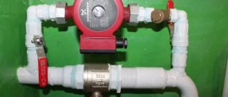
Manifold group for heating system assembly
The design of the universal collector group is shown in the figure. It consists of two blocks for forward and reverse coolant flow, equipped with the required number of outlets. Flow meters are installed on the supply (direct) manifold, and thermal heads are located on the return manifold to regulate the return water temperature in each circuit. With their help, you can set the required coolant flow rate, which will determine the temperature in the heating radiators.
The manifold distribution unit is equipped with a pressure gauge, circulation pump and air valves. The supply and return manifolds are combined into one unit with brackets, which also serve to attach the unit to a wall or cabinet. The price of such a block is from 15 to 20 thousand rubles. and if some of the taps are not used, its installation will be clearly impractical.
The rules for installing the finished block are shown in the video.
Comb - collector unit
The most expensive elements in a manifold distribution block are flow meters and thermal heads. To avoid overpaying for unnecessary elements, you can buy a collector unit, the so-called “comb”, and install the necessary control devices with your own hands only where necessary.
The comb consists of brass tubes with a diameter of 1 or ¾ inches with a certain number of taps with a diameter of ½ inch for heating pipes. They are also connected to each other by a bracket. The outlets on the return manifold are equipped with plugs that allow you to install thermal heads on all or part of the circuits.
Some models may be equipped with taps, with their help you can regulate the flow manually. Such combs have a cast body and are equipped with a fitting/nut thread at the ends, which allows you to quickly and easily assemble a manifold from the required number of branches.
In order to save money, the manifold for heating systems can be assembled from individual elements independently or completely made by hand.
Assembling a homemade manifold
The easiest way, of course, is to buy a ready-made unit - if, of course, you are able to shell out several thousand rubles for it. If not, you might as well purchase all the elements of the assembly separately and assemble it yourself. If it is a polypropylene version, you will need a special soldering iron and scissors for cutting pipes.
Everything you need to assemble a polypropylene manifold
Pipe shears
Prices for scissors for cutting polypropylene pipes
Scissors for cutting polypropylene pipes
Soldering iron
Then look at the pictures:
The piece of pipe and tee are heating up...
... after which the pipe is inserted into the hole of the tee and pressed tightly
Cut the pipe, leaving 2 cm
On the other side, solder a tube 20-30 cm long
At its second end, fix another tee
This way you can assemble a comb with any number of outputs
The same thing can be done using metal parts as a basis - the only difference is that they will be assembled on threaded connections. Otherwise, the entire principle of assembling the manifold is the same as in the case of the factory unit, which we presented in the previous chapter.
Prices for a soldering iron for polypropylene pipes
Soldering iron for polypropylene pipes
Installation of the comb in the heating system and its calculation
The installation location of the distribution comb in the heating system depends on its purpose. Most often it is used to organize multi-circuit heat supply. However, in addition to this, it is a mandatory element of a water heated floor.
Before proceeding with installation, you should calculate the heating comb. The main task of this process is the uniform distribution of pressure along the heating circuits. If the system is a complex circuit of highways, it is recommended to make calculations using special programs. For a simple system with up to 5 circuits, you can apply the principle of equal sections.
N0=N1+N2+N3+N4
Where N0
– diameter of the collector,
N1
,
N2
,
N3
,
N4
– sections of its outlet pipes.
The same calculation scheme is used when making a heating comb with your own hands
It is important that the dimensions of the inlet and outlet manifolds match. It is noteworthy that the standard heating comb device has no requirements for its shape
Those. it can be either round or square. The basic principles for installing collector heating are as follows:
- To improve circulation, it is recommended to install pumps for each circuit. In this case, the distribution comb of the heating system should not ensure synchronization of the pumps;
- If the unit is located in a boiler room, installation of a protective box is not necessary. An exception is the installation of a heating comb made of polypropylene in a heated floor system;
- To adjust the coolant volume, it is necessary to install control fittings on each inlet and outlet pipes - inlet valves and balancing flowmeters;
- When planning the installation of a heating comb, it is necessary to provide for the presence of a safety group at the distribution unit.
In addition to these rules, experts advise when calculating the heating comb to take into account the difference in the length of the circuits. It is recommended to draw up a diagram so that their length is approximately equal.
To reduce energy consumption, a mixing unit can be installed in the heating comb device, which, in turn, will reduce heating costs.
Connection rules and installation features
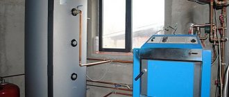
Installation of the comb begins with attaching it with brackets to the wall, where it will be located openly or in a closet. Then you will need to attach the main pipes from the heat source to the ends and begin piping.
Option #1 - without additional pumps and hydraulic arrows
This simple option assumes that the comb will serve several circuits (say, 4-5 radiator batteries), the temperature is assumed to be the same, and its regulation is not provided. All circuits are connected directly to the comb, one pump is used.
The characteristics of pumping equipment must be correlated with the performance of the heating system and the pressure created in it. So that you can choose the best pump that is ideal in terms of characteristics and cost, we recommend that you familiarize yourself with the rating of circulation pumps.
A master with experience in manifold equipment knows how to correctly install a distribution comb and hide it in a cabinet so as to hide all the pipes
Since the resistance in the circuits is different (due to different lengths, etc.), it is necessary to ensure optimal consumption of the coolant by balancing.
To do this, balancing valves, rather than shut-off valves, are installed on the return comb nozzles. They can regulate (although not exactly, but by eye) the coolant flow in each circuit.
Option #2 - with pumps on each branch and a hydraulic arrow
This is a more complex option, which will be needed if necessary to power consumption points with different temperature conditions.
So, for example, in radiator heating, water heating ranges from 40 to 70 °C, a warm floor needs a range of 30-45 °C, hot water for domestic needs must be heated to 85 °C.
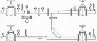
In the piping, the hydraulic arrow will now play a special role - a section of pipe that is blind at both ends and has two pairs of bends. The first pair is needed to connect the hydraulic needle to the boiler; the distribution combs are connected to the second pair. This is a hydraulic barrier that creates a zone of zero resistance.
For boilers with a power of 50 kW and above, it is recommended to use a distribution comb together with a hydraulic arrow. It is mounted vertically on the wall with separate brackets to avoid excessive horizontal overload
On the comb itself there are mixing units equipped with three-way valves - temperature control devices. Each outlet pipe operates its own pump independently of the others, providing the specific circuit with the required amount of coolant.
The main thing is that the total power of these pumps does not exceed the main boiler pump.
Both options considered are used when installing distribution manifolds for boiler houses. Everything you need is sold in specialized stores. There you can buy any assembly assembled or element by element (counting on savings due to self-assembly).
To further reduce future costs, you can make a heating distribution comb yourself.
The boiler room manifold is located in close proximity to the heating equipment and is exposed to high temperatures that only metal can withstand.
The local distribution comb is subject to less stringent requirements for heat resistance; not only metal pipes, but also polypropylene and metal-plastic pipes are suitable for its manufacture.
For a local distribution manifold, the easiest way is to select suitable scallops from those that are commercially available. In this case, you should take into account the material from which they are made - brass, steel, cast iron, plastic.
Cast scallops are more reliable, eliminating the possibility of leakage. There are no problems connecting pipes to the manifolds - even the most inexpensive models have threads.
Distribution combs assembled from polypropylene parts are attractive due to their low cost. But in an emergency, the joints between the tees will not withstand overheating and will leak
Craftsmen can solder a manifold from polypropylene or metal-plastic, but they will still have to buy threaded tips, so the product will not be much cheaper in terms of money than a ready-made one from the store.
Externally, it will be a set of tees connected to each other by tubes. The weak point of such a collector is insufficient strength at high heating temperatures of the coolant.
The comb can be round, rectangular, or square in cross-section. Here, the transverse area comes first, rather than the cross-sectional shape, although from the standpoint of hydraulic laws, rounded is preferable. If the house has several floors, it is better to install local distribution manifolds on each of them.
Making a distribution manifold with your own hands
The distribution manifold design is developed based on the number of heating circuits in your system. Assess where your heating boiler is located, what inlet and outlet pipes it has, how many heating circuits or indirect heating circuits will be used in the heating system. Perhaps you are planning to increase the number of circuits in your home, for example adding another room next year. Solar collectors, heat pumps and other devices can also be connected to the distribution system. We also consider all heat distribution systems, including warm water floors, heating radiators, fan coil units, and so on.
We are drawing up a diagram of our heating system, taking into account that each circuit has a hot water supply pipe and a return pipe.
When designing the system, do not forget to determine the location of additional equipment, such as an expansion tank, an automatic make-up valve, a drain and fill valve, a group of thermostats, and so on.
Performs spatial design, that is, we determine where and where pipes will be connected to our distribution manifold. Practice suggests that pipes for connecting a solid fuel boiler and for indirect heating are usually installed at the ends of the collector. If you have a wall-mounted gas or electric boiler in your system, it fits into the top or also into the end.
Based on the available information, we draw up a drawing of the future distribution manifold. It is convenient to use graph paper for this. The distance between the pipes should not be less than 10 centimeters, but they should not be spaced wider than 20 centimeters either. For one heating circuit, the distance between the supply pipe and the return pipe should not be less than 10 centimeters. It is desirable that groups of pipes of the same circuit be visually distinguished.
Collector design
The figure below shows an example of designing a distribution manifold into which six heating system circuits will be connected.
At the first stage, we draw two rectangles. This is the supply manifold and the return manifold.
supply manifold and return manifold
We design the connection of the boiler and indirect heating boiler on the manifold trunks. Do not forget to indicate on the drawing the cross-sectional parameters of future pipes.
connecting the boiler and indirect heating boiler
We design the connection of heating circuits and additional heating boilers. Don’t forget to indicate the cross-section of the pipes and the dimensions of the pipes. We sign all designed pipes.
connection of heating circuits and additional heating boilers
At the next stage, we design the connection of additional equipment. In our case, this is an expansion tank, a drain valve, a protective block, and a system thermometer
Please note that the coolant supply circuits are highlighted in red, and the return circuits are highlighted in blue
connecting additional equipment
This was a rough drawing. We check its correctness and transfer it completely to a new sheet of paper. It is based on this project that we will create our own distribution manifold.
finishing drawing
Comb device for heated floors
The temperature of the coolant supplied to the underfloor heating circuits should not exceed 50 °C, the optimal temperature schedule is 40/30 °C. If the floor surface heats up above 30 degrees, the room will become stuffy and uncomfortable.
Only gas boilers are capable of maintaining a supply of 40–50 °C, and even then with a loss of efficiency. To effectively consume gas or other energy carriers, water must be heated to 60 degrees, and then the temperature at the entrance to the transformer loops must be reduced. This is one of the main tasks of the collector block, consisting of the following elements:
- the collector itself – 2 separate tubes (supply and return) with wall mounting brackets;
- thermostatic pressure valves with connection for Eurocone pipes;
- flow meters (rotameters) with a scale of 0.5…5 l/min;
- end blocks with automatic air valves and drain valves;
- dial thermometer blocks;
- shut-off ball valves;
- bypass line with bypass valve.
Distributor design for underfloor heating systems
Rotameters and pressure valves are screwed into special sockets on the comb, the latter are closed with plastic caps. Air vents with drain valves are screwed into the ends of the collector tubes on one side, and blocks of thermometers and taps on the other. The bypass is installed depending on the design of the comb.
Note. Typically, flow meters are located on the supply line, thermal valves are on the “return” line. But there are also other models of collectors with rotameters on the return line. If you mix up the distributor tubes, you won’t be able to twist the valves instead of the flow meters - the internal shape of the bushings is different.
The thermometers are followed by ball valves, followed by a circulation pump and a mixing unit. Let's consider each element of the collector group separately.
Design and purpose of flow meters
Rotameters are designed to monitor and regulate the maximum fluid flow through loops. The elements are screwed into special pipes on the manifold without winding materials - the seal is an EPDM rubber gasket.
The flow meter body contains a spring-loaded rod with a working plate at one end and a control washer at the other. How does a rotameter work:
- The coolant flows through the side hole in the housing, then moves down, presses on the plate and goes into the pipe. To adjust the maximum flow on the flow meter using the adjusting washer, you need to remove the protective plastic cap
- The more water flows through the flow meter, the greater the pressure on the plate. The spring is compressed, the rod with the control washer is lowered. The flow rate in l/min can be observed on the scale marked on the transparent bulb of the element.
- The amount of flow is regulated by rotating the upper part of the housing. When twisting, the passage hole is partially or completely closed by the piston.
Reference. Some manufacturers' collectors are equipped with unregulated rotameters. To limit flow, separate valves built into the pipe body are used. See the video below to see how such elements look.
Flow meters installed on the return line are designed similarly, only the spring is on the other side of the control washer. The coolant enters from below and pushes the plate upward, the rod and washer rise. How to distinguish between different types of rotameters:
- if, in the absence of flow, the washer is at the top of the flask, then the flow meter is placed on the supply;
- if at zero water flow the washer is at the bottom of the scale, the element is intended for “return”;
- the scale on the flask is graduated in the appropriate direction, in the first case the counting is from top to bottom, in the second – from bottom to top.
During operation, rotameters must be maintained - cleaned when dirty. A transparent bulb serves as an indicator; when it becomes coated from the inside, the element should be unscrewed, disassembled and dirt removed from the working surfaces.
How does a thermostatic valve work?
Structurally, the product is no different from other similar thermal valves - radiator or two-way. When you press the spring-loaded rod, the plate lowers into the seat, blocking the passage of the coolant. It is possible to preset: the maximum flow rate is limited by rotating the valve core using a hex key.
Clarification. There are 2 types of valves - normally open and normally closed. The first ones are described above - when you press the rod, the passage closes. The latter are used less frequently, where the channel is initially closed, and when the rod is lowered, the hole opens.
The purpose of the thermostatic valve is to regulate coolant flow during operation (not balancing!). Management is implemented in 3 ways:
- Manual. The position of the rod is adjusted by a plastic handle, which is screwed onto the valve from above.
- Automatic RTL thermal heads that press the rod when the return flow temperature increases. Do not confuse them with conventional radiator heads that respond to air temperature.
- Electric servos connected to room thermostats or weather-dependent automation.
Manual control requires constant attention from the user - when the ambient temperature changes, you will have to press or release the rod. Thermal heads of the RTL type automate the process, but work well only on short loops - up to 60 m. Servo drives plus thermostats are applicable everywhere.
Other comb accessories
At the beginning of the publication, we listed the tasks that the underfloor heating collector group must solve. With balancing and flow control it is clear - these functions are performed by rotameters and valves. Let's move on to the remaining accessories:
- Terminal unit for emptying and automatically removing air bubbles. The element consists of a housing with a drain valve and a float air vent. The fitting is closed with a plug, which at the same time serves as a thumb for opening the valve.
- Blocks of dial thermometers marked up to 80–90 °C. The purpose is clear - measuring the temperature at the inlet and outlet of the comb.
- Ball shut-off valves. Depending on the method of connecting the collector to the heating, straight, angular, American and internal/external threaded taps are used.
- A bypass jumper with a bypass valve is used in systems with automatic control. If, due to warm weather, all circuits are closed, the coolant will flow through the bypass in a circle, the pump will not work on its own. In normal mode, the valve will not allow water to circulate directly and will force it to move in loops.
From left to right: drain end fitting with manual air valve, block with automatic air vent, ball valves and thermometers
Note. Through the terminal unit, you can not only drain the coolant, but also pump it in in case of repairs. The collector is cut off from the main line by taps, and the TP circuits are emptied or recharged through a side fitting.
The number and variety of additional fittings depends on the comb manufacturer. These accessories are the main ones; in addition to them, various plugs, adapters and valves are also used.
A mixing unit is located in front of the collector block; its composition depends on the method of preparing the coolant for the TP. There are 3 methods of bringing water in heated floors to the desired temperature:
- Mixing into hot water circuits with a two-way thermostatic valve. The element launches portions of the coolant at the command of a thermal head with an external temperature sensor in the form of a copper flask. The latter is attached to the metal wall of the manifold and connected to the head through a capillary tube.
- Mixing cooled and heated coolant using a three-way valve. The principle is as follows: the pump drives water through the bypass along the circuits; when it does not cool down, the valve opens the supply of heated water from the boiler line. The difference from the previous method is a smoother flow and mixing quality.
- Restriction of reverse flow by RTL thermal heads installed on the comb thermal valves. Here a pump module is not needed at all.
You can control a two- or three-way valve in three ways: manually, using a thermal head with a remote flask and an electric actuator. The latter is controlled by a controller that receives signals from room or weather sensors.
Classification of distribution manifolds
Distribution manifolds differ from each other in the type of wiring, the material from which they are made and technical characteristics.
Solar collectors save energy. In any weather, they heat up to eighty degrees from the sun, due to this the system does not require electricity consumption.
You can make a solar collector using antifreeze as a coolant with your own hands.
If the heating system has a lot of heating devices, which means that independent branches go from the collector to them, it is necessary to use a hydraulic arrow, which will distribute the flows and ensure uniformity of pressure and temperature. Allows you to mix streams. The use of a hydraulic arrow is rational if the heating system is complex.
Simple collectors make it possible to connect/disconnect several heating devices; they are not equipped with additional devices; therefore, they do not allow changing the temperature, as well as pressure, mixing flows, etc. They are easy to install and easy to use, hence the name.
Improved distribution manifolds regulate temperature and pressure using included devices, equipped with automatic sensors and fittings.
Among the additional equipment that is needed to ensure operating comfort when using a distribution manifold are various valves, sensors, thermostats, blocks, air vents and mixers.
Collectors are made from:
- Brass
- Become
- Polymer materials
Brass manifolds are of fairly high quality and at the same time have a low cost.
Stainless steel manifolds can withstand high pressure and are durable. Polypropylene ones are inexpensive, but their quality is very poor.
Choosing a location for installing the heating collector
Before connecting the heating collector, check the installation location for any interference. Such a distribution heating system involves floor-by-floor installation of pipelines. An independent heating circuit with autonomous control is organized for each floor. In this case, the parameters of the subsystem they serve are taken into account.
The unit is installed in a separate niche just above the floor. The location of the device is selected at the design stage of the house. If this was not provided, then the collector can be placed anywhere by hiding it in a closet. The main requirement is the optimal humidity of the room where the heating distribution unit will be located. A closet, corridor or dressing room is suitable for this purpose.
You can make a cabinet for a distribution unit yourself or purchase it ready-made from a manufacturer that produces shut-off valves. The design is represented by a metal box with doors. The end walls of the product have holes for laying system pipelines.
If there are no aesthetic requirements for the installation location of the collector, then it can be attached to the wall in an open form using special clamps.
You can make a cabinet for the distribution unit yourself or purchase it ready-made
Areas of application of heating combs
The main purpose of the heating comb is to optimize and rationally distribute the coolant. Without a correctly designed and installed distribution manifold, the heating may not operate correctly. The comb allows you to use all the useful power of the boiler, while obtaining maximum efficiency of the entire system.
Collectors also allow you to include several consumer points in the system and be sure that the temperature of the coolant in all sections of the main will be the same. If you do not use a distribution comb, it often turns out that the radiator near the boiler is very hot, and the radiator, for example, on the second floor, is lukewarm.
This happens because the coolant cools down while it reaches the last battery. This effect can be avoided and the path of the coolant to the end consumer can be reduced by dividing it into specific circuits.
How not to make a mistake when choosing a distribution comb
Before purchasing a device, it is important to consider every little detail. Correlate all the functions that will need to be performed in the future comb. In this case, special attention should be paid not to the material, unfortunately many people look only at it, but also to other important factors.
What to pay attention to first:
- The throughput capacity of the purchased device - it is important that it copes with the flow of water to all nodes.
- What pressure in the system is the comb designed for?
- Energy consumption based on each connection point.
- Possibility of expansion when new water supply units appear in the house.
Choosing the right distribution comb is an important job that is difficult to do on your own, especially if a person understands nothing at all about this difficult matter.
Types and qualifications of distribution combs
As mentioned above, the device is designed for cold and hot water. For even more convenient use, they are available in two colors - blue and red. This allows you to avoid confusion during installation and technical work, which makes life much easier in the future.
Types of combs are divided into 3 types:
with 2, 3 or 4 branches. The choice depends on the wishes of the owner and the number of water supply nodes in the room.
If in your case there are 5 nodes you don’t need to despair, there is a solution - you can purchase a comb with 2 and 3 outlets and connect them together during installation. A significant advantage of collector pipe routing is that thanks to it it is possible to install a hidden gasket. This is ideal for the previously planned interior of the room in which the comb will be installed.
From a safety point of view, the distribution comb is one of the safest pipe layouts. After its installation, residents are not in danger of burst pipes and hot water leaking out, since it stabilizes its flow. If the building has several floors, wiring should be installed on each of them. The design of the device is very convenient, the pipes go from the risers directly to the distributor, and only then to all existing plumbing fixtures in the house. When installing, it is important to maintain an equal distance between the comb and the final device.