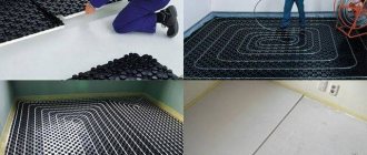
Creating a comfortable microclimate is the main task of any type of heating. In our country, for a long time, heating was done using traditional methods - stoves and solid fuel or gas boilers. Today, underfloor heating systems are becoming increasingly popular; they have undoubted advantages over traditional methods of heating rooms.
But it is not always possible to completely heat a house using TP. Therefore, a combined heating method is most often used, when water heated floors and radiators work in one heating system.
What is combined heating
Combined (mixed) is a heating system that contains both traditional high-temperature (conventional radiators, convectors) and low-temperature (warm floors, less often warm walls) heating devices.
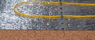
Water floors in a combined system are connected in two ways:
- For existing heating boilers . The advantages of this solution are a reduction in the estimated cost of equipment and a reduction in installation time. Disadvantage - additional heating cannot function in autonomous mode. This causes an increase in thermal energy consumption, and the efficiency of using heated floors decreases.
- Install hotel boilers for floor heating . The disadvantage is a significant increase in cost. Advantages: complete autonomy; water floors can be used independently of radiators. This may be necessary for a small heating of the room when the batteries are already turned off, for example, in the autumn-spring period.
Important! In apartment buildings, connecting water floors to the existing heating system is prohibited!
1st floor - heated floor, 2nd floor - radiators
What criteria do you use to choose boilers?
This is a rather complex question; to make the right decision, you need to look at it in more detail. From the point of view of installing additional heating systems, the technical indicators of the boilers are not of great importance; they all generate thermal energy in sufficient quantities, which makes it possible to connect the systems. But in practice, not everything is so simple. What types of heating boilers are there?
| Boiler type | Technical specifications |
Gas | The optimal choice for combined heating systems. It can operate fully automatically and has excellent efficiency indicators. There are products on sale that differ in size, installation method (floor and wall), thermal power, number of circuits (single and double circuit), installed electrical equipment and fittings. A wide range of technical parameters and costs allows all buyers to choose the option that suits them. The only problem is that not all regions of our country have gas pipelines. |
Electric | A modern boiler that fully meets stringent safety requirements, degree of automation and efficiency. It can connect to “smart home” systems, which significantly improves the microclimate parameters in the premises and saves energy. It has two drawbacks. The first is known to everyone - high power puts forward special requirements for electrical wiring; approvals from regulatory organizations are required. The second drawback is known only to practitioners. The water is heated by a special heat element, its surface area is insignificant. In many regions, the water is very hard, and solid salts are deposited on the heating element. A deposit thickness of just one millimeter reduces the efficiency by approximately 5–10%. In addition, because of them, the heat exchange process between the heater and water deteriorates; its heating temperature exceeds the critical one, which causes rapid failure of the device. As for various filters for purifying water from salt solutions, their actual capabilities are very far from those advertised. |
Solid fuel | Most often used in dachas or suburban villages where there is no natural gas. Modern models increase the fuel burning time, which simplifies the operation of the boiler. But connecting them to combined heating systems is not recommended due to the difficulty of adjusting the temperature of the coolant. |
All modern solid fuel boilers have one more significant drawback; manufacturers do not mention it.
Problems of solid fuel boilers
Why do professionals strongly discourage connecting solid fuel boilers to combined heating systems? We will not dwell on the fact that the heating temperature of the coolant does not depend on the wishes of the residents, but on the physical characteristics and parameters of fuel combustion; most consumers understand this. Solid fuel boilers have another unpleasant drawback.
An increase in efficiency can be achieved in one way - by increasing the amount of transferred fuel energy (fire and smoke) to a water container. This is achieved by increasing the contact surface area and the duration of energy transfer. The dimensions of the container have a direct impact on the dimensions of the boiler; this parameter cannot be abused. To increase heat transfer, designers additionally slow down the combustion process by limiting the supply of oxygen to the fuel, so it burns for a long period of time. But reducing oxygen automatically reduces draft and smoke temperature.
Long burning solid fuel boiler
As a result of combustion, all types of solid fuel produce a lot of ash and soot; with a lack of oxygen, their amount increases even more. The fuel has a certain moisture content and steam is released during combustion. The steam condenses on the walls of the chimney, soot sticks to it and over time the draft completely disappears. This situation can lead to tragic situations.
Accumulation of soot on the internal walls of the chimney
Important. For solid fuel boilers there is one important indicator. The smoke temperature at the outlet of their chimney cannot be lower than +120°C; under such conditions, the pipes do not become clogged. None of the existing solid fuel boilers meets this requirement.
In houses with ordinary stove heating, chimneys are periodically cleaned with strong combustion; in modern closed heating systems this cannot be done. The water may boil, but the installed expanders are of a closed type. The result is a rupture of plastic pipes, a boiler, or a violation of the sealing of fittings.
Features of the combined system
Key points to pay attention to when implementing a combined heating system for a private home:
- It is necessary to create two independent temperature conditions in the heating system - for the radiator circuit and the water floor circuit. The fact is that batteries require a relatively high supply/return temperature (not higher than 70/55°C for modern heating systems). At the same time, a heated floor requires a relatively low temperature (about 40/30°C). Modern boilers cannot solve this problem by themselves using standard means.
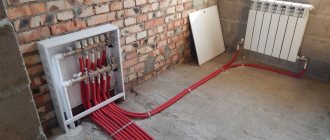
- Therefore, the use of additional components is required: mixing valves, circulation pumps, shut-off valves, etc., which require not only additional purchase costs, but also technically correct connection with the boiler.
- To regulate a combined heating system, the selection of appropriate technical means and their correct coordination is required. Mixing units with regulation using thermostatic valves, electronic regulation of supply temperature or weather-dependent control by an external controller or by means of the boiler itself, control of heated floors using room sensors (thermostats), operating logic of circulation pumps, etc.
Electric floor heating control
Here are the control diagrams for underfloor heating in the classic version and via PLC:
Classic control - through the thermostat in the room. The thermostat can be simple or programmable (with the ability to set on and off times). When controlled with a PLC, there are no thermostats; the temperature is controlled by the controller program, and the program is set by the user from a tablet/smartphone.
Why is there not a lot of TP in the house?
It should be noted that if you decide on water heated floors, there is little point in limiting their area . Let's say, do them only in two bathrooms and a hallway (the area of the TP will be about 20 m²). The best solution would be to install water heating wherever tiles are planned (usually hallways, halls, kitchens, pantries, and even living rooms, heated basement), and, if possible, in other rooms of the house, even bedrooms.
There are a number of reasons for this:
- A slight increase in price for a comfortable home. When implementing a water heated floor, even in a small area if there are radiators in the heating system, you will have to make a mixing unit with adjustment and pumps, buy a manifold and tie it with shut-off valves and pipes. Whether this mixing unit will work on 10 m² or 100 m² TP does not play a significant role. And the cost in both cases will be almost the same, because the shut-off valves, mixing valves and circulation pumps will be the same. Yes, the TP collector will, say, not have 2-3 circuits, but 10, but it will cost not 3-5 times more, but 2 times more.
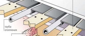
- The screed will still be all over the floor. If you install heated floors only in some of the rooms within the floor, you still face the question of pouring screeds over the entire area of the house (floor). This is necessary so that you do not have steps and thresholds between rooms: this is inconvenient, unsafe, and simply ugly. There is no difference when pouring floors over a floor slab, insulation on a slab, or over insulation with warm pipes - it will cost the same (the price is based on the area of pouring). But then it will be very difficult to remodel and add water heating in other places in the future, and more often than not, it will be simply impossible.
- Insulation of the ground floor floor. This immediately raises the question of insulating floors in those rooms where, although there is no water heating, it is necessary to insulate them. This applies to ceilings above basements and floors on the ground. In all houses this is necessary to reduce heat loss.
Thus, the difference in money when increasing the heating area will be determined only by the cost of the pipe for the heated floor and the cost of its installation.
Heating radiators
The technical parameters of heating radiators have a significant impact on the efficiency of the entire system.
| Type of radiators | Technical and operational parameters |
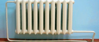
Cast iron | Traditional, but outdated elements are large in size and weight. Withstand operating pressure up to 10 atm, test pressure more than 15 atm. Service life is at least 50 years, it is possible to change the number of sections of one battery. Compatible with all standard pipelines, heat output is within 120 W, but this figure can vary significantly depending on the number of paint layers and the thickness of the dust. Disadvantages - ugly design, the peculiarities of the production process do not allow creating a modern appearance. |
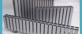
Aluminum | They have low weight and high heat transfer. Working pressure up to 12 atm., have a more modern design. The number of sections may vary depending on the size of the premises. The cost is significantly higher than cast iron. |
Bimetallic | The main metal is aluminum, the tubes are made of steel (increases resistance to high pressure). The most expensive radiators have an excellent design. |
Steel (panel) | Currently used quite rarely. Advantages - low cost. Disadvantage - there is a high probability of leaks in poor-quality welds, small heat transfer area. Another drawback is that steel radiators have standard sizes. |
Practical advice. Choose radiators with the largest heating area; all other advantages are advertising gimmicks of manufacturers. The coefficient of all metals and alloys without exception is almost the same; a slight difference does not play any noticeable role.
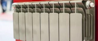
Prices for Rifar heating radiators
Heating radiators Rifar
Classic installation scheme
Let's consider a standard piping scheme for wall-mounted gas boilers tested and recommended by equipment manufacturers in combined heating systems with radiators and water-heated floors.
Scheme of combined heating from one boiler
Designation of the main elements of the circuit:
- wall-mounted gas boiler with built-in circulation pump and expansion tank;
- hydraulic separator (thermohydraulic separator or hydraulic arrow);
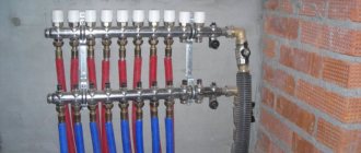
- collector (collector beam) for connecting heating circuits;
- radiator heating circuit circulation unit;
- mixing unit for water heated floor kennel;
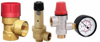
- safety thermostat.
Operating principle and purpose of the main components.
Wall-mounted gas boiler 1 (it can also be an electric boiler or any other) heats the coolant and, using the built-in circulation pump, supplies it to the thermo-hydraulic separator 2 (hydraulic arrow).
A hydraulic arrow, in fact, is nothing more than a piece of large diameter pipe with four bends. That. the heated coolant constantly circulates in a closed circuit boiler-arrow (A-B)-boiler.
When the pumps of the radiator circuit 4 and/or the heated floor circuit 5 are turned on, heated water is supplied from the hydraulic needle 2 (C-D) through the manifold 3 to the radiators and the heated floor. Water enters the radiator circuit 4 at the same temperature to which it was heated by the boiler, and in the mixing circuit of the heated floor 5, the water lowers its temperature in the mixing unit (in this example, using a three-way mixing valve) and enters the heated floors.
The hydraulic arrow in this diagram is needed for the following purposes:
- ensures constant circulation of coolant through the boiler, independent of the heating circuits, via a boiler pump;
- ensures the independence of the operation of circulation pumps in the circuits of radiators 4 and heated floors 5 from the boiler pump 1 and from each other;
- facilitates hydraulic calculation of the heating system;
- serves as a place for additional deaeration and collection of sludge from the coolant (see air vent and drain valve on the arrow).
Simplified connection option
Here is our proposed solution for a mixed home heating system with radiators and heated floors. The first picture is a version of the mixing unit with a three-way valve, the second is with a two-way valve. Both options are equally functional, however the second option may be more suitable for a larger area of underfloor heating, it all depends on the characteristics of the mixing valves.
With 3-way mixing valve
With 2-way mixing valve
The pictures show:
- heat source (wall-mounted gas or electric boiler) with a built-in pump, expansion tank, safety valve, etc.;
- bypass valve for the radiator circuit;
- mixing valve for underfloor heating (three-way or two-way);
- circulation pump for water heated floors;
- bypass valve for underfloor heating circuit;
- safety thermostat;
- balancing valve on a mixture for a two-way mixing valve.
Using the built-in pump
In this scheme, it is proposed to use a boiler pump, which is built into almost any household wall-mounted boiler of good power (up to 35 kW) to circulate the coolant in the radiator circuit. It would be unreasonable not to use its potential and further complicate and increase the cost of the heating system.
Expert opinion
Sergey Permyakov
Heating systems engineer
Circulation pumps built into wall-mounted boilers provide a pressure at the boiler outlet of about 20 - 25 kPa at coolant flow rates of 1000 - 1500 l/h. For example, for a Baxi Luna 3 Comfort 24 kW boiler, the coolant flow will be 1100 l/h with a pressure drop at the boiler outlet pipes of 25 kPa. Such a supply with a temperature difference ΔT=20°K can provide a heating power of 24 kW. This means that if the radiator circuit has a hydraulic resistance of no more than 25 kPa, then the pump built into the boiler will be enough to transfer the full power of the boiler (24 kW) to the radiator circuit.
In order to take advantage of the potential of the boiler pump, and even ensure circulation through the heated floors in a separate circuit, they must be properly linked to each other. This is achieved in our scheme by organizing the so-called. ring circuit .
The boiler room circuit contains two independent coolant circulation rings: 1. boiler circuit (boiler-radiators-boiler); 2. TP circuit.
These two rings have one region C-D in common with each other. Structurally, it consists of two closely spaced tees with outlets to the heated floor circuit. The close location of the tee branches (at a distance of no more than 100 - 200 mm from each other) guarantees low hydraulic resistance of this section C-D, and therefore little influence of the circuits on each other. This is a kind of analogue of a hydraulic needle, only without the functions of a sludge trap and air separator.
The function of a sludge trap will be performed by an oblique mud filter with a mesh, which must be installed in the heating system, and there are air vents in the boiler itself (automatic), radiators and on the underfloor heating manifold.
Operating principle of the ring circuit
The water heated in the boiler enters the radiator circuit supply (point A). Due to the pressure difference between the supply and return pipes of the boiler, the coolant passes through the radiators and returns to the boiler along the path: boiler supply-A-radiators-B-C-D-boiler return.
A bypass valve 2 is installed between points A and B, which we set to a pressure drop of 20 - 25 kPa. This means that as long as all or most of the radiators are open, the main coolant flow goes through the radiators themselves, and not through bypass valve 2. When part of the radiators is closed, excess coolant begins to pass through bypass valve 2. When the radiators are completely blocked (mode " only underfloor heating"), the entire flow passes through valve 2.
Expert opinion
Sergey Permyakov
Heating systems engineer
Thus, a constant coolant flow is maintained in the boiler circuit. This, firstly, has a positive effect on the operation of the boiler heat exchanger itself, and secondly, the full flow of coolant is also always maintained in the CD ring section, from which we can remove heat for the needs of the heated floor.
When the circulation pump of the underfloor heating circuit 4 is turned on, the pressure difference it creates forces part of the coolant from point C to flow into the three-way mixing valve and, accordingly, at point D to return cooled from the underfloor heating circuit to the return of the boiler ring. Regardless of the speed at which pump 4 operates, how open valve 3 is, or how many underfloor heating loops are running at the moment, the amount of water entering tee C is equal to the amount of water leaving tee D into the boiler. Those. the amount of coolant passing through the boiler ring is constant.
When the boiler pump is turned off (the boiler stops when the required temperature is reached), parasitic circulation does not occur through the boiler heat exchanger. The coolant circulates around the ring of the heated floor circuit and only in the CD section of the boiler ring.
When the heated floor pump 4 is turned off and the boiler pump is turned on (the “radiators only” mode), the pressure drop in the CD section is not enough to cause parasitic circulation in the heated floor circuit. Check valves become unnecessary.
Bypass valve 5 in the heated floor circuit ensures minimal coolant circulation when the heated floor loops are closed. It can be omitted if the pump is frequency-controlled or if room-by-room automation for heated floors with a circulation pump control module is used.
Safety thermostat 6 is installed on the supply pipe of the heated floor circuit and if the temperature in the circuit exceeds 50°C, it turns off pump 4.
In a circuit with a two-way thermostatic valve, valve 7 is necessary to balance the degree of mixing of the coolant in the underfloor heating circuit. Its position is adjusted during commissioning of the heating system.
Eventually:
- It is possible to dispense with a hydraulic needle, an additional circulation pump for the radiator circuit and their piping elements without compromising the functionality of the heating system; only correct calculation is required;
- The controllability of the heating system is simplified and the operating costs for electricity for the third pump are reduced (savings of about 20 - 40 kWh per month).
Typical errors of combined systems
The desire to save money leads to various variations of the proposed schemes. In the process of simplification, sometimes important elements are excluded and the heating system ends up looking like this:
But it’s still wrong to do this because:
- In this scheme there is no decoupling (independence) of the two remaining pumps of boiler 1 and the heated floor circuit 3, because they are connected to the common points of the circuit A and B, between which there is a large hydraulic resistance. In contrast to the circuit with a hydraulic arrow, where there is very little resistance between points A and B (D and C) (that’s why it’s a hydraulic separator).
- In some situations (when all radiators are closed and the heated floor is running), the boiler pump and the underfloor heating pump work sequentially, interfering with each other. This leads to changes in the coolant flow through the boiler heat exchanger.
- In situations where both radiators and underfloor heating are operating, the underfloor heating pump 3, at certain positions of the mixing valve 2, reduces the pressure difference between points A and B and thereby reduces the coolant circulation through the radiator circuit.
- And if boiler 1 stops, underfloor heating pump 3 still drives coolant through the boiler and through the radiator circuit, creating parasitic circulation. And if parasitic circulation through the radiator circuit can be dealt with by installing a check valve (at point A towards the radiators), then parasitic circulation through the boiler cannot be dealt with.
- Because If you did not install the protective thermostat 6, then in emergency situations (for example, a mixing valve is jammed) if too hot coolant (over 55°C) gets into the heated floor pipes, destruction of the floor screed and floor covering may occur. And the pipes won’t say thank you if you apply 80 degrees into them.
- Due to the fact that there is no bypass valve in the heated floor circuit, when all the heated floor loops are closed (automatically or simply with playful hands), the coolant circulation in the circuit stops and pump 3, which, of course, no one turned off (well, they forgot, with whoever it is) works on a closed valve and heats up. Of course, a good circulation pump like Grundfos UPS 25-40(60) can probably work for a year in this mode, but sooner or later it will fail.
A protective (safety) thermostat is always needed.
But you don’t need to install a bypass valve when:
- at least one floor loop will always be open;
- or the circulation pump will be frequency controlled;
- or automatic control of heating circuits can also control the circulation pump, turning it off when all the loops of the heated floor are closed.
Based on the shortcomings of the modified circuit, we urge you not to use it when installing a mixed heating system at home.