Purpose and installation location
Closed heating systems operate under a certain pressure.
A significant increase in operating pressure leads to equipment failure. Connections may leak, plastic parts and elements may burst. In the most unfavorable situations, the boiler heat exchanger may explode. This is already very dangerous and threatens not only the floor flooded with hot coolant, but also burns. After all, the temperature is serious. The overpressure relief valve must protect the heating system from excessively high pressure. As long as the system parameters are within normal limits, it does not manifest itself in any way. Although the pressure in the system gradually increases from the moment the boiler starts, the expansion tank compensates for it, maintaining a stable state of the system. But it may not do this indefinitely, although, with proper calculation, it is enough for standard situations. If the expander fails to cope with the task, the pressure begins to rise. When it exceeds the threshold, the excess pressure relief valve is activated. It simply releases part of the coolant, thereby stabilizing the emergency situation.
That is, the excess pressure relief valve in the heating system works in emergency situations. That is why it is also called “emergency”. And also “discharge”, “drain”, “protective” and “explosive”. All these are names of the same device.
What does a safety (emergency) valve for heating look like?
As is clear from the description, when the pressure increases above a certain limit, a certain amount of coolant is simply released from the system. If you came to the boiler room and a puddle formed under the emergency valve, it means there was an emergency situation during which the pressure increased. No other alarm
So these traces are worth paying attention to. It is worth immediately checking the functionality of the valve itself and the membrane tank
Most likely, they are the reason. If you do not pay attention to these symptoms, after a while you may encounter problems: either something will “fly” in the system, or the water heating boiler will rupture.
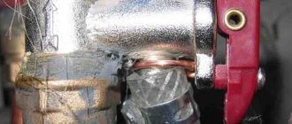
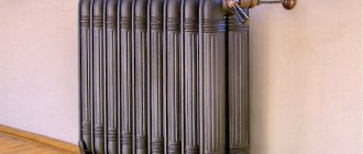
Installation location of the emergency heating valve - on the supply pipeline, near the boiler
Of all the equipment in an individual heating system, the most dangerous is the boiler. Therefore, the excess pressure relief valve is installed either directly on the boiler itself (if there is an appropriate outlet for installation) or on the supply line immediately after the boiler. The distance is small - 20-30 cm from the body. If the boiler does not have this type of fittings (indicated in the description), then it is installed in the so-called safety group or placed separately. The safety group is placed at the outlet from the supply line immediately after the boiler (before the first branch and any other device), on which a pressure gauge, automatic air vent and excess pressure relief valve are installed.
Determination of the conditional cross section and response threshold
It is easy to determine the cross-section of the emergency valve - it must be no less than the diameter of the supply pipe. Otherwise, it will not work as it should. When installing not as part of a safety group, we make the tap with a slight slope towards the boiler (it can be vertical, but definitely not in the opposite direction). If your wiring is inch, we use the same pipe to make an outlet, and install a blast valve of the same cross-section. This is understandable.
Can be part of a security group or installed separately
The response threshold is determined based on the operating pressure of the system. For normal operation it should be 20-30% higher. If your heating operates at 1.2 Bar, then the excess pressure relief valve should operate at 1.45-1.55 Bar.
It is not always possible to find an emergency valve with the required response value. You can either take one with similar parameters, or find an adjustable one (there is one for 1.5 Bar).
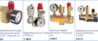
Manufacturers
The greatest demand is for security groups from Valtec and Watts. Their products are distinguished by high quality workmanship and reliability. For example, VT.460.0.0 from Valtec is used for heating systems with a nominal pressure of up to 10 bar. The maximum temperature of use should not exceed +120°C. Steam, water or a special liquid can be used as a coolant.
The emergency valve has a fixed setting of 3 bar. The body of the safety group is brass, nickel plated. The thread for connection is internal, size 1″. The cost of the VT.460.0.0 group starts from 1,700 rubles.
Security Groups from Watts
The WattsKSG-MS security group has similar characteristics. The body is made of brass, but unlike the previous device, it is located in a heat-insulating casing. The emergency valve response threshold is 3 bar.
When installing the safety group and other parts of the heating system, you must strictly follow the instructions supplied with them from the manufacturer. Because if installed incorrectly, the system will not work properly, or an error made during installation will lead to its breakdown.
In what cases does the valve usually trip?
There are four typical situations when a heating valve is triggered.
- Fluid is pumped into the system using a hand pump without pressure control, or automatic filling turns out to be defective and produces increased pressure.
- The heating system is faulty - the expansion tank was not installed or was turned off by the tap.
- The expansion tank is not working properly - there is no air in it.
- Boiler boiling with massive release of steam.
Recommendations for selection and installation
Since not all manufacturers of heating equipment complete their products with a safety group, you often have to make the choice of a safety valve for the heating system yourself. To do this, it is necessary to study the technical characteristics of the boiler installation, namely, know its thermal power and maximum coolant pressure.
For reference. Most solid fuel heat generators of well-known brands have a maximum pressure of 3 Bar. An exception is STROPUVA long-burning boilers, whose limit is 2 Bar.
The best option is to purchase a valve with pressure control that covers a certain range. The regulation limits must include the value for your boiler. Then you need to select a product according to the power of the thermal installation, but it’s difficult to make a mistake here. The manufacturer's instructions always indicate the limits of the thermal power of the units with which a valve of a particular diameter can operate.
It is strictly forbidden to install shut-off valves on the section of the pipeline from the boiler to the place where the excess pressure relief valve is installed. In addition, you cannot install the device after the circulation pump; do not forget that the latter is not able to pump the steam-water mixture.
To prevent splashing of water throughout the furnace room, it is recommended to attach a tube to the outlet of the valve that drains the discharge into the sewer. If you want to visually control the process, then you can place a special drain funnel on the vertical section of the tube with a visible break in the stream.
The act of setting
The act of setting up the safety valve is a mandatory document. It is written on each valve. The form of the act can be adjusted.
If the conditions for adjusting the device change, then entries must be made in the document. All points in the form must be filled out. If there is no separate data, they write: “ No data required .” The act also indicates the commission that accepts the readiness of the device for operation. At the end of the document, the signatures of the members of this commission are required.
Source
Types of valves
Under the influence of the pressure of the superheated coolant, the membrane rises and is discharged into the drain.
The following types of mechanisms are suitable for installation in a heating system:
Discharge
A relief valve for heating operates according to the principle of the simplest protective device: the resulting gases or coolant, after reaching the excess pressure limit, press on the membrane and leave the system.
Lever-load
Suitable for pipes with a diameter of 0.2 m and larger. In heating systems in which the heat source is a boiler, lever-load type valves are not installed. In these mechanisms, a load is used to increase the effect on the membrane. In order to determine the pressure force at which the valve is activated, adjustment is carried out by changing the mass of the load.
Back
An emergency device of this type is installed to relieve excessive pressure. Additionally, it allows the coolant to move through the pipes in only one flow, determined by the design.
Spring
In a ball valve design, the excess pressure depends on the weight and size of the ball
The most popular device is used for an autonomous heating system. The device is durable and has a simple design: the rod is pressed by a spring. It is possible to configure the device’s response parameters using the existing control mechanism. The force of impact is determined by the degree of compression.
Ball
It has a very simple design: the hole is closed with an ordinary steel ball (by weight). The valve response pressure is pre-calculated; it directly depends on the diameter of the hole and the weight of the ball.
Air
The purpose of such a valve is to free the system from the resulting gases that create plugs and prevent the heating from working properly.
Advantages and disadvantages
The relief valve has the following advantages:
- eliminates water hammer and pressure surges;
- prevent the appearance of air pockets in the liquid media transportation system;
- simple design that is easy to maintain and repair;
- relatively low cost;
- possibility of automatic control and pressure release;
- simple installation technology;
- unpretentiousness to operating conditions;
- do not require frequent maintenance.
Flaws:
- presence of operating error;
- increased wear of critical parts;
- limited service life.
Simple valve design
The main thing in a moonshine still is safety.
Quickly navigate to the article
Home brewing is gaining more and more fans. The number of amateurs and professionals is growing. But you shouldn’t lose sight of the safety of making moonshine. The pressure relief valve is designed to do just that. After all, there are enough cases when moonshine stills exploded in apartments of residential buildings. And this happens not only because of inexperience and irresponsibility, but also because of homemade low-quality devices.
The pressure relief valve prevents mechanical damage to the unit due to excess pressure. This happens by releasing excess gas. This happens automatically. In this case, the emission of steam stops when the working medium reaches an operating state.
Excess steam can occur not only due to improper operation. For example, the use of additional heat sources, incorrect assembly of the unit. Even if properly assembled and used, the operating environment may increase.
Operating principle
The pressure relief valve consists of the required components: a shut-off element and a set point. Last
Sectional Pressure Safety Valve
provides force on the sensitive element. The components for the closure body are a seat and a bolt. The simplest example for a valve is a spool.
In the simplest case, the set point can be a spring. With its help, it is configured in a certain way. The force on the spool must be such that the working medium does not pass through the seat. The adjuster is adjusted using a special screw.
When the pressure relief valve is closed, two forces act on it:
- the operating environment of the system it protects. Relatively speaking, this force is trying to open it.
- A master that prevents this opening.
When the force from the working environment increases, the spool is pressed against the seat with less force. At some point it will become zero. And that’s when the locking mechanism will begin to open. If the first force continues to increase, the relief valve will operate and the working medium will be discharged through it.
After the decrease, the power of the set point increases again. The safety relief valve closes.
Homemade or purchased devices?
Someone remembers the times when moonshine brewing equipment was made from scrap materials. And everything was made by hand or repurposed from something. Even a pressure relief valve. Today the situation has changed. Moonshine units can be purchased ready-made. So what to choose: a ready-made device or a homemade one?
If we talk about efficiency, then it will be cheaper to make it yourself. Although some parts, such as a safety relief valve or a thermometer, will have to be purchased. Well, as for safety, it’s clear: a ready-made unit produced at the factory.
The moonshine stills on the market are of very good quality. They are collapsible, so they are easy to wash. And also quite convenient to store.
But the most important thing is that their safety is given great attention. All models have a safety relief valve, which eliminates the risk of explosion
Such additional devices of a moonshine still as automatic controllers, a thermometer and a pressure relief valve make the process of preparing homemade strong alcohol absolutely safe. Their presence in the device is mandatory. It is thanks to them that control over each stage of preparation is maximum, and risks are minimal.
Types of security groups and the principle of choosing the appropriate model
A standard safety valve for a boiler may differ in design in several design features. These nuances do not change the functionality of the device, but only simplify use and maintenance. To choose the right safety unit, you need to know what safety valves for boilers are and how they differ.
Lever models
The most common type of standard safety assembly is the lever model. This mechanism can be activated manually, which is convenient when checking or draining water from the boiler tank. They do it like this:
- A horizontally located lever is installed vertically;
- direct connection to the stem activates the spring mechanism;
- the safety valve plate forcibly opens the hole and water begins to flow from the fitting.
Even if the tank is not completely emptied, a control drain is performed monthly to check the functionality of the safety unit.
The products differ in the design of the lever and the fitting for discharging water. If possible, it is better to choose a model with a flag fixed to the body. The fastening is made with a bolt that prevents children from manually opening the lever. The product has a convenient herringbone-shaped fitting with three threads, which ensures reliable fixation of the hose.
The cheaper model does not have a flag lock. You can accidentally catch the lever with your hand and unnecessary drainage of water will begin. The fitting is short, with only one threading ring. It is inconvenient to fix the hose onto such a protrusion and can tear it off under strong pressure.
Models without lever
Safety valves without a lever are the cheapest and most inconvenient option. Such models often come complete with a water heater. Experienced plumbers simply throw them away. The units operate similarly to lever models, but there is no way to manually perform a control drain or empty the boiler tank.
Models without a lever come in two versions: with a cover at the end of the body and blind. The first option is more convenient. If clogged, the cover can be unscrewed to clean the mechanism. A blind model cannot be tested for functionality and cannot be descaled. The fluid discharge fittings for both valves are short with one threaded ring.
Safety components for large water heaters
Water heaters with a storage tank volume of 100 liters or more are equipped with improved safety valves. They work in a similar way, only they are additionally equipped with a ball valve for forced drainage, as well as a pressure gauge.
Particular attention should be paid to the fluid drainage fitting. It's threaded
Reliable fastening prevents the hose from being torn off by strong pressure and eliminates the inconvenient use of the clamp.
Original models
For lovers of aesthetics and comfort, manufacturers offer original safety components. The product is equipped with a pressure gauge, chrome plated, and given an elegant shape. The products look beautiful, but their cost is high.
Difference in body markings
High-quality products must be marked on the body. The manufacturer indicates the maximum permissible pressure, as well as the direction of water movement. The second marking is an arrow. It helps to determine which side to place the part on the boiler pipe.
On cheap Chinese models there are often no markings. You can figure out the direction of the liquid without an arrow. The check valve plate must open upward in relation to the boiler pipe so that water from the water supply flows into the tank. But it’s impossible to determine the permissible pressure without markings. If the indicator does not match, the safety unit will constantly leak or will not work at all in an emergency.
Other types of valves
When they try to save money on a safety group, they try to install a blast valve designed for the heating system on the water heater. The nodes are similar in functionality, but there is one nuance. The blast valve is not capable of releasing liquid little by little. The mechanism will work when the excess pressure reaches a critical point. The blast valve can only release all the water from the tank in the event of an accident.
Separately, it is worth considering installing only a check valve. The mechanism of this unit, on the contrary, locks the water inside the tank, preventing it from draining into the pipeline. If there is excess pressure, the working plate with the rod is not able to work in the opposite direction, which will lead to rupture of the tank.
Types of safety valves
These protection elements are classified in different ways.
| Principle of operation | Shutter lift height | Shutter opening method | Spool loading method | |
| 1 | Direct action | Low lift | Proportional | Spring |
| 2 | Indirect action | Full lift | Two-stage | Lever-gas |
| 3 | Pulse |
Spring ones are the most common, used for small boiler rooms. They have a simple and reliable design and the ability to easily adjust the operating pressure in the system. Also, one of the advantages is the low cost. Lever safety devices are not particularly popular, because, basically, the model range is represented by diameters from 50 mm. They are used in the industrial sector. Pulse devices are used on steam boilers with pressures greater than 39 kgf/sq.cm (3.9 MPa). At least 2 pieces are installed on each boiler. (control and working). Low-lift ones have a valve lift height of 5% of the seat diameter, therefore they have a low throughput. The advantages include: simple design, affordable price.
Low lift and full lift
In full-lift valves, the bolt rises to a height of at least 25% of the seat diameter. They are classified as two-stage. They are characterized by high throughput, high cost and complex design.
Full-lift safety devices have a bell. Its job is to help the bolt achieve full lift. Full lifts are used mainly in systems in which the medium is compressed. Proportional ones open the valve in proportion to the increase in pressure and the volume of the discharged medium increases proportionally with the rise of the valve. These protective devices are used for water and other liquid media.
The advantages of using a proportional valve include:
- opening the shutter according to need;
- lightweight design;
- low cost;
- vibrations occur automatically.
The disadvantage of two-stage devices is self-oscillation of the shutter. The reason for this is exceeding the standard size or variable emergency flow of the medium.
Differences in Designs
The design of different safety valves may vary. Thus, most of the fittings are produced with one saddle. You can also find designs in which two saddles (and two rods with springs) are installed side by side.
Based on the ratio of the lifting height of the locking element to its diameter, the following are distinguished:
- small lift: up to 1/20;
- medium rise: up to 1/4;
- full lift: over 1/4.
The higher the degree of lift, the faster the device operates. Low-lift models are used for liquids, where it is not necessary to discharge large volumes to reduce the pressure to normal. In them, the lifting height is proportional to the pressure of the medium. Full lift is also called two-position. They have two positions: “Open” and “Closed” and are intended for:
- high pressure liquid systems;
- gases
This design allows you to quickly discharge a significant volume of gas or liquid and is used in particularly critical installations and technological complexes.
The most serious design differences are observed in the methods of applying loading force to the closure organ.
Spring valves
Most common in household systems - water heating, plumbing, heating. The spool is pressed against the seat by the force of a compressed spring. By changing the degree of pre-compression of the spring with an adjusting screw, it can be adjusted to different limit values. Many models are equipped with a lever for forced manual opening of the shutter in order to check operation from time to time. For devices operating in hazardous and hazardous environments, manual control purge is not provided. Springs, seats and chambers of devices operating in aggressive liquids and gases are coated with special anti-corrosion coatings.
The rod passing through the body is sealed with a double seal made of particularly resistant materials (special grades of rubber, fluoroplastic), which under normal conditions prevents the penetration of aggressive substances into the room.
Lever-weight valves
Such structures use the force of gravity to counteract the force of pressure. They can only be mounted in a position strictly defined by the manufacturer relative to the horizon and are not approved for use on vehicles and other moving objects. The weight of the load is transmitted through the lever to the spool rod, balancing it as long as the pressure in the pipeline is below the threshold.
To get rid of these effects, double-seat valves are used, each of which is small in size and weight. Adjustment of such devices is carried out by adding or removing part of the load placed on the lever. They are characterized by stable operating parameters and the absence of the effect of aging of springs, which reduces their elasticity.
Magnetic spring valves
Modern designs are classified as indirect-acting products. The shut-off element is actuated by a solenoid. In the normal position, the electromagnet presses it to the seat, and when the maximum pressure is reached, the automatic control switches off the voltage on the inductor. The pressure of the medium presses the spool and the valve opens.
In another design, pressing is carried out by a powerful spring, and when a threshold pressure value is reached, the control command turns on the solenoid, and it lifts the valve.
There is a design in which the solenoid both presses the spool and presses it under the influence of oppositely applied voltage. In the event of a power failure, the device continues to operate as a normal spring device.
The main advantage of magnetic devices is that there is no need for physical access to the valve to set the threshold value. The threshold can be changed in the settings of the control program depending on the current situation or the features of a given stage of the technological process.
Such designs are significantly more expensive than their mechanical counterparts, but they pay for themselves many times over in complex industrial installations with a large number of parameters and elements influencing each other.
Reasons for valve operation
After several emergency operations, the valve needs to be replaced due to the weakness of the spring.
A working safety device will never operate without a reason. Each valve actuation must be examined to determine the trigger. There may be several of them. Although they are not always serious, everyone should be checked.
- Unstable operation or failure of the heating boiler thermoregulation system. Triggers are usually frequent and water spills are abundant.
- Problems with the expansion tank. This may be the initial setup. Hidden reasons: nipple malfunction, membrane failure. In such cases, sudden pressure surges occur in the system, which leads to short and frequent valve openings.
- Limit value of pressure in the heating system. The protection mechanism leaks slightly. Such manifestations are present because the accuracy of the spring device is ±20%. To avoid such situations, you should more accurately configure the system and select the appropriate equipment.
- Valve wear. After several trips, the performance of the protective device decreases. Therefore, it is better to replace it with a new one or repair it.
- Malfunction of the spring. This happens over time, even in the absence of triggers. Sometimes drips appear as a result of coolant leaking around the rod. Under such circumstances, repair or replacement cannot be avoided either.
You can check the serviceability of the safety valve using the red handle. If you turn it in a clockwise direction, water should appear on the normal valve. The leak stops immediately after the handle stops rotating. If this does not happen, you need to twist it again. When this does not help, the protective device will need to be replaced.
Adjusting the mechanism for proper operation
The safety valve is adjusted after completion of installation work and complete flushing of the system. Spring devices can be adjusted by rotating the adjusting knob (colored plastic cap), the rotation compresses or decompresses the spring that puts pressure on the spool. In lever-load trucks, this is done by hanging a load on the lever.
It is necessary to set the set pressure, full opening and closing:
- The setting pressure should be set slightly higher than the maximum operating pressure of the boiler.
- The full opening pressure should not exceed the maximum permissible standards of the most vulnerable element of the system, usually the boiler heat exchanger, designed for 3 or 2 bar, and in some Russian models even 1.5 bar.
- The valve closing pressure must be set slightly higher than the minimum allowable for system operation.
Installation rules, replacement frequency
An emergency valve is always installed on the supply side, after the boiler. In this case, the following rules are observed:
- If the relief valve is installed separately, a pressure gauge is placed in front of it to monitor the condition of the system.
- Placed at a distance of 20-30 cm from the boiler.
- The outlet is made with a pipe of the same diameter as the supply pipeline. To determine the pressure as accurately as possible, it may have a slight slope towards the boiler.
- Shut-off devices (taps, check valves, etc.) must not be installed between the boiler and the blast valve.
- In systems with natural circulation, this device is placed at the highest point of the system.
Placed close to the boiler (in many models it is located in the boiler itself, in some boilers there is space for installation)
To prevent the discharged coolant from leaking onto the floor, you can put a hose on the outlet pipe. It can be placed in a container or discharged into the sewer. But in this case, it is necessary to somehow monitor the operation - set an alarm. After all, he doesn’t just play off, but for some reason.
Another important point: after several operations (5-6), the excess pressure relief valve must be replaced. This is due to spring wear. The device starts to work incorrectly. The valve costs a little, so it’s not expensive. The only unpleasant point is that locking devices cannot be placed in front of it. Therefore, the emergency valve can only be removed by completely stopping the system and reducing the pressure to atmospheric pressure. That's the rub.
Where to install the overpressure relief valve
The situation can be improved if shut-off valves are placed after the demolition man. In this case, at least you won’t have to drain the coolant from the system, but only from the boiler, which is not so scary.
How does a tuned relief valve work?
When the set pressure is reached, the valve opens. If the pressure continues to increase, the device opens more and reaches full opening at 10% above the set pressure.
If the valve does not have enough capacity, it will not be able to relieve pressure. This is why it is important to choose the right emergency pressure relief valve. All flow characteristics of safety valves (flow coefficients, calculated cross-sectional areas and throughput tables) must be indicated in the device passport.
Purpose of the gas valve
PSK is a safety valve element responsible for the safety of the gas pipeline and gas equipment connected to it. During operation, the valve is in a closed position, therefore it is classified as a closed pipe fitting.
Such devices are installed not only on gas pipelines, they are an integral part of other communications - water supply, heating networks. Everywhere they perform the same function - they stabilize the pressure in the network, provide the operating parameters necessary for the proper functioning of the system.
The valve serves to relieve excess gas if pressure parameters become critical. Fuel that creates an imbalance in the system is discharged into an auxiliary pipeline or discharged into the atmosphere
The pressure surge is usually short-lived and depends on a number of factors.
Reasons that can cause excess pressure in the system:
- breakdown of connected gas equipment - double-circuit boiler, instantaneous water heater or capacitive boiler, shut-off valves;
- use of fuel of inappropriate composition;
- change in temperature indicators in the pipeline;
- failure in the thermal-mechanical circuit.
The installation location of the gas safety valve is standard, depending on the efficiency of the application: either in the pressure regulator, or immediately behind it. After automatic operation of the valve, it returns to its operating – closed state.
In a gas network, the valve is a separate device or integrated into the pressure regulator. It is triggered if the operating gas pressure exceeds the nominal level by 15%
What are the consequences of the absence of a PSK on the network? The most common consequences are mechanical destruction of the pipeline or breakdown of connected equipment, which can cause a gas leak.
There is also a possibility of an explosion, so it is necessary to constantly monitor the serviceability of the device, carry out timely maintenance and replace failed elements
Along with relief devices, gas safety shut-off valves are also used, with the help of which the fuel supply is shut off. This happens automatically. The shut-off valve element is installed on the pipeline, in the gap between the filter and the pressure regulator.
The operating limit of the SPD is indicated in the technical data sheet of the device. The upper critical parameter is usually equal to the formula: slave. pressure +25%.
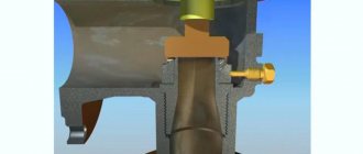
Design and principle of operation of the valve
Valve design
Safety valve design:
- protective cover;
- outlet;
- fillings;
- compression springs;
- cone;
- saddles;
- pressure chamber.
The body is made using hot stamping technology, usually brass is used, and therefore has a long service life. The control unit is made of heat-resistant plastic and does not change its shape. There are different types of safety valves, but the principle of operation is the same. The saddle is acted upon by a spring mechanism and is in the closed state. If the pressure in the pipeline is stronger than the force of the compression spring, the seat will open and the coolant will be released.
Professional installation advice
Even such a simple procedure as installing shut-off valves is based on the implementation of certain rules. For example, the design of a room often requires camouflage of the pipeline and security group.
You can hide devices, but subject to three conditions:
- the length of the flexible line or pipe from the fuse to the tank should not exceed 2 m, otherwise there will be excessive additional pressure on the valve spring;
- the ideal installation of the fuse is directly to the boiler fitting, and if this does not work, then installing a tee is still excluded;
- To service the fittings, a technical hatch should be equipped.
Many people worry when they see drops of water on the valve connection. This is a normal phenomenon and indicates that the device is working properly.
From time to time, small pressure surges occur in the line, which provoke a minimal discharge of liquid. You need to worry when water either does not appear at all or pours continuously.
The line length between the water heater and the fuse should be minimal. This is necessary not for aesthetic reasons, but so as not to create additional pressure in the pipes
It should be remembered that independent modernization of safety devices is strictly prohibited. If you need a 0.8 MPa valve, then you need to purchase just such a new product, and not try to somehow remake or adjust the 0.7 MPa device.
If there is any doubt about the functionality of the safety valve, you should dismantle it and check whether the spring or seal is clogged. Are you having problems with your water heater itself and don’t know what to do? We recommend that you familiarize yourself with common boiler breakdowns and repairs. If you lack skills, invite a specialist from the service center.
Installation diagram of the device on the boiler
There are few requirements for correct installation of the valve device:
- The safety valve is always installed in the gap in the cold water line between the shut-off valve and the inlet to the boiler; no other devices should be placed in this gap;
- The maximum distance from the inlet pipe on the boiler to the valve fuse is 180-220 cm;
- For most models, the device is installed vertically, with water flowing from bottom to top. The direction of movement of the water flow is indicated by an arrow on the body.
The drain fitting on the safety valve must be connected by a transparent PVC pipe to the sewer line. The transparent tube is very convenient to use - you can clearly see how the safety valve works.
In order not to drill or cut the sewer pipe, you can use a special tee for washing machines, as in the video
Before installation, the body is carefully purged with air to avoid a loose fit of the plate to the seat due to debris or scraps of packing tape accidentally getting inside. The valve is assembled according to the traditional scheme - the threads are wound up with a hammer in the direction of tightening the union nut and twisted with the inlet or underwater hoses.
Before starting the boiler, the cold connection is pressurized under operating pressure. If no water droplets appear at the joints within 5-7 minutes, it means the installation was completed correctly.
After filling the boiler, it is necessary to check the operation of the safety and check valves. The test is carried out “cold”. The correct adjustment of the emergency water discharge can be checked with a flag. With a slight pressure, about 1/5 of the full stroke, the first drops should appear, and with full pressure the water runs in a stream. This means that the factory settings are correct.
The operation of the check valve can be checked as follows. It is necessary to fill the boiler completely, then close the shut-off valve at the entrance to the tank and the central inlet. When you open the tap in the bathroom and kitchen, water will run out of the pipes for the first couple of minutes. If the flow does not stop even after 5 minutes, it means that the “return” does not hold and requires adjustment. The flow of water from the boiler can be indirectly monitored by the pressure drop on the pressure gauge.
Only dismountable valve models can be adjusted directly. For this, special thin metal washers with a thickness of 0.2-0.3 mm are used. They are placed under sagging springs, and thereby the elasticity of the part is experimentally selected. Non-separable valves are replaced with new ones.
Safety valve
The name of the device speaks for itself. Its main function is to relieve unexpected loads that may arise under certain circumstances. Plus additionally adjustable coolant flow.
By the way, it can be installed on any section of the pipeline
In this case, it is not the location that is important, but the ease of maintenance if such a need suddenly arises
Types of safety valves
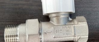
- The simplest option is clutch fuses made of brass. Their design is simple - threads are cut on both sides, and the valve is a spring-loaded rod with an EPDM gasket. This is a direct-flow model, the valve of which opens under the pressure of the coolant flow. Back pressure is blocking the line. This is one of the cheapest devices, but it lasts a very long time, which is time-tested.
- There is another brass option, but with a more complex design, where the pipes are connected in perpendicular planes. It uses a stainless steel rod and spring. Install it directly after the circulation pump. The operating principle of such a device is quite simple. The coolant pressure compresses the spring, which begins to put pressure on the rod. It opens a channel through which the coolant is squeezed out of the system, saving it from ruptures of pipes and other elements. By the way, the maximum temperature that the valve can withstand is 120C.
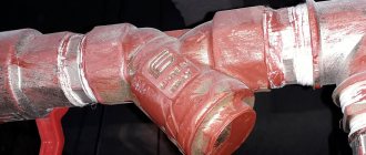
- There are a large number of varieties of check valves, which are also included in the safety group. Their main function is to prevent a counterflow of coolant from occurring if the pressure in the system suddenly drops.
There are several main types - disk, ball, flag and others. But they are all divided into spring-loaded and springless. With the first, everything is clear - there the main emphasis is on the counterforce of the spring. The second type is when the locking element returns under the influence of its own mass.
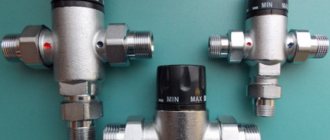
Three way valves. This type of shut-off valve is installed in heating systems where low-temperature circuits are provided. For example, when the circuit has a condensing boiler. Currently, manufacturers produce this type of valve with manual switching or electric switching. In the second case, it is necessary to connect the device to an alternating current network with a voltage of 220 volts.
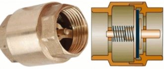
Peripheral secondary part
A check valve is an element of the heating system, consisting of a plastic or metal base, which performs the function of completely shutting off the coolant supply. This happens when the flow begins to move in the opposite direction. The metal disk is attached to a spring, which is under pressure when the flow moves in one direction, and when it moves in the opposite direction, the spring is activated to block the passage in the pipe. The valve device has not only a disk and a spring, but also a sealing gasket. This component helps keep the disc in place tightly. Because of this, there is practically no possibility of pipe leakage. Butterfly valves are widely used in domestic heating systems.
Let's look at the principle of operation and an example of when check valves are needed and when they are not. In the operating mode of circuits where there is circulation, the presence of a valve is not necessary. For example, if you look at a classic boiler room, where there are three parallel circuits. This can be a radiator circuit with a pump, a heated floor circuit with its own pump, and a boiler loading circuit. Often such schemes are used when working with floor-standing boilers, which are called pump priority schemes.
Pumping priorities are the determination of alternating operation of pumps. For example, the use of check valves occurs when only one pump remains in operation.
The installation of valves is completely unnecessary if there is a hydraulic arrow on the diagram. This allows, during pressure drops in certain pumps, to get rid of this problem without using check valves. The hydraulic arrow indicates the closing section, which works to restore pressure in one of the pumps.
The presence of a floor-standing boiler in the circuit also makes it possible not to install check valves for heating. This occurs due to its barrel, which bridges a certain place from the drop, which is considered to be zero resistance or a hydraulic arrow. The capacity of such barrels sometimes reaches 50 liters.
Check valves in heating are used if the boiler is placed at a sufficiently large distance from the pumps. In addition, if the components and the boiler are 5 meters apart, but the pipes are too narrow, this creates losses. In this case, a non-working pump can create circulation and pressure on other components, so it is worth installing a check valve on all three circuits.
Another example of using check valves is when there is a wall-mounted boiler, and two units are operating in parallel with it. Most often, wall-mounted boilers have one radiator system, and the second is a wall-mounted mixing module, along with a heated floor. Check valves do not need to be installed; if the mixing unit operates only in constant mode, then when not in operation the valves will have nothing to regulate, because this circuit will be closed.
There are times when the pump on the mixing wall unit does not work. This sometimes happens when the room thermostat pump turns off during a certain room temperature. In this case, a valve is necessary because circulation will continue in the node.
Nowadays, modern mixing units are offered on the market, when all loops on the collector are turned off. To prevent the pump from idling, a bypass with a bypass valve is also added to the manifold. They also use a power switch that turns off the pump when all loops on the manifold are closed. The absence of the proper elements can cause a short-circuited unit.
These are all cases where check valves are not needed. In most other conditions, check valves are not required. Valves are used only in a couple of cases:
- When there are three parallel connection nodes and there is no work in one of them.
- When installing modern collectors.
There are very few cases where check valves are used, so now they are gradually being removed from use.