A person physically cannot stay in the boiler room all the time to monitor the health of the heating line, temperature readings and pressure level of the heating device. The main assistants in this matter are additional devices that automatically monitor the functioning of the system.
We will tell you what devices the heating safety group includes, how they operate, and how they protect the system. Taking into account our advice, you can easily select the necessary components. The article describes the rules for assembling and connecting this important link, which is responsible for trouble-free operation.
Trigger algorithm
Let us briefly summarize the principle of operation of the entire group. From the very beginning of commissioning, an automatic air vent operates, removing all air from the system. However, if it overheats and reaches critical pressure levels, it is powerless. To avoid an emergency, the safety valve is activated, releasing excess coolant, thereby reducing the pressure in the system.
To monitor the operation of the system, the safety group includes a pressure gauge that shows the pressure at the moment: low pressure indicates depressurization, a malfunction of the expansion tank or make-up valve; increased - about expansion of the coolant or excessive release of steam due to overheating.
Water heater protection
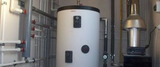
Indirect heating boilers and electrical storage devices that prepare water for household needs also require protection. In this case, the danger is represented by pressure surges in the water supply and expansion of the liquid in the tank due to heating. To prevent the tank from leaking, a boiler safety group is installed at the water supply, consisting of the following parts:
- brass body;
- a check valve that does not allow water to flow from the container back into the pipe;
- safety valve that relieves excess pressure;
- ball valve to close the hot water supply line.
Storage water heater safety group from the VALTEC brand
In addition, indirect heating boilers are equipped with an automatic air vent mounted in the upper part of the tank and a dial temperature meter. A pressure gauge is optionally installed on the unit.
What does a heating system safety group consist of?
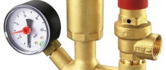
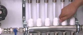
The safety group for the heating system consists of a housing on which three devices are installed: a pressure gauge, a safety valve and an automatic air vent:
Safety group for heating: from left to right - safety valve, automatic air vent, pressure gauge
Let's consider these devices each separately.
Safety valve
The purpose of the safety valve is to protect the heating system from too much pressure.
The safety valve is designed for a certain pressure and when this pressure is exceeded, it is activated, i.e. it releases excess.
In fact, the expansion tank is responsible for compensating for excess pressure in the heating system: water expands when heated - its excess is forced into the expansion tank, which keeps the pressure in the system constant and the system intact. At the same time, the total amount of coolant in the entire heating system remains the same.
But it happens that for some reason the expansion tank did not work. For such a nuisance, a safety valve is installed through which excess water will be discharged from the system. To prevent water from flowing out onto the floor, we attach a tube to the thread on the side and lead this tube into the sewer.
Conclusion: sewerage in the boiler room is very desirable.
And further:
important! Antifreeze must not be disposed of down the drain!
On top of the safety valve there is a handle (red, similar to a water tap valve). Using this handle we check the operation of the safety valve. The functionality of the valve is checked very simply: turn the handle in the direction indicated by the arrow - water flows, release the handle - it stops flowing, which means the valve is working, we can sleep peacefully. If the water continues to leak, open and close it a second time, a third time... usually the flow stops.
But if the valve stubbornly does not hold water, you will have to replace it. And the faster, the better, because its performance is important.
The coolant may leak through the safety valve due to the valve not fitting tightly into the seat (for the uninitiated it sounds like nonsense, but it is true).
They produce safety valves designed for different pressures; you need to select them based on the pressure for which our boiler is designed. For the heating system of a private house, we buy a 3 atm valve.
Let's say there is no safety group with the required valve on sale. Then we buy the listed devices separately and assemble the security unit with our own hands.
Pressure gauge
A pressure gauge is a device for monitoring pressure in a heating system.
Like safety valves, there are pressure gauges designed for different pressures; you need to select one that is convenient to use: one glance at the device should be enough to determine its readings, without any calculations.
Conclusion: since the pressure in the heating system of a private house should be between 2 and 3 atm, then select a pressure gauge no more than 4 atm:
The pressure gauge has two arrows: red – control, black – working. The red one is set manually to the desired level (usually 2 atm, for floor-standing boilers it is no longer recommended, but in general, we check in the boiler passport). If during heating operation the working arrow deviates further than red - alarm! Something has “flyed”!
Automatic air vent
The entire safety group is placed on top of the boiler because of the air vent: it should be at the highest point where air bubbles rush.
Read more about this device in the article about the purpose, design and installation of an automatic air vent.
Equipment selection rules
For each model of the protective block, the accompanying documentation specifies the parameters for which it is designed.
The main criteria influencing the choice of device:
- thermal characteristics of the boiler for which the unit is designed, kW;
- maximum coolant temperature, °C;
- nominal pressure;
- compatibility with coolant - water, steam or antifreeze;
- diameter of the connecting thread - if there is a mismatch, it will be enough to purchase adapters of the required diameter.
Correct selection of the power of the safety unit ensures reliable protection of the boiler from any malfunctions in the operation of the heating circuit.
How to connect a solid fuel boiler
The canonical connection diagram for a solid fuel boiler contains two main elements that allow it to function reliably in the heating system of a private home. This is a safety group and a mixing unit based on a three-way valve with a thermal head and a temperature sensor, shown in the figure:
The always open output of the mixing valve (the left pipe in the diagram) must be directed to the pump and heat generator, otherwise there will be no circulation in the small boiler circuit
The presented diagram shows how to connect the unit correctly and is used with any solid fuel boilers, including pellet ones. You can find various general heating schemes - with a heat accumulator, an indirect heating boiler or a hydraulic arrow, in which this unit is not shown, but it must be there. The method of protecting against moisture loss in the firebox is discussed in detail in the video:
The task of the safety group, installed directly at the outlet of the supply pipe of a solid fuel boiler, is to automatically relieve pressure in the network when it rises above a set value (usually 3 Bar). This is done by a safety valve, and in addition to it, the element is equipped with an automatic air vent and a pressure gauge. The first releases the air appearing in the coolant, the second serves to control the pressure.
How the scheme works
The mixing unit, which protects the heat generator from condensation and temperature changes, operates according to the following algorithm, starting from kindling:
- The firewood is just starting to burn, the pump is on, the valve on the side of the heating system is closed. The coolant circulates in a small circle through the bypass.
- When the temperature in the return pipeline rises to 50-55 °C, where the attached remote-type sensor is located, the thermal head, at its command, begins to press the three-way valve stem.
- The valve slowly opens and cold water gradually enters the boiler, mixing with hot water from the bypass.
- As all the radiators warm up, the overall temperature increases and then the valve closes the bypass completely, passing all the coolant through the heat exchanger of the unit.
This piping scheme is the simplest and most reliable; you can easily install it yourself and thus ensure the safe operation of the solid fuel boiler. There are a couple of recommendations regarding this, especially when piping a wood-burning heater in a private house with polypropylene or other polymer pipes:
- Make the section of the pipe from the boiler to the safety group from metal, and then lay plastic.
- Thick-walled polypropylene conducts heat poorly, which is why the surface-mounted sensor will openly lie, and the three-way valve will lag. For correct operation of the unit, the area between the pump and the heat generator, where the copper flask is located, must also be metal.
Connecting with copper pipes will not protect polypropylene from destruction in the event of overheating of the TT boiler. But it will allow the temperature sensor and safety valve on the safety group to work correctly
Another point is the installation location of the circulation pump. It is best for him to stand where he is shown in the diagram - on the return line in front of the wood-burning boiler. In general, you can install the pump on the supply side, but remember what was said above: in an emergency, steam may appear in the supply pipe.
The pump is unable to pump gases, so when the chamber is filled with steam, the impeller will stop and the coolant circulation will stop. This will speed up a possible explosion of the boiler, because it will not be cooled by water flowing from the return.
Way to reduce the cost of strapping
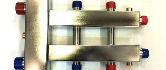
The condensate protection circuit can be reduced in cost by installing a three-way mixing valve of a simplified design that does not require connecting an overhead temperature sensor and thermal head. It already has a thermostatic element installed, set to a fixed mixture temperature of 55 or 60 °C, as shown in the figure:
Special 3-way valve for solid fuel heating units HERZ-Teplomix
Installing such an element definitely allows you to save on piping the TT boiler. But in this case, the possibility of changing the temperature of the coolant using a thermal head is lost, and its deviation at the output can reach 1-2 °C. In most cases, these shortcomings are insignificant.
Radiator control and shut-off valves
Heating radiators are equipped with half-turn ball valves, which allow you to completely shut off or, conversely, open the coolant supply to the radiator. Taps are placed at the entrance to the device. Sometimes thermostatic radiator valves (without presetting) are used instead, which automatically shut off the coolant supply when the room temperature exceeds the set values.
The listed devices cannot be used to balance the system. Balancing valves (valves) and thermostatic valves with presetting serve these purposes.
How and where to install the expansion tank
So, we are going to design and assemble a heating system with our own hands. If it also starts working, our joy will know no bounds. Are there instructions for installing the expansion tank?
Open system
In this case, the answer will be prompted by simple common sense.
An open heating system is, in essence, one large vessel of complex shape with specific convection currents in it.
The installation of a boiler and heating devices in it, as well as the installation of pipelines, must ensure two things:
- Rapid rise of water heated by the boiler to the top point of the heating system and its drainage through the heating devices by gravity;
- Unhindered movement of air bubbles to where they will rush in any vessel with any liquid. Up.
The conclusions are obvious:
- The installation of a heating expansion tank in an open system is always carried out at its highest point. Most often - at the top of the accelerating manifold of a single-pipe system. In the case of top-fill houses (although you hardly have to design them) - at the top filling point in the attic.
- The tank itself for an open system does not need shut-off valves, a rubber membrane, or even a lid (except to protect it from debris). This is a simple water tank open at the top, into which you can always add a bucket of water to replace the evaporated water. The price of such a product is equal to the cost of several welding electrodes and a square meter of steel sheet 3-4 millimeters thick.
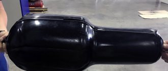
This is what an expansion tank for an open heating system looks like. If desired, a water tap from the water supply can be brought into the hatch in it. But much more often, as the water evaporates, it is topped up with an ordinary bucket.
Closed system
Here both the choice of tank and its installation will have to be taken quite seriously.
Let's collect and systematize the basic information available on thematic resources.
Installation of the expansion tank of the heating system is optimal in the place where the water flow is closest to laminar, where there is a minimum of turbulence in the heating system. The most obvious solution is to place it in the direct filling area in front of the circulation pump. In this case, the height relative to the floor or boiler does not matter: the purpose of the tank is to compensate for thermal expansion and dampen water hammer, and we can bleed the air through the air valves.
Typical tank installation diagram. Its location in a single-pipe system will be the same - in front of the pump along the flow of water.
- Factory equipped tanks are sometimes equipped with a safety valve that relieves excess pressure. However, it is better to play it safe and make sure that your product has it. If not, buy one and install it next to the tank.
- Electric and gas boilers with electronic thermostats are often supplied with a built-in circulation pump and heating expansion tank. Before you go shopping, make sure you need them.
- The fundamental difference between membrane expansion tanks and those used in open systems is their orientation in space. Ideally, the coolant should enter the tank from above. This subtlety of installation is designed to completely remove air from the compartment of the tank that is intended for liquid.
- The minimum volume of the expansion tank for a water heating system is taken approximately equal to 1/10 of the volume of coolant in the system. More is acceptable. Less is dangerous. The volume of water in the heating system can be roughly calculated based on the thermal power of the boiler: as a rule, 15 liters of coolant per kilowatt is taken.
- A pressure gauge mounted next to the expansion tank and the feed valve (connecting the heating to the water supply) can provide you with an invaluable service. The situation with a stuck safety valve spool, alas, is not so rare.
- If the valve releases pressure too often, this is a clear sign that you have miscalculated the volume of the expansion tank. There is no need to change it at all. It is enough to purchase another one and connect it in parallel.
- Water has a relatively low coefficient of thermal expansion. If you switch from it to a non-freezing coolant (for example, ethylene glycol), you will again need to increase the volume of the expansion tank or install an additional one.
The expansion tank in the photo is installed according to all the rules: the coolant is supplied from above, the tank is equipped with a pressure gauge and a safety valve.
Prices: summary table
| Manufacturer and model | Maximum CO power, kW | Response pressure, bar | Thread diameter, inch | price, rub. |
| TIM JH-1024-1.5 | 50 | 1,5 | 1″ BP | 990-1 200 |
| VALTEC VT.460.0 | 44 | 3 | 1″ BP | 1 650-1 800 |
| Watts KSG 30 | 50 | 3 | 1″ BP | 2 600-3 400 |
| Caleffi 302631 | 50 | 3 | 1″ BP | 4 500-4 750 |
Connection diagram
A floor-standing boiler, unlike a wall-mounted one, does not have a built-in circular pump, an expansion chamber or a safety group. All this needs to be installed outside it. The supply pipe is connected to the top of the boiler and the safety group is mounted there.
Correct installation of the safety group, where it is located at a distance from the crane and does not interfere with it
There should be no shut-off valves, filters or other elements between the boiler and the safety group. For example, if the tap is closed, an accident will occur.
Note! The safety group is always mounted only in a vertical position and above the boiler. The security group can be presented in a corporate form
The main element in it is an emergency valve that relieves pressure. In some cases, instead of the entire safety group, it is possible to install only one emergency valve on the tee
The security group can be presented in a corporate form. The main element in it is an emergency valve that relieves pressure. In some cases, it is possible to install only one emergency valve on the tee instead of the entire safety group.
Very often, a safety group is placed immediately above the boiler, and at the moment the pressure is released by the valve, liquid enters the boiler, which is unacceptable if it is electric. Therefore, if the safety group is installed above the boiler, then a tube is connected to the emergency valve and taken to the side. A container for liquid is placed under it.
Connection diagram for a safety group in a heating system with an expansion tank
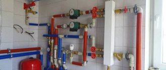
The return circuit is carried out as follows (in the direction from the boiler) - a shut-off valve, a circulation pump, a dirt filter, a second shut-off valve, a tee with a valve for connecting the expansion tank and a valve for filling the network. For systems with such a simple circuit, installation of a check valve is not required. The dirt filter is mounted with an oblique outlet downwards. The pump rotor must be horizontal and the terminal box in the upper position.
Note! The expansion chamber must not be installed in front of the first shut-off valve. Expanzomat compensates for pressure fluctuations in the heating system
When water heats up, it expands. To prevent pressure from being released through the emergency valve, the expansion tank reduces it. The volume of the expansion chamber must be at least 1/10 of the entire system
The expansion valve compensates for pressure fluctuations in the heating system. When water heats up, it expands. To prevent pressure from being released through the emergency valve, the expansion tank reduces it. The volume of the expansion chamber must be at least 1/10 of the entire system.
For example, if the boiler volume is 80 l, and the heating system is 140 l, then the total volume is 220 l. Therefore, an expansion tank of 22 liters is required for stable operation. Experts recommend taking a larger expansomat - 1/7-1/8 of the volume of the entire system.
Expansion tank in a closed heating system
As a sealant for threaded connections, it is recommended to use FUM tape, flax, pastes or other sealing agents that will ensure a tight connection of all elements even during heavy loads.
Rating of popular models
Among the manufacturing companies involved in the development of safety valves, the following popular companies can be distinguished: Watts and Valtec. The manufacturer Watts is famous for its fairly extensive range of devices for the heating system, among which the safety unit occupies an important place.
The KSG series has various threaded body devices, differing in their sizes (from standard to compact) and material of manufacture:
- cast iron;
- steel;
- brass.
Additionally, some models come complete with heat-insulating casings. Units from the KSG line are typically equipped with a relief valve designed for a critical pressure of 3 bar. Installation into the heating main is carried out using a 1-inch diameter connector with internal thread.
The KSG model range from Watts, designed for operation in a boiler room with heat generators with a capacity of 50-200 kW
Valtec is not inferior in quality to its products to the previous brand. The company presents a line of devices for boilers and expansion tanks - the VT 460 and VT 495 series, respectively.
The VT 460 model range is designed to operate with domestic heating units with a power of up to 44 kW, at a maximum pressure of 3 bar. However, the prices for ready-made devices are far from cheap, so the solution of self-assembly of such a unit can be called advisable.
Valtec develops protective blocks designed for all types of heat generators. A characteristic feature of the VT 460 series is the packaging of safety group modules in a compact brass housing
Where is the expansion tank installed for heating?
So, the installation of the tank depends on the type of heating system and the purpose of the tank itself. The question is not why an expansion tank is needed, but where it should compensate for the expansion of water. That is, in the heating network of a private house there may be not one such vessel, but several. Here is a list of functions assigned to various expansion tanks:
- compensation of thermal expansion of water in closed heating systems;
- in open networks, the reservoir performs 2 functions - it absorbs excess coolant volume and removes air from the system into the atmosphere;
- under certain conditions, the membrane tank serves as an addition to the standard expansion tank of the gas boiler;
- absorb excess heated water in the hot water supply network.
Being at the highest point of an open type system, the tank acts as an air vent
In open heating networks, the water in the reservoir comes into contact with atmospheric air. Therefore, the installation of the expansion tank is provided at the highest point - on the riser coming from the boiler. Often these systems are made gravity, with increased diameters of pipelines and a large amount of coolant. The capacity of the tank should be appropriate and be about 10% of the total volume of water. Where else if not in the attic to put such a large tank?
Alternative homemade open tanks made from a plastic canister (photo on the left) and an air receiver
Closed-type heating systems are distinguished by the fact that the membrane expansion tank for water is completely sealed. The optimal installation option is in the boiler room, next to other equipment. Another place where it is sometimes necessary to install a closed expansion tank for heating is the kitchen in a small house, since the boiler is located there.
In closed systems operating on non-freezing coolant, the volume of the tank should be increased to 15% of the total amount of liquid. The reason is the increased coefficient of thermal expansion of glycol antifreeze.
Balancing according to design calculations
The easiest way is to balance the system using the data specified in the heating project. The essence of balancing, regardless of the chosen method, comes down to setting the required coolant flow in various parts of the system. The flow is regulated using balancing valves or thermostatic valves with presetting.
The balancing valve has its own gradation. In this case, the different positions of the control valve correspond to a certain volume of coolant that is capable of passing through the device per unit time at a given pressure.
If you have a project for a heating system, you can properly balance it quite simply: by setting the coolant flow rate in accordance with existing calculations.
Evgeniy Kruchinin
But it is important to take into account the fact that often design calculations differ from the actual parameters of the heating system. For example, the hydraulic resistance of a heating circuit can be easily changed by adding or removing an element from the system. But, in general, a good and correct project is a rarity for private houses.
Therefore, even if there is a project, the balancing methods presented below do not lose their relevance.
Principle of operation
Each heating system has its own specific maximum pressure values. This is directly affected by the degree of heating and cooling of the liquid that is in the network. As described above, due to the fact that the pressure begins to exceed the norm, significant damage can occur. To understand how the safety unit helps to avoid the consequences of emergency situations, it is worth considering the principle of its operation.
The set of parts of the safety unit may vary depending on the purpose for which the main unit is used, but in the basic configuration the system contains only three modules that are built into the housing. This is a pressure gauge, an air vent (Maevsky tap) and a safety valve.
Let us examine in more detail the purpose of all three elements.
A pressure gauge is a measuring device that can be used to quickly monitor pressure readings. Its most important function is to determine the most accurate data. But, like any device, it has certain errors. The measuring units in pressure gauges are either bars or atmospheres, but the first option remains the most popular.
As can be understood from the descriptions, each part of the security unit performs its own specific functions. The elements can either be located separately, in different parts of the pipeline, or be in a single bundle. There is also another option for completing the system. It has a hydraulic shock absorber added to it, protecting the pressure gauge from the effects of the environment.
The equipment as a whole operates according to a certain simple scheme. If for some reason the expansion tank cannot compensate for the expansion of the coolant, and the closed system is subjected to high pressure, then the pressure in the bowels of the equipment also increases. At this moment, the safety valve comes into operation. Its spring compresses and the valve opens. This way, the excess coolant gets the opportunity to escape, the excess air exits through the air vent.
This is due to the fact that in such systems there is often too little draft inside the chimney. In the pipeline itself, the pressure can also become either too low or too high. Due to such problems, gas contamination of the room is possible.
Choice
It is important to select a safety group that exactly matches the characteristics of the assembled heating system. Each element of the group, pressure gauge, safety valve and air vent has its own technical and operational characteristics, which must exactly meet the requirements of the heating project
Manufacturers offer ready-made solutions and safety group assemblies based on the most common home heating options, for various boilers and wiring methods.
Before you make your choice, you should carefully read the technical manual for your boiler. If it is a wall-mounted gas or electric boiler, then it already has a safety group, which is fully consistent with its parameters, so there is no need to duplicate it. In the case of floor-standing boilers, solid fuels, stoves and fireplaces with a water circuit, in most cases there is no built-in equipment or piping. Read about how to choose a heating boiler here.
All elements of a security group are pinned to a single console. This is actually a pipe with prepared triplets for connecting equipment and two outlets for inclusion in the heating circuit.
When choosing, you should clarify:
- Diameter for connection pipes (1', ¾', ½').
- Connection option (corner, bottom, side, etc.), from which side the pipes should be brought to the safety group, and how exactly to orient it.
In any case, the air vent is mounted at the top point of the group. So it should remain connected. Below it there is a pressure gauge and a safety valve. This is done to ensure that air accumulating in the air chamber does not affect the pressure gauge readings and the operation of the explosion valve.
Material for the manufacture of the safety console: nickel, stainless steel, bronze, cast iron.
Cast iron is used only for high-pressure and efficient heating systems with a large cross-section of pipes in the distribution. These are mainly collective industrial boiler houses. For a private home, it is better to choose nickel or stainless steel. In this case, the console and equipment can simply be covered with an outer casing made of black cast iron for additional protection.
Pressure gauge
Two main characteristics:
- permissible measurement range (upper and lower limit);
- accuracy of measurement and indication of readings (scale and error).
The measurement range must cover, with a margin of 0.5-1 bar, the nominal pressure in the system and permissible deviations during operation.
Let’s say that the nominal pressure for heating is 3 atm. The permissible deviation downward will be equal to 1.5 atmospheres. A decrease below 1.5 atm will be considered a signal for an emergency. The upper limit will be 4.5-5 atm, after which the safety valve should inevitably operate. Accordingly, the pressure gauge range should be from 1 to 5-6 atm. It is desirable that the scale be as accurate as possible and indicate areas of attention. In this case, the scale is divided conditionally into 3-4 zones, marked with color markers, so that even with a quick glance you can react to any deviations.
Air vent
Characterized by the operating pressure in the system and response parameters. Almost all automatic valves are adjustable to set the optimal pressure and response conditions. If you set the adjustment knob to the minimum position, then at the slightest accumulation of air the valve will operate. At the maximum setting, the valve operates less frequently, but at the same time accumulates more air. It is difficult to say which installation would be more appropriate. It is easier to leave the factory settings unchanged if the heating system is installed independently.
Safety valve
The main parameter of the valve is the response pressure. The upper pressure limit in the circuit, upon reaching which the valve opens and releases part of the coolant. It is based on this characteristic that you should choose a security group first. The response pressure can be adjusted only within small limits.
It is useful to clarify in advance how to install the safety group and determine how and in which direction the valve discharges water. The discharge fitting should be oriented away from the main equipment and the heating boiler. It is necessary to select a hose for draining into the sewer.
How to tie solid fuel boilers
The connection diagram for a wood-burning heat generator is designed to solve 3 problems (in addition to supplying the batteries with coolant):
- Preventing overheating and boiling of the TT boiler.
- Protection against cold “return” and excessive release of condensate inside the firebox.
- Work with maximum efficiency, that is, in full combustion mode and high heat transfer.
The presented wiring diagram for a solid fuel boiler with a three-way mixing valve allows you to protect yourself from condensation in the firebox and bring the heat generator to maximum efficiency mode. How it works:
- While the system and heater are not warmed up, the pump drives water through the small boiler circuit, since the three-way valve is closed on the radiator side.
- When the coolant heats up to 55-60 degrees, the valve set to the specified temperature begins to mix in water from the cold “return”. The heating system of a country house is gradually warming up.
- When the maximum temperature is reached, the valve completely closes the bypass, all water from the TT boiler goes into the system.
- A pump installed on the return line pumps water through the jacket of the unit, preventing the latter from overheating and boiling. If you put the pump on supply, the chamber with the impeller can fill with steam, pumping will stop and the boiler is guaranteed to boil.
The principle of heating using a three-way valve is used for piping any solid fuel heat generators - pyrolysis, pellet, direct and long-term combustion. The exception is gravity distribution, where the water moves too slowly and does not provoke condensation. The valve will create high hydraulic resistance, preventing gravity flow.
If the manufacturer has equipped the solid fuel unit with a water circuit, the coil can be used for emergency cooling in case of overheating. Please note: the fuse on the safety group is triggered by pressure, not temperature, and therefore is not always able to protect the boiler.
A proven solution is to connect the DHW coil to the water supply through a special thermal relief valve, as shown in the diagram. The element will be triggered by a temperature sensor and at the right moment will pass a large volume of cold water through the heat exchanger.
Using the Buffer Capacity
The best way to increase the efficiency of a TT boiler is to connect it to heating through a buffer tank. At the inlet of the heat accumulator we assemble a proven circuit with a three-way mixer, at the outlet we install a second valve that maintains the required temperature in the batteries. Circulation in the heating network is ensured by a second pump.
A balancing valve on the return line is needed to adjust the performance of the pumps
What we gain thanks to the thermal accumulator:
- the boiler burns at maximum and reaches the declared efficiency, fuel is used efficiently;
- the likelihood of overheating is sharply reduced since the unit dumps excess heat into a buffer tank;
- the heat accumulator plays the role of a hydraulic arrow; several heating branches can be connected to the tank, for example, radiators of the 1st and 2nd floors, floor heating circuits;
- a fully heated tank maintains the operation of the system for a long time when the wood in the boiler firebox has burned out.
TT boiler and storage water heater
In order to load an “indirect” boiler using a wood heat generator, you need to embed the latter into the boiler circuit, as shown in the picture. Let us explain the functions of individual elements of the circuit:
- check valves prevent the coolant from flowing in the other direction along the circuits;
- the second pump (it is enough to take a low-power model 25/40) provides circulation through the spiral heat exchanger of the water heater;
- the thermostat turns off this pump when the boiler reaches the set temperature;
- An additional air vent prevents the supply line from becoming aired, which will be above the standard safety group.
In a similar way, you can connect the boiler to any boiler that is not equipped with an electronic control unit.
Date: September 25, 2022
Summarizing
You can regulate heating radiators using several types of devices, but experts believe that the best solution is to use special control valves. Such products are manual taps and automated products - thermostats, and only in some cases can a three-way valve with a thermal head be used.
In high-rise apartments with centralized heating, it is better to give preference to control taps or a three-way valve. As for individual heating systems, the problem of how to reduce the temperature of the coolant in a heating radiator is solved using thermostats.
If the apartment owner still prefers automatic adjustment of radiators, then a filter should be installed before the thermostat - it will trap most of the various impurities.
Self-assembly
There should be no difficulties during the manufacture of the security unit. To start the process, you need to prepare the following tools and materials:
- pressure gauge;
- relief valve;
- wrench and gas wrench;
- air vent;
- two squares;
- crosspiece;
- union;
- sanitary linen;
- sealant;
- adapters.
The angles are screwed into the cross. For a tight connection, plumbing flax is wound onto the thread, evenly distributing it over the surface. A small layer of sealant must be applied on top. Then, using a wrench, screw the squares into the crosspiece perpendicular to each other.
Then you need to install an air vent, a safety valve and a pressure gauge. If the parts have different thread sections, adapters are used. After the final assembly of all elements, the operation of the product must be tested under pressure - the unit should not leak, and all parts must be in working position.
Design elements
The heating safety group scheme provides for the use of all structural elements. Otherwise, the unit will not function properly, which can lead to various breakdowns and accidents.
Accurate pressure gauge
This device is designed to measure pressure (in atmospheres or bars) and instantly provide results. To do this, the pressure gauge has a graduated scale and two arrows. One of them shows the pressure in the heating system, and the second shows the limit value that is set during setup.
- For pipelines of heating systems installed in apartment buildings - 1.5 bar.
- In suburban one-story buildings - from 2 to 3 bar.
Mayevsky crane
An automatic air vent must be installed in the heating safety system of a private house and city apartment. This is best done at the highest possible height. This feature is due to the fact that air is lighter than the coolant. It moves upward and accumulates there, preventing the equipment from working properly.
Read also: how to properly bleed air from a heating battery.
Air may appear due to the following factors:
- Rubber seals of low quality or their premature wear.
- First start-up of the installation and filling of pipes with coolant.
- Formation of corrosion inside the lines of the device.
- Incorrect installation or non-compliance with tightness conditions.
- Water replenishment.
Such a faucet protects your heating system from various dirt.
The Mayevsky tap is designed in such a way that the smallest particles of dirt cannot get into the air chamber. The air vent is assembled from the following parts:
- housing with lid;
- jet;
- float;
- spool;
- holder;
- body and valve O-rings;
- cork;
- spring.
Self-installation steps
You can assemble a safety group for the heating system yourself. This will require a large investment of time and money. If everything is done correctly, the unit will work perfectly and protect the equipment from breakdowns, as well as emergency situations.
Connection rules
Before you begin installing the security unit yourself, you need to study in detail the advice of professionals. They will help beginners avoid a large number of mistakes and make a truly reliable design.
Do not forget to strictly follow the instructions when connecting a security group
General connection tips:
- It is best to install the protective block on the supply pipeline located at the outlet of the device.
- The unit can be placed at a distance of at least 50 centimeters from the heat source.
- There should be no foreign parts (tees with branches, taps) on the section of the pipeline where the protective device is installed.
- Professionals do not recommend installing a safety group on metal-plastic or polypropylene pipes, as they can be deformed when exposed to heated air. The best option would be to use a metal piece.
- The automatic air vent is fixed only in a vertical position.
- A flexible hose can be connected to the safety valve, through which excess liquid can flow into the bottle or onto the floor.
Selection and purchase of components
Ready-made security units are quite expensive, so it is best to purchase individual components. This little trick will help cut your costs in half.
When choosing parts, you should adhere to the following tips:
- You should not buy the cheapest safety valves that were made in China. Such products will quickly fail and will not relieve pressure.
- All pressure gauges of Asian origin give incorrect readings. This is due to low quality materials and incorrect graduation.
- It is better not to use a corner-type air vent, as it creates additional resistance to escaping steam.
- The safety valve should be selected based on the operating pressure of the installed boiler. Such information can be found in the technical data sheet that comes with the device.
- It is better to choose a crosspiece from high-quality brass.
Items must include:
- adjustable wrench;
- gas keys;
- union;
- crosspiece;
- adapters;
- angles with external and internal threads;
- any material for sealing connections (plumbing linen, special tapes and others);
- sealant.
Operating procedure
Once all the preparatory steps have been completed, you can begin assembling the security unit. This work is done in a few simple steps:
Plumbing flax is carefully wound onto the threads of the angles
It is important to lay the material evenly, without gaps. For better fixation of the connection, a thin layer of sealant is applied. The squares are attached to the crosspiece using a wrench. Then a pressure gauge, a Mayevsky valve and a safety valve are installed. If they have different diameters, then use suitable adapters. All joints are carefully treated with sealant. The protective unit is tested for functionality
During the inspection, detected leaks and other defects are eliminated.