The main task of the heating system of an apartment or private house is the competently organized heating of all rooms and the normal functioning of each line. The functionality of each unit, uniform heat distribution, and the ability to repair individual units are provided by special boiler manifolds installed in multi-room residential and industrial buildings.
Using this device you can evenly distribute heat in the room
Why do you need a collector, principle of operation
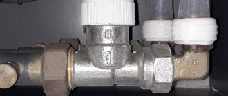
The design of this plumbing fixture is very simple. Essentially, this is a piece of large diameter pipe equipped with threaded fittings for connecting the circuits of the water system. The length of the heating comb depends on the number of connections; the main line is usually connected to the end.
Reference. As a rule, collectors are equipped with outlet pipes of the same diameter, which is 0.5...0.75 from the cross-section of the main chamber. The distance between the fittings varies depending on the coolant flow in the circuits and the purpose of the comb.
What happens in the collector, where water flows from 2...10 parallel branches:
- From several lines, a coolant with various parameters - temperature, flow rate, flow rate per unit of time - enters the collection pipeline.
- In a large flow section of the comb, the speed of water movement decreases and the hydraulic resistance decreases.
- Mixing in the main chamber, different flows acquire the same temperature and speed at the outlet.
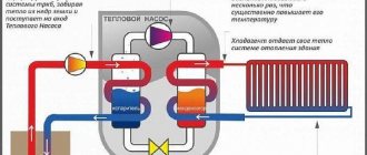
Scheme of operation of a collector pipe for collecting coolant
So, the task of the collector is to collect coolant, equalize its parameters and send it back to the boiler along the main line. You can’t do without a comb when you need to connect several lines with different water flow rates, hydraulic resistance and length into one pipeline. Try to connect such branches on tees - 2-3 circuits will immediately stop working normally.
The heating distribution manifold operates in a similar way, only in the opposite direction. Water from the boiler, flowing slowly through the main chamber, is distributed in the required quantity through secondary lines.
One bare pipe with branches is of little use without accompanying fittings - taps, valves and other elements. The assembled collector unit helps solve several important problems:
- regulate the amount of coolant in each branch, balance them among themselves;
- by mixing, reduce the temperature of the supplied water and maintain it at a given level;
- empty the system, bleed air;
- automatically control the microclimate of each room using room thermostats.
Why do you need a collector in heating?
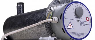
The boiler distribution manifold consists of several devices, each of which performs its own functions. The system has a special heating device that monitors the temperature. If the indicator deviates from normal figures, the valve is activated and the liquid supply is stopped.
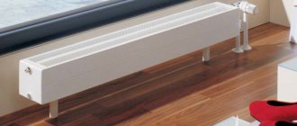
External view of the collector. Photo source: homeprorab.info
Two-way devices are most often used, since they are the most affordable. They are not recommended for installation in rooms whose area is less than 200 m².
Three-way devices have proven themselves well. They are mounted in a system with a large number of circuits. Due to the large bandwidth, there is a high probability of failure. The device is quite sensitive, so even a small angle of rotation can lead to a temperature difference (t).
Types of collector units
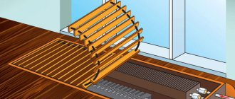
Before considering the types of combs, we will indicate ways of their use in water heating systems of private houses and apartments:
- distribution and regulation of water temperature in underfloor heating circuits, abbreviated as TP;
- distribution of coolant to radiators using a radial (collector) circuit;
- general heat distribution in a large residential building with a complex heat supply system.
On the left in the photo is a coplanar manifold for distributing the coolant among the branches, on the right is a ready-made collector module with a hydraulic switch.
In country cottages with branched heating, the collector group includes a so-called hydraulic switch (otherwise known as a thermo-hydraulic separator). Essentially, this is a vertical manifold with 6 terminals: 2 from the boiler, two to the comb, one on the top to remove air, and water is discharged from the bottom.
Addition. There are cascade water guns with a large number of fittings where the heating circuits are connected directly. Then the manifold type distributor is not used.
Now about the types of distribution combs:
- To limit water temperature, regulate flow and balance heating floor circuits, special collector blocks made of brass, stainless steel or plastic are used. The size of the connecting hole of the main heating main (at the end of the pipe) is ¾ or 1 inch (DN 20–25), the branches are ½ or ¾, respectively (DN 15–20).
- In radiator beam circuits, the same combs of underfloor heating systems are used, but with reduced functionality. We will explain the difference below.
- For general house distribution of coolant, large steel collectors are used, the connection diameter is over 1” (DN 25).
Factory manifold groups are not cheap. To save money, homeowners often use hand-soldered polypropylene combs or buy cheap distributors for water supply systems. Next we will indicate the problems associated with the installation of homemade and plumbing manifolds.
Combs for radiator and floor systems – made of stainless steel, brass and plastic
Comb device for heated floors
The temperature of the coolant supplied to the underfloor heating circuits should not exceed 50 °C, the optimal temperature schedule is 40/30 °C. If the floor surface heats up above 30 degrees, the room will become stuffy and uncomfortable.
Only gas boilers are capable of maintaining a supply of 40–50 °C, and even then with a loss of efficiency. To effectively consume gas or other energy carriers, water must be heated to 60 degrees, and then the temperature at the entrance to the transformer loops must be reduced. This is one of the main tasks of the collector block, consisting of the following elements:
- the collector itself – 2 separate tubes (supply and return) with wall mounting brackets;
- thermostatic pressure valves with connection for Eurocone pipes;
- flow meters (rotameters) with a scale of 0.5…5 l/min;
- end blocks with automatic air valves and drain valves;
- dial thermometer blocks;
- shut-off ball valves;
- bypass line with bypass valve.
Distributor design for underfloor heating systems
Rotameters and pressure valves are screwed into special sockets on the comb, the latter are closed with plastic caps. Air vents with drain valves are screwed into the ends of the collector tubes on one side, and blocks of thermometers and taps on the other. The bypass is installed depending on the design of the comb.
Note. Typically, flow meters are located on the supply line, thermal valves are on the “return” line. But there are also other models of collectors with rotameters on the return line. If you mix up the distributor tubes, you won’t be able to twist the valves instead of the flow meters - the internal shape of the bushings is different.
The thermometers are followed by ball valves, followed by a circulation pump and a mixing unit. Let's consider each element of the collector group separately.
Design and purpose of flow meters
Rotameters are designed to monitor and regulate the maximum fluid flow through loops. The elements are screwed into special pipes on the manifold without winding materials - the seal is an EPDM rubber gasket.
The flow meter body contains a spring-loaded rod with a working plate at one end and a control washer at the other. How does a rotameter work:
- The coolant flows through the side hole in the housing, then moves down, presses on the plate and goes into the pipe.
To adjust the maximum flow on the flow meter using the adjusting washer, you need to remove the protective plastic cap - The more water flows through the flow meter, the greater the pressure on the plate. The spring is compressed, the rod with the control washer is lowered. The flow rate in l/min can be observed on the scale marked on the transparent bulb of the element.
- The amount of flow is regulated by rotating the upper part of the housing. When twisting, the passage hole is partially or completely closed by the piston.
Reference. Some manufacturers' collectors are equipped with unregulated rotameters. To limit flow, separate valves built into the pipe body are used. See the video below to see how such elements look.
Flow meters installed on the return line are designed similarly, only the spring is on the other side of the control washer. The coolant enters from below and pushes the plate upward, the rod and washer rise. How to distinguish between different types of rotameters:
- if, in the absence of flow, the washer is at the top of the flask, then the flow meter is placed on the supply;
- if at zero water flow the washer is at the bottom of the scale, the element is intended for “return”;
- the scale on the flask is graduated in the appropriate direction, in the first case the counting is from top to bottom, in the second – from bottom to top.
During operation, rotameters must be maintained - cleaned when dirty. A transparent bulb serves as an indicator; when it becomes coated from the inside, the element should be unscrewed, disassembled and dirt removed from the working surfaces.
How does a thermostatic valve work?
Structurally, the product is no different from other similar thermal valves - radiator or two-way. When you press the spring-loaded rod, the plate lowers into the seat, blocking the passage of the coolant. It is possible to preset: the maximum flow rate is limited by rotating the valve core using a hex key.
Clarification. There are 2 types of valves - normally open and normally closed. The first ones are described above - when you press the rod, the passage closes. The latter are used less frequently, where the channel is initially closed, and when the rod is lowered, the hole opens.
The purpose of the thermostatic valve is to regulate coolant flow during operation (not balancing!). Management is implemented in 3 ways:
- Manual. The position of the rod is adjusted by a plastic handle, which is screwed onto the valve from above.
- Automatic RTL thermal heads that press the rod when the return flow temperature increases. Do not confuse them with conventional radiator heads that respond to air temperature.
- Electric servos connected to room thermostats or weather-dependent automation.
Manual control requires constant attention from the user - when the ambient temperature changes, you will have to press or release the rod. Thermal heads of the RTL type automate the process, but work well only on short loops - up to 60 m. Servo drives plus thermostats are applicable everywhere.
Other comb accessories
At the beginning of the publication, we listed the tasks that the underfloor heating collector group must solve. With balancing and flow control it is clear - these functions are performed by rotameters and valves. Let's move on to the remaining accessories:
- Terminal unit for emptying and automatically removing air bubbles. The element consists of a housing with a drain valve and a float air vent. The fitting is closed with a plug, which at the same time serves as a thumb for opening the valve.
- Blocks of dial thermometers marked up to 80–90 °C. The purpose is clear - measuring the temperature at the inlet and outlet of the comb.
- Ball shut-off valves. Depending on the method of connecting the collector to the heating, straight, angular, American and internal/external threaded taps are used.
- A bypass jumper with a bypass valve is used in systems with automatic control. If, due to warm weather, all circuits are closed, the coolant will flow through the bypass in a circle, the pump will not work on its own. In normal mode, the valve will not allow water to circulate directly and will force it to move in loops.
From left to right: drain end fitting with manual air valve, block with automatic air vent, ball valves and thermometers
Note. Through the terminal unit, you can not only drain the coolant, but also pump it in in case of repairs. The collector is cut off from the main line by taps, and the TP circuits are emptied or recharged through a side fitting.
The number and variety of additional fittings depends on the comb manufacturer. These accessories are the main ones; in addition to them, various plugs, adapters and valves are also used.
A mixing unit is located in front of the collector block; its composition depends on the method of preparing the coolant for the TP. There are 3 methods of bringing water in heated floors to the desired temperature:
- Mixing into hot water circuits with a two-way thermostatic valve. The element launches portions of the coolant at the command of a thermal head with an external temperature sensor in the form of a copper flask. The latter is attached to the metal wall of the manifold and connected to the head through a capillary tube.
- Mixing cooled and heated coolant using a three-way valve. The principle is as follows: the pump drives water through the bypass along the circuits; when it does not cool down, the valve opens the supply of heated water from the boiler line. The difference from the previous method is a smoother flow and mixing quality.
- Restriction of reverse flow by RTL thermal heads installed on the comb thermal valves. Here a pump module is not needed at all.
You can control a two- or three-way valve in three ways: manually, using a thermal head with a remote flask and an electric actuator. The latter is controlled by a controller that receives signals from room or weather sensors.
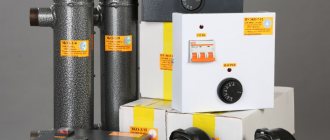
Cost of equipment
Many homeowners are mistaken in believing that a distribution manifold for a boiler room costs exorbitant amounts of money. In plumbing stores you can find many models without any special bells and whistles , which will cost only 200-500 rubles. Such equipment will not have regulation mechanisms, thermal heads and other additional elements, and they are designed for a maximum of 2-3 circuits.
Models with advanced functionality will cost the owner of a home or industrial building who wants to organize a competent heating system approximately 4-5 thousand rubles. A long pipe with several upper and lower outlets will be equipped with thermal heads, flow meters, arrows and other parts. Such designs are often produced by Russian manufacturers or brands from neighboring countries. The most expensive is considered to be imported equipment with automatic adjustment, which will cost 10-16 thousand rubles.
Distributor for radiant heating system
Let us remind you: radial wiring provides for an individual two-pipe connection of each radiator to a common distribution manifold located in a convenient location (usually closer to the center of the building).
An example of radiant heating distribution in a one-story house
To install the collector unit, the following combs are used:
- factory for TP (described above), made of stainless steel, brass or plastic;
- factory for water supply with built-in shut-off valves, made of polypropylene or metal;
- homemade manifolds twisted from brass fittings and polypropylene tees.
The type of comb you choose depends on your budget and radiator system requirements. If each battery is equipped with its own balancing valve and thermal head, then a clean manifold without valves and flow meters is sufficient. Leave the air and water discharge module.
Advice. If you have a limited budget, you can choose an inexpensive water supply manifold with taps, shown in the photo. Many homeowners do this and balance the system with radiator valves.
If you want to automate the heating operation and place all adjustments in a manifold cabinet, buy a comb for underfloor heating. Install all accessories - rotameters, valves with servo drives, air vents, room regulators. A mixer is still not needed; the coolant is supplied to the batteries directly from the boiler room.
The video below shows a combined heating manifold that distributes heat to radiator wiring and floor circuits. Both parts of the comb are installed in parallel. Please note that the master used water distributors to distribute the coolant.
Installation of the collector block
The heating collector is installed in close proximity to the boiler . Radiator pipes from the heater are often laid along the floor, after which the structure is concreted and insulated, which minimizes heat loss. The collector block itself is mounted in a specially prepared panel or wall niche. A special shield can be hinged or built-in, equipped with a door and side stamping, or open. If it is not possible to install a cabinet, then the manifold block is fixed on the wall at a small height from the floor.
If the building is multi-story, then the distributor will be installed on each floor of the house, which will allow heating any room. Such a system will allow you to regulate, connect and disconnect one or more heating radiators, the entire room, a full circuit. This eliminates the need to turn off the coolant supply to other heating sources. Storerooms, hallways, corridors, and wardrobes are used as premises for installing the distribution manifold.
Common house collector group
The main comb performs the same functions as the TP collector - it distributes the coolant among the branches of the heating network of various loads and lengths. The element is made of steel - stainless or black, the profile of the main chamber is round or square.
Reference. Factory-made main manifolds are called coplanar. This buzzword means that all the parts of the comb lie in the same plane - the vertical supply pipes completely intersect the “return” chamber and vice versa. The goal is to reduce the weight and dimensions of the structure.
There are compact models of distributors for 3–5 circuits, made in the form of one pipe. Here's the trick: the return manifold is placed inside the feed chamber. As a result, we get 1 common housing with 2 cameras of equal capacity.
In the vast majority of country houses with an area of up to 300 m², distribution manifolds are not needed. For several heat consumers, a piping scheme using the primary-secondary ring method is used, described in a separate article. When should you think about buying a communal heating comb:
- the number of floors of the cottage is at least two, the total area is over 300 square meters;
- for heating, at least 2 heat sources are used - gas, solid fuel, electric, and so on;
- the number of individual radiator heating branches is 3 or more;
- The boiler room diagram contains an indirect heating boiler, heating circuits for auxiliary buildings, and heating of the pool.
The listed factors must be considered separately and together, and to select a model of specific sizes, the load on each branch must be calculated. Hence the conclusion: it is better not to buy a collector without consulting an expert.
Drawing of a coplanar manifold and photo of the finished product with pumping groups
Design Features
The manifold for a country house boiler room looks like a simple horizontal pipe with upper and lower outlets. Often such products are made of steel or brass alloys. The collector pipe is equipped with shut-off valves, which allow you to cut off the supply of hot media in a timely manner if a problem occurs or regulate the water pressure. Numerous outlets serve as distributors through which the boiler is connected to heating radiators, swimming pools and other objects to which heat is supplied.
This design consists of 8 elements
Other main and additional structural elements of distribution manifolds include:
- Shut-off valves, responsible for shutting off the flow of water on any circuit without stopping the supply of coolant to the remaining radiators and other heating sources.
- Control valves, which can be manual, semi-automatic or fully automatic.
- Auxiliary temperature sensors and regulators installed on taps.
- Valves for draining coolant and releasing air from pipes.
- A supply pipe that transports coolant from the boiler (boiler) to the heating circuits.
- A return pipe designed to pass cooled water through.
- Thermal heads responsible for regulating the degree of heating of the media.
- A hydraulic arrow that acts as a water distributor as it heats up.
The peculiarity of manifolds for heating boilers is the possibility of “extending” the structure. If the number of radiators or other heating sources increases, then you can independently purchase and install thermal heads, flow meters, etc.
In this video you will learn the specifics of the collector:
Installation nuances
The technology for attaching the collector to the wall is quite simple: the TC and radial distribution comb are suspended on mounting brackets, the loops are connected with Eurocone fittings. Pipes going to the top of the collector (usually the “return”) are passed under the bottom.
Advice. No one is forcing you to mount the distributor on brackets. If necessary, the tubes can be spread apart and mounted separately on the wall. The collector box is used in residential areas; when installing the collector in the boiler room, the cabinet is not needed.
Let's briefly list the main points:
- The size of the comb is selected according to the diameter of the pipes used in the heating loops - Ø16 or Ø20 mm. Accordingly, we take a ¾ or 1 inch distributor. The material of the product does not matter; in terms of price/quality ratio, stainless steel wins.
- If the number of comb outlets exceeds 12, assemble a collector assembly of 2 sections. When installing accessories, winding materials are not used, since the parts are equipped with rubber seals.
- A heavier common house collector is suspended on hooks, reinforced brackets, or installed on the floor. Pumps, pipes and other piping elements must not load the distributor with their own weight.
- The hottest coolant receives an indirect heating boiler. The coil and circulation pump of the water heater are connected to the comb directly, usually from the end.
- The radiator heating and TP branches are connected to the manifold through mixing units with three-way valves. A separate pump is installed on each line, selected for pressure and performance.
A heavy coplanar comb can be installed on the floor - weld metal supports
Important point. The mixing unit for heated floors can be installed in the boiler room, near the main comb. Then water at the required temperature will flow to the TP distributor.
Finally about homemade collectors
Above in the text we mentioned budget options for combs - tap, polypropylene and homemade. Such distributors can be used without problems in radiator beam circuits. To balance and regulate the flow, a balance valve and a faucet with a thermal head are installed on each battery. The collector is equipped with “air vents” + drain taps.
If you put the indicated combs on the TP, you will encounter the following nuances:
- the distributor cannot be equipped with rotameters;
- without flow meters it is difficult to balance circuits of different lengths;
- Factory plastic manifolds have shut-off valves, which means there is nothing to regulate the flow;
- combs assembled from polypropylene or brass tees have many joints;
- It's worth noting that homemade distributors don't look too good.
A self-made underfloor heating manifold can still be brought to perfection. We assemble the distributor from tees, and on the return connections we mount thermostatic radiator valves with RTL-type thermal heads, as shown in the photo.
A skilled owner can easily make a coplanar common house collector - weld it from a round or profile pipe. But there’s a catch in the calculations: you need to know the cross-section of the chambers and pipes for a specific heating system. If a specialist calculates these parameters, use the experience of the master from the video: