The Babington burner was originally used to heat buildings and ran on diesel fuel.
The burner's inventor, Robert Babington, patented his device in 1979, and after the patent expired, information about the invention became publicly available.
After this, many craftsmen came up with the idea of using waste oil in the burner instead of diesel fuel.
This is how the modern burner design arose, which is still used today.
Operating principle of the burner
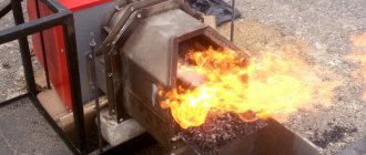
The burner works by atomizing fuel with a stream of high-pressure air. The fuel flows down a spherical surface in which a small hole is drilled. Inside the sphere there is a tube through which air flows under pressure. It bursts through a narrow hole, tears off part of the fuel and sprays it, forming a conical torch.
The rest of the fuel flows by gravity into a special settling tank, which is located under the sphere. It can then return to the main reservoir.
Some consider the principle of operation of a torch to be similar to the principle of operation of a blowtorch, but there is a significant difference between them.
Operating principle of the burner during mining
In a blowtorch, air displaces the fuel, but does not mix with it. And in a Babington burner, a stream of air passes directly through the fuel stream, forming a cone of atomizing aerosol. This ensures better contact of small droplets with oxygen in the air and allows the fuel to burn more efficiently. That is why it became possible to burn oils, while a blowtorch uses gasoline.
When starting the burner, the torch may be unstable, go out, or, conversely, burst out. This is due to the fact that the fuel has not yet had time to warm up properly.
About converting a blowtorch for testing
Some home craftsmen, having studied the operating principle of the Babington burner, are trying to convert an ordinary blowtorch to burn waste oil. The goal is to reduce the cost and simplify manufacturing, because the processes in these two devices are supposedly similar. This opinion is erroneous, since a blowtorch functions differently than the homemade burner described here.
In the lamp, air is pumped into a tank of gasoline with one purpose - to push it out and deliver it to the nozzle. In this case, the fuel goes through the stage of heating and evaporation. The nozzle supplies gasoline vapor to the combustion zone; the liquid can be observed there only at the ignition stage, when the “head” of the blowtorch has not yet warmed up. The used oil will not be able to evaporate and the nozzle will supply it in the form of large droplets, which does not contribute to normal combustion. And the cross-section of the jet will quickly become clogged with various impurities.
The conclusion is simple: it will not be possible to convert a blowtorch to burn heavy liquid fuel.
How to make a burner yourself
The simplicity of the burner design allows it to be easily manufactured in a home workshop or garage. Let's look at how to make a burner of the simplest design.
First of all, you should select materials:
- The body of the future burner is a steel tee with internal thread. Inner diameter - 50 mm.
- The nozzle is made from a squeegee (a piece of threaded pipe). The outer diameter must be 50mm to fit the body. The nozzle length is not less than 100 mm.
- Connection to the fuel line is made through elbow DN 10.
- The fuel line is a copper pipe DN 10, at least a meter long.
- The air duct is a steel tube of the same diameter.
- A metal sphere or hemisphere that can fit freely into a tee.
- Fuel tank and settling tank.
- Heating element for fuel.
The fuel tank should not be located in close proximity to the flare. Otherwise, a fire will occur.
We make a heat generator from a cylinder
First of all, prepare the gas cylinders for welding - remove the spherical parts (don't forget to fill them with water first!) and cut one vessel to size so that together they form a body of the required height (1 m).
We turn out the valve with a pipe wrench and a wrench. If it doesn’t work, then file it and carefully beat it with a hammer.
Prepare the remaining materials, taking into account the following recommendations:
- It is better to make the combustion chamber and flame bowl from stainless steel with a thickness of 1.5-3 mm (for example, grade 12X18H12T);
- if you couldn’t find stainless steel, use black steel grade St3 - St20 from 4 mm thick;
- Also select a stainless steel waste oil supply tube;
- wall thickness of flame tubes – at least 3.5 mm;
- to seal the top cover, select a 40 x 4 mm steel strip (rim) and an asbestos cord;
- prepare 3 mm sheet metal for the manufacture of an inspection hatch;
- For the heat exchanger, use pipes with a wall thickness of at least 4 mm.
Options for manufacturing bowls installed on the bottom of the heating unit
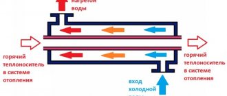
The manufacturing process of a two-pass boiler during testing looks like this:
- Cut the Ø32 mm flame tubes to size and weld the heat exchanger using one cylinder as the outer casing and a Ø150 mm tube as the walls of the combustion chamber.
- Attach the water heating system supply pipes to the heat exchanger.
- In the second cylinder, cut holes for the inspection hatch and chimney pipe. Weld a Ø114 mm fitting and make a neck with a cover from sheet steel.
- Weld both tanks into one body. Make a shell of iron strip on top - it will serve as a seal for the lid. Fill the gap between the edges with asbestos cord.
- Make an afterburner in accordance with the drawing. Make holes in the hemispherical cover (formerly the end of the cylinder) for the viewing window and installation of the afterburner (in the center).
- Equip the lid with handles and a shutter on the window. The afterburner pipe can be tightly welded to it or screwed with bolts sealed with asbestos cord.
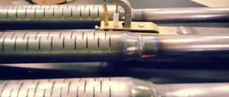
At the bottom end, the perforated pipe is closed with a plug, where 4 holes are made - one in the middle, the remaining three - radially. An oil pipeline tube is inserted into the central hole and scalded. The last step is to make a flame bowl of the boiler where the waste oil will burn.
The lower (end) part of the afterburner with 3 holes Ø4 mm
Upon completion of assembly, weld an elbow with a flange to the afterburner pipe and install the “snail”. To prevent the outer metal wall of the water jacket from wasting heat in vain and heating the boiler room, insulate the body from non-flammable basalt wool. The simplest way is to wrap the insulation with twine and then wrap it in thin sheet painted metal.
The outer casing of the heat generator can be made rectangular
The manufacturing process of an oil-fuel boiler is demonstrated more clearly in the following video:
Step by step guide
Step one is to drill a hole in the sphere. This cannot be done using conventional tools, because the hole diameter should be from 0.1 to 0.3 mm. You need a special drill and a special chuck. If you have a drill with a diameter of 0.1 mm, but the power of such a torch is not enough, you can make two or three holes. Such holes are drilled at high speeds.
When the sphere has a hole, it is attached to the air supply tube. Then the structure is installed inside the tee. A rubber plug is placed at the outlet of the tube from the housing, which is necessary to prevent air under pressure from escaping out. A hole is drilled in the plug through which the tube will pass.
Waste oil burner
A fitting is soldered to the tee on top through which fuel will be supplied. A copper fuel line is connected to the fitting. Of course, the sphere inside the housing must be installed in such a way that fuel from the fuel line falls on it.
The next step is to take steps to warm up the fuel. To do this, a heating element is installed in the tank, which will carry out primary heating and prevent thickening at low air temperatures. The copper tube of the fuel line is bent into a spiral around the nozzle so that the oil heats up even more.
During installation, the nozzle is first screwed on, then the already twisted fuel pipe is put on it, and then connected to the fitting. The lower outlet from the tee is designed to drain the remaining fuel. The settling tank can be placed directly underneath it, but it is better to move it a little to the side, away from the flame.
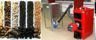
Pellets are wood processing waste. Do-it-yourself pellet burner - operating principle and manufacturing recommendations.
Step-by-step instructions for insulating the floor in a private house are presented here.
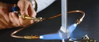
Instructions for making a gas torch for soldering can be found here.
Advantages and disadvantages
The main advantage due to which the homemade burner at the Babington mine has gained wide popularity is its omnivorous nature, as mentioned above. In fact, you can pour any heated oil of a reasonable degree of contamination onto a spherical surface, and a properly made burner will still operate stably. It is not afraid of gasoline or antifreeze impurities, unless their ratio with oil is one to one, then problems will inevitably arise. And then, this is not at all a reason to get rid of such a mixture; for the burner to function normally using waste oil, it will need to be well diluted with the “correct” treatment, and then put into use.
Another advantage is the simplicity of the design, which is why craftsmen quickly mastered this product. Indeed, making the “heart” of the device from a ball or hemisphere placed in a body is quite simple. It is somewhat more difficult to organize the fuel supply and air injection, and even to configure the entire system so that the DIY Babington burner operates stably and safely. But there is wide scope for the implementation of various technical solutions.
Of the serious shortcomings of the unit, only one is striking. This is the constant presence of dirt in the room where the liquid fuel burner operates. Unfortunately, it is impossible to completely eliminate accidental spills or seepage of contaminated machine oil through leaks, even if all connections are sealed and an automatic Babington burner is installed. To one degree or another, the room will be dirty, you will have to come to terms with it.
Manufacturing recommendations
There are several useful recommendations that will help in making a burner:
- The hole should be exactly in the center of the sphere, and its axis should coincide with the axis of the air duct. Otherwise, the torch will hit to the side, and this creates additional danger.
- Instead of drilling a hole, you can use a ready-made jet. To do this, a hole slightly smaller than the outer diameter of the nozzle is drilled with a conventional drill, then it is modified manually, and the nozzle is simply hammered inside.
- If there is more than one hole, the distance between them should not be less than 7 mm.
- To ignite, you need to make a hole in the side of the nozzle.
- In the simplest case, fuel should be supplied to the burner by gravity, but a fuel pump can also be used.
- Even a low-power compressor (for example, from a refrigerator) can cope with air injection. The working pressure inside the sphere does not exceed 4 Bar (4 * 105 Pa).
It is not necessary to use a heating element in the design. When starting the burner, you can use a propane torch, hot water, or even an old coffee maker to preheat the oil.
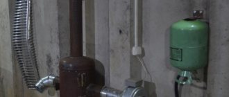
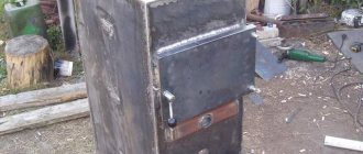
General view of the finished structure
A cinder block block located at the outlet will help maintain the flame.
When the burner is set correctly, there should be no smoke. The only thing coming out is hot, wavy air.
There is an oil pump under the burner. Its task is to suck oil from the tank, where the oil settles, which passes around the propane cylinder twice (at the same time heating up), exits the door handle and, as a result, is sprayed.
Also, to make the design easier to understand, there is no fuel tank; the suspension is immediately poured into the sump. There are various drawings of these burners, but now we are considering the simplest option.
Advantages of this type of burner:
- It is quite easy to make without any help.
- cheap way to generate heat.
- An effective and functional device, it is lightweight, which makes the design mobile.
Starting the system
The serious moment has arrived - testing the burner operating during extraction. We fill the system with oil, turn on the tubular-type heating element and the oil pump, wait until the fuel warms up to the required temperature. Then we turn on the air blower and carefully ignite the burner - a powerful flame will appear, the intensity of which varies by changing the pressure. Now you can connect the burner to the boiler and wait for the heating system to warm up.
You may object - they say, what is the point of this burner if it consumes electrical energy. We assure you that it is impossible to do without electricity. Even store-bought pressurized liquid burners require connection to an electrical network, otherwise it will be very difficult to achieve a powerful flame.
Fuel supply
Amateur craftsmen often supply drip furnaces with single-stage fuel: an oil tank, a ball valve, and a supply tube. Firstly, this is dangerous: for convenience and safety of starting the stove, the valve must be placed closer to it. The supply tube gets quite hot when fuel is supplied from the bottom. If the heating passes through the pipe past the valve, up to which there is a solid column of fuel in the pipe, this could lead to disaster. Secondly, the fuel supply to the furnace is unstable: as the tube warms up, the drops become more frequent, because the oil thins out. If it flows in a trickle, then it is again dangerous.
The drip supply of oil to the furnace during processing should be organized according to a 2-stage scheme: main (storage) oil tank - valve - supply dropper - supply tank (tank) - free flow from it at least 60 mm from the bottom (for additional sedimentation of sludge) - working dropper. The fuel supply is opened when the kindling in the bowl (see below) is lit. While the oil drips into the tank to the level of the drain, you can slowly adjust its flow, and then it drips into the bowl drop by drop.
Scheme of safe power supply of a drip furnace from a supply tank with a safety valve and capillary
This system, however, is not completely safe. If in a hurry, out of ignorance, or simply trying to quickly warm up from the cold, open the valve too much, the consumables will immediately fill, fuel will rush into the stove, and it will throw out a tongue of fire and start spitting burning spray. It would be correct to build a drip oil supply system into the furnace with a safety float valve and a metering capillary (see figure on the right).
Since different metals are wetted by waste in different ways, and its properties vary significantly from batch to batch, the length of the capillary will need to be selected: the oil is fed under a gravitational pressure of 120-150 mm (from a suspended container) at room temperature, and the capillary is selected so that it drips more often, but with drops clearly visible to the eye. A diesel fuel drip furnace can be used from the same feeder, but the capillary will need to be taken with a clearance of 0.6-1 mm and a length 2.5-3 times longer than for mining. There is only one drawback to this scheme for supplying fuel to a drip furnace: the exhaust is dirty fuel, and the capillary will have to be cleaned periodically.
Epilogue
The classic Babington burner is a privilege of the work of craftsmen who make such a device themselves.
It has many positive qualities, but manufacturing companies are in no hurry to put such devices into production.
This may be due to the fact that the fire hazard of such a device and the price are high, due to the complex operating system.
Principle of operation
In most known oil burners, the oil-air mixture is supplied through a nozzle under pressure. In contrast, in the Babington system, oil is supplied by a low-pressure pump and flows freely over a surface shaped like a sphere or close to it. The fuel forms a thin film and evaporates, carried away by a stream of air supplied under pressure into a small (up to 0.3 millimeter) hole in the center of the sphere. Oil vapor and air mix, forming a torch of the fuel mixture. This torch is ignited and heats what needs to be heated - the walls of the furnace or the liquid heat exchanger of the boiler.
Operating principle
Some of the oil does not have time to evaporate and burn and flows below the hole, ending up in the fuel collection pan. The waste then flows from the sump into the fuel tank and is reused.
To increase the fluidity and volatility of the mining, it is heated. The heated waste is sprayed into droplets of a smaller volume, which also improves the quality of the fuel mixture and the overall efficiency of the device.
Starting the furnace
It has already been said implicitly that you need to start the drip furnace slowly and smoothly. Usually, for this they use a torch made from a knitting needle with a piece of foam rubber or a rag: let some drops in and place the torch. When it gets wet, they wait until a puddle drips into the bowl, light a torch, and pour oil into it.
There is a much more convenient and safer way to start a drip stove: a wad of toilet paper soaked in the same oil. They put it in a bowl, set it on fire and slowly regulate the drips, no longer worrying about kindling. Toilet paper is almost pure cellulose; it burns without leaving a residue. Tourists have been warming themselves in tents this way for a long time: the roll is inserted into a wood chip stove, poured with half a glass of alcohol (which also burns without a trace), or the whole thing, darling, and set on fire from above. A lot of heat is generated, and an insignificant amount of fluffy ash can simply be blown out. In the oven it will fly out into the chimney.
Selecting power
The point is that making such calculations yourself according to the formulas is quite difficult. There is information obtained through practice, and it says that different specialists make several holes at once with a width of approximately 0.2 mm.
Sometimes the data is more precise: by making a burner with one hole 0.26 mm wide, you can achieve a burner power of up to 20 kW (depending on what kind of fuel was used).
It is better not to make holes of large diameter (more than 0.4 mm), because this can lead to poor operation of the injector and the processed fuel will burn. In addition, it will be more difficult to ignite the device and excessive consumption of fuel fluid will begin.
Based on this information, it is possible to select the power of the device by the number of holes. To achieve 33 kW, you need to make not one hole 0.20 mm wide, but two.
The distance between them must be maintained at more than 9 mm so that the flames of the fuel mixture do not extinguish each other. In practice, when a Babington burner operates through one hole, 0.26 mm wide, on average oil is consumed continuously up to 2.5 l/hour.
Drilling holes
In order for the air flow to atomize the fuel as efficiently as possible, the hole should be as small in diameter as possible. The priority is 0.010 inches. Although holes up to 0.020 in size are also considered acceptable. To obtain them, special thin drills are used. If you look at them from the side, they will seem intermittent. In any case, the drilling process should be done slowly and carefully. Compressed air will flow through these holes.
As for spraying using air, this option is more preferable than gas. This is due to the low cost of the resource. While you have to pay for gas, you don’t have to pay for air. In addition, you need very little of it, so you can use ordinary compressors, such as those used on aquariums. In principle, the Babington burner, the drawings of which you can find in this article, is almost ready for use. There are a few small parts left.