Pros of the Valtec system
Specification of a Valtec mixing unit for underfloor heating
Before starting installation and selecting a mixing unit for Valtec underfloor heating, it is necessary to analyze the advantages of this type of water circuit.
- Thanks to high-quality materials and durable fasteners, reliable operation is ensured.
- Developed in the form of modules, the components fit together precisely, eliminating the risk of leaks.
- The manufacturer has provided for the production of related materials necessary for thermal and waterproofing equipment.
Calculation instructions
In order to correctly develop a project for laying a heated floor, you will need a preliminary calculation of the main indicators, focusing on their average values.
Do-it-yourself installation of water heated floors
Various factors have to be taken into account, including the role of the water floor as the main type of heating or its use as an additional heat source. Since detailed calculations for independent implementation are a complex process, in practice average parameters are used.
Valtec mixing unit connection diagram
- The rated power has limits of 90 - 150 W/m2. Higher values are selected for rooms with high humidity levels.
- When calculating the laying step, you need to focus on the range of 15–30 cm. The specific heating power is in inverse proportion to this indicator. That is, the larger the step, the less power.
Thermomechanical diagram of a pumping and mixing unit - Despite the fact that with a large diameter of pipes, a larger amount of coolant passes through them, the limiter of this indicator is the thickness of the screed, which is not recommended to be too large, so as not to create excessive load on the floor. Therefore, Valtec pipes are taken into account, made of modern cross-linked polyethylene with an anti-diffusion coating, with a diameter of 16 to 20 mm, and Valtec press fittings are used as connecting parts.
Once the key parameters have been determined, a diagram can be developed in which the most efficient pipe laying is determined on an exact scale. After this, their total length is calculated. At the same time, it is thought through where the pumping and mixing unit and control elements will be located.
The essence of the collector
The main feature of a water heated floor is the coolant; the water gradually moves to the heating circuit and gives off part of its energy.
That is why the heating of the floor occurs with the release of heat to the air that is mixed inside the room, and it, as is known, is directed from the bottom up. A number of devices are responsible for supplying warm water to the circuit and intensity:
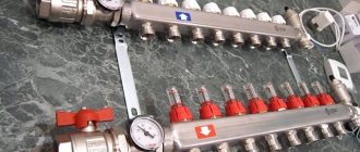
All control of water distribution is carried out using a flow meter. It is this device that plays the main role in the operation of the entire system.
All collectors are designed specifically for hot water, and they are also necessary to collect waste material. In the unit itself, the process of mixing hot water that comes from the source and return takes place.
Thanks to rotameters, there is a chance to ensure that the entire volume of water reaches the floors. Simply put, the equipment will independently control the heat in the water field.
Floor heating cannot do without a rotameter. The design includes a body made of plastic, but there are models made of brass. A float is placed inside any device. There is a flask with a scale.
We recommend: What is film heated flooring?
The float can move up and down and at the same time points to a certain division of the scale. Judging by it, it will be possible to judge the volume of coolant that circulates in the pipeline.
If we talk about theory, the system works without a device, but in this case the adjustment has to be done manually, relying on your own sensations.
The flow meter for the underfloor heating manifold plays an important role; if it is abandoned, the following problems will arise:
Let's say you plan to simultaneously heat the bathroom and another room, for example, a bedroom. A gas-powered boiler will heat water for the bathroom and bedroom absolutely identically, that is, there will be one temperature regime.
It is important to install the equipment correctly; to do this, you need to screw the device itself into the collector socket. Fixation occurs due to the nut. When improving a heated floor, it is advisable to try to control the length of the heat pipeline of all circuits, without paying any attention to the configuration. This will simplify the adjustment of the system and it will still be possible to achieve normal temperature parameters.
But we must take into account that the bathroom is small in size, in order to heat it you need less water from the boiler, but more water is required to supply the bedroom. It is possible to compare the heat of each room, but only in this case will you need to use a flow meter.
If you use this device, the temperature will be set in the bathroom and bedroom for a comfortable stay there.
Having carefully assessed the principle of operation of this device, we can draw the following conclusions:
We recommend: What is the pipe consumption for underfloor heating per m2?
Key characteristics of the mixing unit
In order for the installed water circuit to function effectively, it is necessary to correctly calculate the entire system and correctly install the mixing unit for the Valtec heated floor in accordance with the provisions reflected in the instructions included with the kit.
Connection diagram of the mixing unit to different types of heating
Parameters of the pumping and mixing unit:
- the cross-section of the pipes is ¾ inch, the collectors are 1 inch;
- the design contains 12 pipes;
- the pumping system is 18 cm long;
- the temperature of the heated water in the system is maintained up to 90°C;
- maximum pressure value – 10 bar;
- throughput – 2.75 m3/h. Specification of Valtec pumping and mixing unit
The pipes have an external thread with a Eurocone connection.
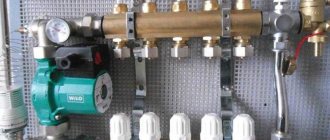
Pumping and mixing unit for heated floors
[ads-mob-1][ads-pc-1]
Video
concerning the functioning of VALTEC products and work with them.
Manifolds for water supply VTc.570Maintenance of membrane tanksInstallation of a circulation pumpInstallation of stainless steel pipesAdjustment of pressure switches VT.CRS5Slide-on coupling made of stainless steel VTi.904New: corner unit for the lower connection of a radiator VT.345.NAWireless room thermostat VT.AC707Service of manifold blocksAdjustment of a safety valveOperation of a three-way valve wound VT. 361Engineering systems of multi-storey residential buildings - part 4Engineering systems of multi-storey residential buildings - part 3Engineering systems of multi-storey residential buildings - part 2Setting up a safety valveEngineering systems of multi-storey residential buildings - part 1 Ball valve with smooth control VT.252Simple and reliable automation for heating systemsWI-FI device for collecting and data transmission water heater safety group control device
Functionality
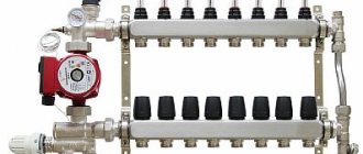
The main purpose of the pumping and mixing unit is to stabilize the temperature of the coolant when entering the water circuit by using water from the return line for mixing. This ensures optimal functioning of the heated floor without overheating.
The Combi unit design includes the following service elements:
- drain valves;
- air vents;
- thermometers. Operating principle of the Combi unit
The following organs are used to adjust the unit:
It is permissible to connect an unlimited number of heated floor branches with a total power of no more than 20 kW to the VALTEC COMBIMIX node
- a balancing valve on the secondary circuit, which ensures mixing in the required proportion of coolants from the supply and return pipelines to ensure the standard temperature;
- balancing shut-off valve on the primary circuit, responsible for supplying the required amount of hot water to the unit. It allows you to completely shut off the flow if necessary;
- a bypass valve that allows you to open an additional bypass to ensure the pump operates in a situation where all control valves are closed.
The connection diagram has been developed taking into account the possibility of connecting to the pumping and mixing unit the required number of floor heating branches with a total water consumption not exceeding 1.7 m3/h. The calculation shows that a similar amount of coolant flow with a temperature difference of 5°C corresponds to a power of 10 kW.
In the case of connecting several branches to the mixing unit, it is advisable to select collector blocks from the Valtec line with the designation VTc.594, as well as VTc.596.
Adjustment methods
Among the ways to regulate the temperature in a water floor system are:
How to adjust the temperature correctly?
The correct setting depends on the optimal and permissible temperature in the premises :
Permissible air humidity is 60%, the optimal is slightly lower - 40–50%.
When adjusting the temperature, adjust the device responsible for controlling coolant flow . It allows you to increase or decrease its flow.
Manual and group
The manual adjustment method for determining the temperature is based only on your own sensations. This measurement method allows for data inaccuracy.
Adjustment is carried out strictly according to the rules:
The temperature of the coolant in the pipes is affected by their length, so it is recommended to use pipes of the same size.
For adjustment, two schemes are used - constants and climate.
Individual and comprehensive
In order to adjust the temperature of heated floors, individual adjustments are made .
It differs from the group one in the presence of separate sensors in each room, which help set a different temperature regime in each room. Another adjustment option is complex. It connects individual and group water floor settings. This method allows you to set a certain temperature regime both throughout the apartment and in each room separately.
Installation algorithm
After the preliminary calculation of all components has been completed, the actual installation of the heated floor begins, which involves going through several stages.
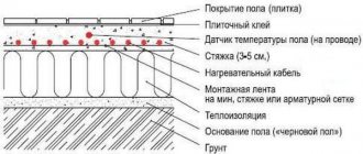
Scheme of water floor heating
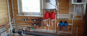
- Installation at a pre-selected location of the manifold cabinet. It contains a module consisting of a collector block and a pumping and mixing unit with ball valves, through which the connection to the high-temperature circuit will be made.
- Preparing the floor plane. If there are significant irregularities, measures are taken to eliminate them. The most effective option is a rough screed.
Connection diagram of the pumping and mixing unit to the heated floor - Fixation around the perimeter of a damper tape, which serves as an element that compensates for the possible expansion of the screed that occurs when it is heated. It is attached to the walls so that after finishing the excess remains, which is cut off before installing the plinth.
- Thermal insulation equipment by laying polystyrene foam boards with mounting bosses on a leveled floor, under which waterproofing is laid if necessary.
- A previously developed diagram serves as a guide for the subsequent layout of pipes.
Settings
To connect pipes to distribution manifolds, a pipe cutter is used to cut the required length, a calibrator, a chamfer and a compression fitting. It is difficult to carry out detailed calculations at home, so be sure to study the instructions, which detail the settings of the pumping and mixing unit in a certain sequence.
- The thermal head is removed.
- For a balancing valve on the secondary circuit, the capacity is calculated using the formula. Two mixing unit options
kνb = kνt {[(t1 – t12) / (t11 – t12)] – 1},
where kνt – coefficient = 0.9 valve capacity;
t1 – supply water temperature of the primary circuit, °C;
t11 – temperature of the secondary circuit at the coolant supply, °C;
t12 – return pipeline water temperature, °C.
The calculated kνb value must be set on the valve.
- Setting the desired operating mode of the bypass valve when setting the maximum pressure difference to 0.6 bar.
- In order for the heated floor to function effectively, the required pump speed is adjusted. To do this, it is necessary to determine the value of the coolant flow rate in the secondary circuit system, as well as the pressure loss that appears in the circuits located after the unit. Equipment for Valtec mixing unit
Flow rate G2 (kg/s) is determined by the formula:
G2 = Q / [4187 • (t11 – t12)],
where Q is the total thermal power of the water circuit connected to the mixing unit, J/s;
4187 [J/(kg•°С)] – heat capacity of water.
To calculate pressure losses, a special hydraulic calculation program is used. To determine the pump speed, which is set using a switch, according to the calculated indicators, a nomogram is used, which is in the instructions attached to the heated floor design.
Connection diagram for heated floor circuits
- Operations are being performed to adjust the balancing valve on the primary circuit.
- The thermostat sets the temperature required for comfortable heating.
- A trial run of the system is being carried out.
If there are no leaks, all that remains is to make a concrete screed, and after it has completely hardened, lay the flooring. [ads-pc-2][ads-mob-2]