A manifold for underfloor heating is a distribution unit that redirects the coolant from the heating boiler through several circuits of the floor heating system. But depending on the configuration of the structure, it may also be assigned other functional tasks. For example, deaerating the system, adjusting the supply of coolant volumes and monitoring its flow using manual or automated flow meters. This actually ensures the maintenance of the required temperature in the heating circuits of the heated floor (HF).
Among heating system installers, due to the characteristic appearance of the collector, another slang designation for it is widespread - “comb”.
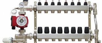
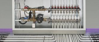
This is what the “comb” looks like
Types of mixing units
The operating diagram of a heated floor collector is quite simple. The coolant from the heating boiler enters the supply distributor. It is recommended to place it at the top (above the return comb), however, depending on local installation features, as well as the type of connected mixing unit, it can also be installed at the bottom. The collector body has two or more branches equipped with appropriate shut-off and control valves. Along each of the branches, the coolant is redirected to certain pipelines of the transformer substations. The output end of the pipe loop is closed on the return comb, which directs the collected total flow to the heating boiler.
Obviously, in the simplest case, a manifold for a water heated floor is a piece of pipe with a certain number of threaded elbows. However, depending on what final configuration it receives, the complexity of its assembly, settings and cost can vary significantly. Let's first consider the most popular basic models of distributors for water TP.
With fittings for connecting circuits
One of the most budget-friendly, but completely ready-to-use, is a comb with inlet/outlet threads and fittings for connecting metal-plastic or cross-linked polyethylene pipes.
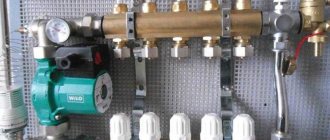
One of these models is shown in the photo.
With integrated taps
In the minimum configuration you can also find a manifold for underfloor heating equipped with two-way ball valves. Such devices do not provide for contour adjustment - they are only designed to turn on or off individual heating branches.
Considering that a heated floor system is purchased and installed to increase the comfort of residents, which is ensured by precise adjustment of the system, the advisability of using such combs is purely selective.
Three-circuit manifold with integrated two-way ball valves
When purchasing these budget options for distributors, it should be taken into account that their use requires fundamental knowledge, as well as extensive experience in installing heating systems.
In addition, purchasing savings are quite conditional, since all additional equipment will have to be purchased separately. Almost simplified manifolds for warm water floors without modification are suitable only for auxiliary systems with one or two loops of short length. They are also suitable for several circuits, but having identical thermal and hydraulic characteristics. After all, the design of such combs does not provide the technical possibility of installing control and regulatory equipment directly on each branch.
With control valves
Example of a comb with control valves
The next level, both in cost and functionality, is a distribution manifold for underfloor heating with control valves. Such devices, when operated in manual mode, can already provide adjustment of the intensity of coolant supply to individual heating circuits. For them, in most cases, it is technically possible to install actuators with servo drives instead of manual valves.
The drives can be connected either directly to electronic temperature sensors installed in the premises, or to a central programmable control device.
Advantages and disadvantages of collector heating
Collector heating in an apartment or private house has pros and cons. Among the advantages of this system it should be noted:
- Maintainability. If a breakdown is detected, you can easily turn off a separate section of the pipeline without completely interrupting the operation of the system.
- Small cross-section pipes can be used. Since each branch leaving the distributor feeds only one radiator, for its installation it is possible to choose pipes of a small cross-section, and they can be easily placed in the screed.
- Easy to use. Due to the fact that each device has autonomous control, the home owner has the opportunity to set the temperature in any specific room. And if necessary, turn off heating devices in the room. Moreover, the temperature in the remaining rooms will remain the same.
- You can install a collector heating system for a private house with your own hands.
Economic costs are one of the disadvantages of this heating.
In order to create several branches that have different characteristics, for example, different coolant pressures, distribution wiring with a hydraulic compensator is used. A hydraulic arrow is a capacious pipe where several independent branches are connected to the outputs.
The coolant heated by the boiler enters the hydraulic arrow. While circulating, water is taken in at different distances from the taps and passed along the contours.
Due to the fact that heated water reaches the radiators with minimal losses, the efficiency of the system increases. This allows you to reduce the boiler power, saving fuel costs.
The heating system also has disadvantages. The main ones:
- Pipe flow. In contrast to the classical connection, the pipe flow during the arrangement of the collector circuit increases by 2-3 times. The difference in costs is due to the number of premises involved.
- Circulation pumps are required, which will entail additional material investments.
If something happens to the pipes, you will have to open the floor
Another disadvantage is the dependence on electricity: even with the boiler running, the radiators will remain cold during a power outage. Therefore, these systems are not recommended for use in areas where power outages are common.
When laying pipes in a screed, you must not forget that any connection is a possible place for a leak, and if problems occur, you will need to open the floor. And this is quite labor-intensive and costly work. Therefore, the circuit wiring connections are made only above the floor level.
Assembly of supply and return manifolds
The economy version of the manifold for a warm water floor also includes paired assemblies of supply and return distributors. They may already have additional mounting holes or installed Mayevsky taps, safety groups, quick-release threaded “Americans” for easy connection to the primary heating circuits or mixing unit.
IMPORTANT! It is strongly recommended to purchase combs not one at a time, but in a ready-made package - a pair with fasteners and technical holes for additional equipment. This will not only significantly speed up the installation process, but will also help avoid many installation mistakes.
Connecting the thermostat
How to connect a heated floor to a thermostat?
Unlike electric floors, a thermostat is not necessary in a heated water field.
But installing it will eliminate the hassle of maintaining a comfortable temperature.
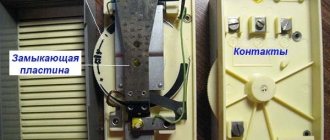
The thermostat refers to a whole system of devices:
- Thermostats are installed in each room and transmit temperature information through the switchboard.
- A servo drive is an actuator that, on command, opens or closes the coolant supply to the desired circuit.
Thermostats can be mechanical or programmable. The first ones are controlled by turning a knob or buttons, but in any case by a person. Software ones are more expensive, control is a little more complicated, but they can reduce the temperature or turn off the system at night when the owner is not at home, on certain days of the week, etc. This saves resources, and the device pays for itself.
The thermostat can be surface-mounted or built-in (that is, installed on the wall using self-tapping screws or recessed into the wall). The installation method does not affect the operation - it all depends on the interior and the taste of the owner.
For water floors, the thermostat sensor usually measures t in the room, and not at the floor surface (the system is more inert than the electric version). But with this approach, drafts can cause errors. The heated floor must be connected according to the connection diagram.
Connection diagram for a heated floor to a thermostat
Connection diagram for a heated floor to a thermostat:
- Choosing a suitable location. For the readings to be accurate, there should be no radiators on the wall where the sensor will be located. The device must not be exposed to sunlight. Height from the floor – 1-1.4 m.
- If there is only one circuit, a switch is not needed. The thermostat is directly connected to the servomotor.
- Or the thermostat is placed in the circulation pump control circuit. In this case, all circuits will be interconnected, and the temperature will be regulated equally throughout the house.
- You can check the operation using an external thermometer. Set the desired thermostat mode and measure t at the location where the temperature sensor is installed for several hours. There should be no strong temperature fluctuations.
After the system is assembled, its tightness is checked. A successful test allows you to move on to the next stage - pouring the screed and finishing the floor.
It is necessary to carry out the work of pouring the screed without turning off the water, so that the pipes are under pressure and do not deform.
Electric boilers are rarely used due to high energy consumption. However, they are safe and their cost is low, unlike, for example, gas. How to choose an electric heating boiler? Read carefully what options you need to pay attention to when purchasing.
Read about energy-saving heaters for your home in this topic.
From simple to complex
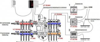
A fully equipped manifold for underfloor heating can be assembled according to several working schemes. However, they all have a similar operating principle. One of the typical assemblies consists of the following elements:
Tap on the distribution comb.- Flow meters (rotameters).
- (a/b) Taps for draining coolant from the supply and return lines, respectively.
- Manual valves for adjusting coolant flow.
- Pressure gauge.
- Return valve.
- Three-way valve.
- Circulation pump.
Let's consider the most functionally significant elements of the device, their main types and purpose.
Pipe selection
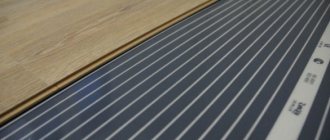
Although pipelines made of various materials can be used to supply water and install circuits, in everyday life they mainly use polymers, which are supplied in coils of various lengths and are easily bent when laying loops.
The main materials of heating pipelines are: metal-plastic made of cross-linked polyethylene PEX with an aluminum layer between the inner and outer shells, cross-linked PEX and heat-resistant PE-RT polyethylene.
It should be noted that metal plastic is not very practical as a material for heated floors - due to its high rigidity, it is difficult to bend with a small radius, and mechanical impact on the surface during installation or before laying the screed leads to bends and breaks. You can repair a metal-plastic pipeline by inserting a section connected using compression or crimp fittings - this leads to a decrease in the passage channel and an increase in hydraulic resistance.
Pipes made of cross-linked and heat-resistant polyethylene have the same service life of about 50 years; it is believed that the PE-RT pipeline is easier to install in rooms with low temperatures, and if damaged, it can be easily repaired by soldering, although the technology is not very well known. Also, the cost of PE-RT is lower than cross-linked polyethylene PEX, although there are enough products of both categories at a relatively low price on the construction market.
Rice. 19 Basic pipe laying schemes for heated floors
Adjusting the coolant supply
If the warm floor in the apartment has several circuits that differ in length or temperature conditions, installing a heating distribution manifold with flow meters (rotameters) will help out. The fact is that the coolant follows the path of least hydraulic resistance, that is, first of all, it will be directed into short-length pipelines.
In order for large loops to heat up with the same intensity, it is necessary to adjust the fluid supply, reducing it for short pipelines and increasing it for longer ones. Therefore, the water heated floor comb is equipped with a balancing rotameter for each loop.
The flow meter scale determines the intensity of coolant flow in a particular circuit. And in accordance with these indicators, the throughput of the flow valve is adjusted.
The purchase and use of adjustable rotameters is justified only in the case of manual adjustment of the amount of coolant for circulation through the branches. If each circuit is regulated by its own servo drive under the control of an electronic thermostat, then the use of such fittings is not required.
At the same time, in the collector block operating in automatic mode, for additional visualization, rotameters without a control function can be mounted. However, such devices are no longer installed on top of the comb body, but are embedded between its outlet for connecting the loop and the outlet of the heated floor pipeline.
Why do you need a collector?
Essentially, a collector is a pipe with holes for the inlet and outlet of the coolant; it is also called a distribution and mixing unit. The function of the device is to maintain the required temperature level in the system and control the water flow.
The device is designed to mix water coming from the boiler, where it is heated, with cooled liquid coming from the return line to the required level for heated floors. After all, in a boiler the coolant usually warms up to +90 degrees, and for a heated floor this is a high temperature.
It requires +40 - 45 degrees, so you can’t do without a collector. If water flows directly from the heat source into the circuits, this will lead to overheating of the system and its failure.
In addition, the circuits have different lengths, and their need for thermal energy is different. Therefore, a special unit is needed between the boiler and the pipeline, which will distribute the flow of hot water through the loops.
Adjusting the coolant temperature
Adjusting the temperature of a heated floor should contain two main stages.
The first concerns the general preparation of the coolant when it is taken from the high-temperature heating system of the primary circuit. It is carried out through the interaction of the elements of the pumping and mixing unit (PSU, Fig. 6, item 7 and or the mixing and control unit.
Typically, the main elements of the first stage of coolant preparation are a circulation heat pump and an automatic three-way valve or an automatic three-way valve without a pump. The task of the mixing units is to bring the temperature of the primary coolant (70-90°C) to 40-50°C acceptable for water heating of floors.
The design and operation of the NSU are described in detail in our separate article. However, it should be clarified here that the manifold may include a mixing unit or be assembled without it. If floor heating consists of an extensive network of thermal circuits and contains several manifold distributors, then the NSU (due to its high cost) is optimally placed in a unit common to the entire system.
If there is only one collector, then it can be immediately combined with a mixer in a single installation cabinet.
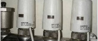
The second stage of adjusting the temperature of the heated floor directly concerns the equipment of the comb, where the thermal parameters of the circulating fluid are leveled in accordance with the requests for each branch. Individual temperature adjustment for each circuit is carried out using mechanical thermostatic valves or automatic valves with servo drives (photo).
Servo drives, receiving commands from an external thermostat, are actuators for controlling the operation of the water-heated floor collector. Although such automation is quite expensive, it provides the opportunity to organize more comfortable heating conditions.
The working parts of thermostatic shut-off and control valves, both mechanical and controlled by servo drives, are mounted on a return comb instead of manual valves.
As a result, the assembled manifold for underfloor heating with flow meters, thermostatic mechanical heads and an automatic three-way valve may look like the one shown in the figure.
Conclusions and recommendations
Judging by the reviews on the forums, homeowners are familiar with combs equipped with a mixing unit and a pump. It is noteworthy that not all craftsmen know about the existence of RTL-type thermal heads. And they can significantly reduce the price of a heated floor comb installed in a small or medium-sized country house (up to 250 m²). Here are the recommendations:
- If possible, use a factory or homemade comb with RTL thermal heads, then you won’t have to buy a circulation pump and valves. The main condition is that the length of the contours is no more than 60 m.
- If the number of loops reaches 10 or more, and the supply line from the boiler is quite long, select a more powerful main pump. You can install the Grundfos Alfa-2 15-60 unit with the Autoadapt function to save electricity.
- For circuit lengths up to 100 m, house area over 250 m² and a complex heating system, use a comb with a two- or three-way valve (quality control).
- If possible, equip the comb and underfloor heating system with automation. To do this, it is recommended to consult with a specialist in this field.
Note. Designers and manufacturers of components for heated floors categorically do not recommend making the pipe length in one loop more than 100 m (Ø16 mm).
It is advisable to avoid a situation where the distribution comb is on the 1st floor, and heated floors are installed on the 2nd and 3rd floors. It is better to place the node closer to the contours and run 2 lines to it, instead of laying 10 or 20 pipes from the comb along the walls and through the ceilings. You will get answers to many questions by watching the video:
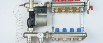
Security group
The safety group for the underfloor heating manifold may have a slightly reduced version. This is due to the fact that the heating system must be equipped with an appropriate device located near the boiler.
The underfloor heating manifold can be equipped with an automatic air vent with a tear-off valve, as well as a drain valve (preferably with a hose attachment) to remove coolant from the system. All this is attached to the end of the comb on a special adapter.
It is recommended to install such a group on both the feed and return combs. Photo Figure 10 shows just such an assembly option. It also includes American-style shut-off valves for supplying/removing coolant from the main supply/return and thermometers for easy setup of the water heated floor system.
Pipeline laying options
The main pipe laying schemes during installation are zigzag and spiral volute, the latter provides more uniform heating and is considered the best in efficiency. When laying pipes, a certain distance between sections must be maintained; it depends on the layout and thickness of the screed; its typical value for the usual thickness of the cement-sand layer is in the range of 150 - 200 mm.
The distribution manifold is the main unit in an individual heating system containing two or more underfloor heating circuits; it performs the functions of distributing and mixing the coolant to reduce its temperature. During installation, a pipeline made of cross-linked or heat-resistant polyethylene is placed under a screed in the form of a zigzag or snail and connected to the combs using Eurocones, which ensure a quick and tight connection.
How to choose a manifold for heated floors
The main parameter for choosing a manifold for a heated floor is the number of circuits to be connected.
Expert opinion
Sergey Permyakov
Heating systems engineer
We recommend purchasing a comb with a reserve of one output, in case it becomes necessary to split an overly long circuit into two branches or connect additional monitoring equipment (thermometer, pressure gauge).
The second selection criterion is the material used to make the comb body. Reliable products are manifolds made of brass or stainless steel, as well as bronze, manufactured in accordance with domestic GOSTs or European quality standards. “Chinese” ones made from dubious alloys can be purchased only after the seller demonstrates a certificate of conformity, and the comb itself has been thoroughly examined for cavities, cracks or traces of corrosion.
Although in fact most modern products, if not all those on the market, are produced by Chinese enterprises, when choosing them, preference should be given to well-known brand names. After all, reputable European companies carefully monitor the quality of work of their production facilities, even those located in the Middle Kingdom.
First of all, pay attention to products under the brands: Rehau, Kermi, Valliant, Valtec, FIV, Rossini. It is best to purchase a manifold for underfloor heating from such companies as a complete set. Purchasing individual elements will cost more, and components from other manufacturers may be incompatible with installation parameters.
Features of installation of the collector system
Installation of heating systems is carried out before finishing work on laying floor and wall coverings; the pipeline running along the floor is tied to a strong metal mesh and filled with a screed located on the insulation layer.
Apartment house
The implementation of collector heating in a residential apartment building is practically not used in everyday life, this is primarily due to the presence of radiator heating in buildings, in which all rooms in the apartment are heated by radiators. Laying circuits for heating rooms through floors is associated with significant financial costs and is ineffective; moreover, a comb is not required for laying a small number and short length of loops. A significant factor that makes the installation of collector heating in an apartment building useless is the imbalance and violation of the temperature regime of the entire house system, as a result of which penalties and dismantling of the installed heated floor are possible.
Cottage
Collector combs are the main elements in organizing heating of country houses and cottages; they are usually placed in the wall of rooms located in the center of the house on each floor, connected to a riser built into them.
To do this, during the construction stage, a recess is placed in the wall in which the comb is placed; to improve the aesthetic appearance, a manifold cabinet with closing doors is placed in the place of insertion.
One circuit is used for each room; if there are several radiators in the room, they are connected in series using a single-pipe passing or pass-through circuit (Leningrad). Several small circuits are installed if the area of the premises is large and the maximum length of the pipeline does not ensure its coverage at a given pitch.
Rice. 14 Combined heating system