VALTEC SrL was founded in Italy in 2002 and specializes in the production of equipment for thermal systems operating in difficult conditions. Currently, it is highly respected among consumers in various countries, including Russia. In terms of price, it is considered affordable for most users and fully meets European quality standards.
VALTEC
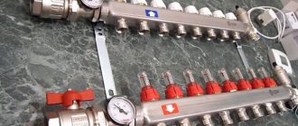
Valtec underfloor heating manifold with rotameters
The parts are made of CW617N brass and AISI 301 stainless steel. The manifolds have adjustment and shut-off valves, drain valves, and automatic air vents. All seals are made using EPDM rings, the standard for connecting Euroconus pipe loops. Some models have additional equipment that allows you to fully automate the operation of the devices. The number of outlets ranges from 2 to 12, diameters 1″ and 1 1/4″. The warranty on all company equipment is 7 years, maximum operating temperature is +120°C, optimal pressure is 10 Bar.
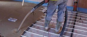
Starting a water heated floor
Putting a water heated floor into operation consists of several stages. The first step is to start water circulation through the circuits and expel the air. To do this you need:
- If the system is filled with water, then check that all taps are open so that circulation is possible not only inside the heated floor circuit, but also outside the system, because the mixing valve will try to take hot water from the system.
- Set the handle or thermal head of the mixing valve to the minimum temperature position.
- Start the circulation pump of the floor heating circuit. In this case, it is better that the boiler is turned off, because... the boiler pump will interfere with operation.
- If manual air vents are installed on the end elements of the manifold, then bleed off the accumulated air from time to time.
- Check with flow meters that circulation is flowing through all circuits. Often, from the underfloor heating collector on the first floor, a branch goes to the second floor to the bathroom. If there is no automatic air vent insert at the top, then it will be difficult to remove the air from it. To do this, you need to shut off the remaining circuits and set the pump to maximum speed so that all the pressure goes up. If this does not work, you need to stop the pump and run the circuit with water pressure. To do this, close the supply valve to the collector, all circuits of the collector are closed, except for the top one, and sharply open the drain valve on the return collector. The water coming out under pressure will displace air; it may be necessary to open the system's supply from the water supply.
- Bleed the entire heating system. Some of the air from the heated floor circuits will enter it.
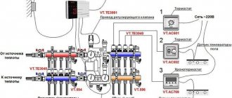
Figures 1 and 2 respectively show manifolds without flow meters and with flow meters. The numbers on them indicate the corresponding elements:
Optimal design of the collector group
The optimal design is considered to be a manifold group in which the supply manifold is equipped with a rotameter, and a thermostat is installed on the return manifold. Such a system will allow the required amount of coolant to be directed to each circuit, and the return manifold of such a system will open and close the circuits as the water cools.
It is also worth noting that the system can be improved with an automatic air vent, which is installed on the supply manifold; in turn, it should be connected to a bypass with a bypass valve.
It will work like this:
- Air vents will remove air from the system that interferes with its normal operation;
- If it gets warmer outside, the thermostats will close the circuits, and the bypass valve will reduce the increased pressure inside the system.
Speaking about how a heated floor flow meter works, it is worth making an amendment: there are three types of rotameters:
- The measuring rotameter is installed together with a valve, which is adjusted independently, depending on the measured readings;
- The regulating rotameter controls the amount of incoming coolant;
- The third type combines the previous two, but it also has an increased price.
Hydraulic leveling of water heated floors
We have a water heating system, which includes water heated floors, based on a pumping and mixing unit and a conventional manifold with or without flow meters. It is a reliable, safe, comfortable and well-managed underfloor heating system. In order for it to become such in reality, and not just on advertising brochures, it needs to be configured.
For a water floor in a private house, it is better to use collectors with flow meters; in this case, it will be much easier to manage the system. If you are reading this article, but you have a similar heated floor in an apartment or house with central heating, then pay attention to the maximum operating pressure of the collector you have chosen; usually for collectors with flow meters it is 6 bar. This may not be enough for a central system.
If you have servos on the collector that are controlled automatically, then they will regulate the coolant flow as necessary. However, it will be necessary to pre-set the flow in the circuits. If you have a collector without drives (in the vast majority of cases), then this setting is simply necessary.
The coolant flow through the circuit can be calculated using the formula:
Further, in order to obtain the required calculated coolant flow through the circuit, it is necessary to multiply the specific flow rate Gsp ((l/h)/m2) by the floor area S (m2) served by this circuit.
So, the simplest way to hydraulically level a heated floor is:
- calculate the water flow through each circuit by multiplying the floor area through which this circuit passes by 8.6; thus, we obtain the flow rate in l/h;
- turn on the underfloor heating pump, set it to first speed (for an average private house);
- set the thermal head or mixing valve handle to a position of approximately 30 o C;
- make sure that water circulates freely through the branches and air is expelled;
- adjust the kennel in such a way as to achieve the flow rates obtained in step 1 on each flow meter;
These actions will provide the so-called “pre-tuning”. If everything is calculated correctly, then it will be quite enough. But in fact, during operation, underfloor heating may need to be adjusted based on the feeling of comfort. When setting up, it is necessary to understand that the circuits are hydraulically interdependent; “screwing” one can increase the flow through the other. You also need to be prepared for the fact that the boiler pump and the heated floor pump will influence each other. This is not scary, but when the boiler pump turns on, it is impossible to adjust the heated floor; you need to wait until it stops.
Assembly of the mixing unit
When faced with such a seemingly difficult task, you first need to understand in detail the intricacies of this process. Below is an example of assembling a mixing unit with your own hands; the assembly will be made from metal components.
We will assemble it according to a scheme in which there is a thermostatic three-way mixing valve and a series connection of a circulation pump. To seal the seams, use flax tow and sealant paste; good reviews of Unipack paste.
You will need the following materials:
- Union nuts, American.
- Manual air vent.
- Nipples.
- Circulation pump.
- Thermometer.
- Check valve.
- Ball valve.
- Tees.
We are assembling on the basis of a three-way mixer of the ESBI thermostatic valve; the box indicates in which direction the water is mixed. The operating outlet temperature is 20-43 degrees Celsius, which meets the requirements for a heated floor system. This mixer already contains a thermostatic head, a temperature sensor and a temperature controller that allows you to set the temperature you need. On it itself, arrows indicate in which direction cold and hot water flows.
Wilo has proven itself well in this niche. Having picked it up, inspect it, determine in which direction it pumps liquid. Determine the direction of the drive axis; during installation, it should be located horizontally; this is one of the mandatory operating conditions for pumps that have a wet rotor installed in their design. Another prerequisite is that the switching box cannot be located under the pump.
If, nevertheless, it becomes this way for you, then rotate the upper element of the housing to which the box is connected 180 degrees. This can be done by using a hex wrench to unscrew the four screws that connect the two halves of the pump.
Then carefully rotate the upper element relative to the lower pump element. Put everything back together and tighten the screws. Photo of an example of a mixing unit for heated floors
Photo of an example of a mixing unit for heated floors
The next thing we have to do is to install thermometers on the pipe where the supply takes place before the mixing process, then after the pump. Install the latest one at the outlet of the return manifold. Choose temperature sensors equipped with a probe that screws into central sockets. It would be advisable to verify each device.
Since in one chain they are subject to the same pressure, accordingly, their values should be the same. If possible, check with a reference device. If one of the devices has different readings, you can adjust this yourself. If you remove the cover, you will see a screw that you can use to adjust the readings.
So, the installation steps:
- Assemble the section from the primary supply to the mixing valve, connect the shut-off and ball valves and the tee under the temperature controller. Each of the four taps must be equipped with a union nut. This is done for ease of future maintenance.
- Connect the next outlet of the concentrate to the inlet pipe of the mixer with a three-way valve. Install a thermometer in the central socket of the tee.
- Install a bypass jumper, screw a coupling with an American connection to the second input. This is for ease of installation during maintenance.
- Then connect the tee to the jumper; one side should be facing the return of the system, and the other to the collector.
- The common return element includes one shut-off ball valve. There is no need to install a check valve, since most likely it will not be useful.
- Then assemble a parallel section. Install the temperature sensor by first screwing in the tee.
- Then it was time to assemble the element between the pump and the supply manifold. It includes a coupling with an American connection, a triple connecting element for the temperature regulator, an extension cord, and a shut-off valve.
- Install a ball valve near the manifold.
- Screw the coupling onto the outlet of the mixing valve.
- Well, the almost final stage is the installation of a circulation pump. Insert the rubber O-ring and tighten the nut on the inlet pipe of the pump.
- Screw and crimp the union nut on the other side in the same way. So the mixing unit for the heated floor has been assembled.
This was the final step, then place this element where it will be installed.
Temperature equalization of water heated floors
With the help of water heated floors, you can regulate the temperature of the floor surface and the air temperature in the room. In those rooms that, in addition to heated floors, also have radiators, it is better to provide the radiators with the opportunity to maintain the air temperature, and the heated floor will provide a comfortable surface temperature.
It must be remembered that the standards limit the surface temperature of heating structures, incl. for heated floors in rooms with permanent occupancy (bedroom, living room, etc.), the surface temperature should not exceed 26-29 o C. In rooms with temporary occupancy (bathroom, corridor) - no more than 35 o C. In fact, often Residents of houses violate these norms due to their ignorance or inability to use the system. In addition, flooring manufacturers also have temperature restrictions. So, if you don’t have tiles, then you should raise this issue and look at the technical documentation for the flooring.
The surface temperature of a heated floor is complexly dependent on the temperature of the coolant in the supply and return manifolds, as well as on the flow rate and specific thermal power, and, in particular, on the design of the floor and floor covering. Let us highlight the main thing: with the following calculated or actual indicators, you need to be wary of an increase in the temperature of the floor surface above normal:
- the water temperature in the supply manifold is above 45 o C;
- the calculated specific thermal power of the heated floor is more than 120 W/m2
You can select your individual underfloor heating parameters in the online underfloor heating calculation program. Enter your initial data and try experimenting with the indicators.
So, the temperature control of a water heated floor can be done manually using a thermal head or a rotary knob on the mixing valve. At the same time, remember to limit the surface temperature. It is necessary to pay attention to the fact that regulating the temperature of the coolant in the heating system as a whole using the boiler has practically no effect on the heating circuit of the floor. It is also possible to automatically regulate both the floor surface and the room temperature. For this purpose, automation is used, based on servos, air temperature sensors, floor temperature sensors and control controllers.
Practical advice for setting up underfloor heating systems
Installing an underfloor heating system is undoubtedly a responsible operation, however, how comfortable it will be to use the finished heating system most often depends on proper setup. Setting up an underfloor heating system is not as complicated as it might seem at first glance.
By and large, setting up a heating system consists of three stages. This includes balancing underfloor heating loops, setting up the pumping and mixing unit and setting up the controller, if available.
This article will cover the methods used to balance underfloor heating loops. First of all, it is worth noting the main misconceptions that occur during such balancing.
So, the heating system is filled and tested, the boiler is started, the hex key is in your hands, giving off a pleasant heaviness that turns into an itch of impatience. Where to start?
First of all, it is worth deciding on the goals and objectives of balancing.
The task of balancing is not to set the required flow rate for each loop, but to set the ratio of flow rates across loops or the flow balance. The final costs are determined during the setup of the pumping and mixing unit. At the same time, by changing the total flow rate through the collector, the ratio of flow rates through the loops is maintained.
Balancing also differs depending on whether the collector block has flow meters. VTc.596 collector blocks ( Fig. 1
), VTc.589 (
Fig. 2
), VTc.586 (
Fig. 3
) are equipped with flow meters that significantly speed up balancing and allow it to be carried out without turning on the boiler, since they show in real time the water flow in each direction.
The distribution of costs must be done in such a way that the ratio of flow rates across the loops and the ratio of the required thermal powers coincide. To do this, it is advisable to know the required thermal loads on the loops. But even if the required loads are not known, then costs can be set in proportion to the lengths of the loops. As a rule, this approach does not give a large error, since loops with large lengths also have greater powers.
Balancing begins by selecting the longest loop (or the loop with the highest power, if known). The control valve on this loop opens to the maximum position, and the flow rates of all other loops will be set relative to it.
For example, let's take a manifold with four loops. Let us assume that the loop lengths are as follows: 100, 75, 75 and 50 m.
In this case, the adjustment begins with the first loop, which has a length of 100 m. It opens to the maximum. Let's assume that with the valve fully open, the flow rate on this loop is set at 4 l/min.
The water flow on the second and third loops should be: (75/100) · 4 = 3 l/min.
The water flow on the fourth loop should be: (50/100) 4 = 2 l/min ( Fig. 4
).
It may happen that when setting up the third loop, the flow rate, even with the valve fully open, is set at 2.5 l/min and does not reach the required level of 3 l/min. This means that the loop has greater hydraulic resistance than the second loop of the same length (more branches, rolls, supply sections). In this case, balancing can only be done with the boiler on and at least with minimal heat removal in the room. The first loop is at (100/75) 2.5 = 3.3 l/min, the second loop is at 2.5 l/min and the fourth loop is at (50/75) 2.5 = 1.6 l /min ( Fig. 5
).
After all costs have been set, the balancing of the loops can be considered completed and you can begin setting up the pumping and mixing unit.
If you configure collector blocks without flow meters, such as VTc.588 ( Fig. 6
) or VTc.594 (
Fig. 7
), then the flow rates in the loops can be judged only by indirect evidence.
In this case, balancing can only be done with the boiler on and at least with minimal heat removal in the room. It is advisable that the outside temperature be below +5 ºС. There should be no open windows or any significant heat emissions (working fireplace, etc.) in the premises. The setup, as in the previous case, begins by determining the longest loop.
The system must then be left to warm up for several hours until the temperature in the loops has stabilized, after which the correctness of the settings must be assessed.
Determining the correct setting based on the return water temperature
Coolant flow, power and temperature difference between the supply and return pipelines are interconnected. If you reduce the coolant flow in the loop, the temperature difference will inevitably increase. It is by this dependence that the correct setting can be determined.
If all loops have the same temperature difference between the supply and return pipelines, this will mean that in all loops the water flow corresponds to the current power. And since the temperature in the supply manifold is the same for all loops, it is possible to equalize the temperatures only in front of the return manifold.
It is most convenient to assess the temperature using a special thermometer, such as VT.4615 ( Fig. 8
).
Such a thermometer is inserted between the pipe and the return manifold through a Eurocone connection ( Fig. 9
).
A reference temperature is determined on the longest loop, then all other valves are adjusted depending on deviations from this temperature. If the temperature on the loop is lower than the reference temperature, this means that the flow rate in this loop is also low, and the valve should be opened slightly. If the flow rate, on the contrary, is higher, then the valve should be closed. Then, after half an hour, this operation should be repeated until the water temperatures in front of the return manifold are equal for all loops.
Determining the correct setting based on the average floor temperature
The previous method is quite simple, but does not take into account the finishing floor covering. If rooms have different floor coverings, then in order for the floor surface temperature in these rooms to feel the same, it is necessary that the costs for the loops take this factor into account.
You can take into account the finishing coating by measuring the temperature of the floor surface in different rooms and equalizing the water flow in different directions so that the average temperature of the floor surface in different rooms is the same. You can measure the floor temperature in different ways: with contact thermometers and pyrometers ( Fig. 10
).
Setting the valves is the same as in the previous case. The valve servicing the loop, the floor above which has a temperature higher than in other rooms, is closed and vice versa - when the floor temperature is low, the valve opens.
It is worth noting that you need to measure the floor temperature at at least six points: above the pipes, between them, at the beginning of the loop, in the middle and at the end of the loop, and take the average value.
When the floor surface temperature in all rooms reaches similar values, the adjustment can be considered complete.
In order to protect the valve settings from unauthorized intervention, the VTc.594, VTc.588 manifolds have a mechanism for fixing the adjusted position. To fix the setting, you need to tighten the fixing screw until it stops ( Fig. 11, 12
). The screw is located inside the hexagon. This screw limits the valve to open at its current level and prevents it from opening further. However, it allows the valve to be completely closed. Thus, after adjustment, you can tighten all the fixing screws until they stop, and in further operation you can close individual loops with the same valve. Next, in order to adjust this loop again, you should simply open the valve all the way.
As you can see, setting up hinges is a fairly simple operation, especially if you use convenient equipment for this. Setting up a pumping and mixing unit (PMU) also does not raise questions for most installers. Some features of setting up the NCS will be discussed in a separate article.
Source
Warm floor and the space occupied by the manifold with flow meters
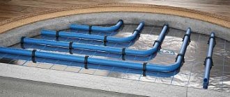
The peculiarity of a heated floor as a heating system is that the heated coolant, moving along the heating circuit, transfers part of the thermal energy to the floor surface. Thus, by heating the floor, heat is transferred to the air mass circulating inside the room in the direction from bottom to top. A number of devices control the supply of warm water to the heating circuits, the intensity and flow rate, including:
The distribution of the coolant is controlled by a flow meter for heated floors. This device plays one of the key roles in the operation of the entire pumping and mixing group. Heated floor collectors are designed to supply hot water and collect waste coolant for its further use in the heating system pipeline. In the pumping and mixing unit, hot water coming from the heating source is mixed with the coolant returned to the circuit - return. The functionality and efficiency of heated floors is based on this operating principle.
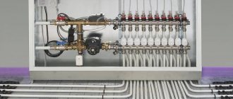
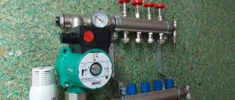
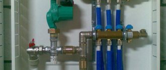
Mixing unit with rotameters for a warm water floor system
Together with the operation of safety valves, rotameters are designed to regulate the temperature of the coolant in individual circuits of the water floor. Thanks to these devices, the required volume of prepared water entering the warm water floor system is ensured. In other words, this equipment monitors the amount of coolant in the water heating pipe, and therefore the functionality of the entire heating system.
Select the bypass adjustment value 0-5 depending on the situation.
Using the example of these two mixers, we can now show the difference between the different bypass adjustments of the TIM JH-1036 mixing unit.
Bypass setting value is 0.
The first mixer operates in conditions where the bottleneck of the system is the heat supply from the system.
It is connected like a radiator in a one-pipe system.
Just in case, I made a thickening at the connection section from 25 to 32 diameters and installed a tap, since I doubted that a sufficient amount of water would flow in and provide sufficient power.
This local heating subsystem is built, of course, on one mixing unit without a collector group.
There should be no problems with circulation along one circuit.
Therefore, we set the value of the bypass adjustment bolt to 0.
We make the circulation through the heated floor circuit minimal, and the circulation through the mixing chamber maximum.
It was shown above that here the mixer pump will help the circulation through the heating system a little more.
Bypass setting value 5.
In this case, on the contrary, the heated floor mixer is connected directly to the boiler in parallel to a single-pipe system with batteries.
There are no problems with supplying the required thermal power to the mixer.
Flowmeter functionality
A rotameter or, to give a full definition to this unit, a float rotameter, at first glance, is a common mechanical device. The design of the product is based on a plastic case (there are models made of brass), inside of which there is a polypropylene float. The body is equipped with a transparent bulb on which a marking scale is applied. The movement of the float up and down inside the device indicates a certain value on the scale, by which one can judge the volume of coolant circulating in the pipeline system - whether it is enough for the full operation of the heating circuits.
Traditional flow meter for underfloor heating manifold in various versions: on the left - in a plastic case, on the right - in brass.
From a theoretical point of view, the heating system can operate without this device. In this case, you will have to manually adjust the volume of water entering the circuit, based on your personal feelings when the air temperature in the room changes.
Note: by the sound of the operating pump and the intensity of heating of the heated floor, one can judge the degree of completeness of the supply of hot coolant to all heating circuits.
Refusing to use a flow meter when installing heated floors is fraught with the following problems:
- individual circuits of the water floor will be supplied with coolant without taking into account the characteristics of the room, as a result of which the temperature values of the floor surface of heated rooms will differ;
- the energy consumption used to operate heating devices (electricity or gas) will be increased.
For example, you plan to heat the bathroom and children's room at the same time. An autonomous gas boiler will heat water for the bathroom and nursery in the same way, at the same temperature. However, the bathroom is smaller in area and will require less boiler water to heat it than to supply a heated floor in a nursery. You can achieve optimal supply of coolant to heated floors in each room using a flow meter. Consequently, due to the operation of this device, it will be possible to achieve individual temperature values for comfort in the bathroom and children's room.
Assessing the operation and principle of operation of the device, the following conclusions can be drawn:
- the device operates completely autonomously, without requiring additional power sources;
- the operating principle of the flow meter allows you to create optimal coolant flow for heating circuits, significantly reducing the energy consumption of heating devices;
- the design of the device provides visual control over the amount of water in the pipelines;
- the collector together with flow meters for underfloor heating significantly facilitates control over the operation of the entire system, is easy to install and unpretentious to maintain.
Important! Installation of the device is carried out strictly in a vertical position, simply screwing the device into a special socket of the collector. The device is fixed using a union nut.
Note: when installing a heated floor, try to achieve the same length of heat pipes for all water circuits - despite possible differences in configuration, this significantly simplifies the adjustment of the entire heating system and allows you to achieve optimal temperature parameters.
Operating principle of the flow meter. Installation and configuration
When installing the collector and connecting the heating circuits of underfloor heating, the flow meter is placed on a collecting comb into which waste water flows. When the temperature of the coolant reaches a set value, a valve in the reverse part of the collector is activated, narrowing or completely blocking the gap for water inflow. In order for the system to operate according to the described scheme, the pumping and mixing unit and the manifold are equipped with thermostats.
Flow meter flask with coolant flow scale
In order for the water level in the transparent flask to coincide with the horizontal divisions of the scale, the device must be in a vertical position. Therefore, for normal operation of the control group, the collector should be installed using a plumb line or bubble level, ensuring a strictly horizontal position of the equipment components. Installing a collector with deviations can cause incorrect operation of the heating equipment.
Important! Finishing the premises and installing a manifold cabinet can lead to damage to individual elements of the mixing group, so the units and devices of the heating system should be located compactly.
Installation and adjustment of devices is carried out in accordance with the installation and operating instructions, usually in the following sequence:
- Using a wrench, screw the flow meter into the technological hole of the manifold assembly;
- by rotating the flow meter flask counterclockwise, prepare the device for operation;
- remove the factory fuse (usually in the form of a ring);
- set the required pressure by turning the brass ring in the body clockwise to the desired mark - the location of the float will demonstrate the adjustment performed;
- To prevent mechanical damage to the device, cover the brass ring with a special cover;
- Check the operation of the device as part of the entire heating system.
Equipment functionality and its features
The main functional role played by the collector in a floor heating system with a liquid coolant is the distribution of water flows. Externally, it is a pipe with bends equipped with valves.
VALTEC manifold block
Using this device, unnecessary air is eliminated from the liquid, and the system is drained if necessary. Another important function of the collector is the implementation of regulation - manual or automatic nominal flow sizes that are sent to different water circuits.
Valtec manifold design
The equipment is placed in a special manifold cabinet, which is fixed on the wall. In some cases, a utility room is allocated for it.
The device is part of a collector block, equipped, in addition to it, with a number of elements:
Collector diagram
- control valves;
- flow meters;
- mounting brackets;
- manually controlled shut-off valves;
- shut-off valves;
- end caps;
- drain valves;
- air vents.
The collector pipe can have several outlets (3–12). The connection type is made according to the Eurocone standard, which has an external thread. There are restrictions on the maximum pressure of 10 bar, correlated with a coolant temperature ≤ 90°C.
Setting up a heated floor collector: stages, adjustment features
The efficiency of a water heated floor is checked not only by its thermal conductivity coefficient and the amount of energy resources spent on heating the liquid, but also by the rationality of the selected settings of the collectors and mixing units, which are the main engine of the heating system.
Correct adjustment of the heated floor collector is necessary for a complete diagnosis of the health of the water floor system as a whole and to increase its service life and efficiency, since it helps to normalize pressure and, therefore, optimize the supply of warm liquid, thereby significantly reducing the consumption of thermal energy and water.
Let's take a closer look at the settings steps using the example of a manifold from the Valtec brand COMBIMIX series, since it is more complex and labor-intensive.
Attention!
All accompanying components are taken from the manufacturer.
Valtec manifold settings steps
- remove the thermal head while making adjustments;
- set the bypass valve to 0.6 bar, this will prevent the collector from giving incorrect readings during further calculations;
- calculate the throughput of the balancing valve of the secondary circuit to set the coolant temperature mode and the ratio of its flow rates, using a key, set the calculated result on the valve;
formula for calculating valve capacity
- adjusting the pump speed is necessary to calculate the flow of water passing through the water floor system to adjust its optimal heating temperature in order to save water. To do this, you can do without calculations by simply setting the pump to the minimum designation and gradually tightening it in case of insufficient pressure to circulate the liquid;
- balance the heated floor branches (close the primary circuit valve using a hex wrench all the way, open all balancing valves to the maximum and check the indicators with an indicator flow meter; if the indicators in one of the branches deviate, tighten the valve to the required flow rate);
- the bypass valve is set at a pressure 5-10% less than that of the pump, and can only open if the pump reaches a critical pressure point in the absence of water flow;
bypass valve setting
- check the correct settings of the collector; the necessary condition is uniform heating of all branches of the heated floor and a balanced ratio of the temperature of the coolant of the return and supply pipelines.
Attention!
If all instructions are followed correctly, setting up the Valtec floor heating manifold will be successful and will increase the efficiency of the heating system by 20%, as well as extend its service life. The company provides instructions and formulas for calculations necessary during the adjustment of collector equipment, which will help significantly simplify the setup process.
Pipes for the system
Valtek warm water floors are equipped with pipes produced by the same name. Metal-polymer pipes are used that can withstand multiple temperature changes without changing their structure.
The inner and outer layers of the Valtec pipe are made of cross-linked polyethylene, and between them there is a layer of aluminum foil. This design prevents air from entering the pipe and also ensures that the pipe maintains its constant geometry.
All layers are connected to each other with an adhesive composition.
Main characteristics of Valtec pipes for underfloor heating:
- The active service life is more than 50 years.
- The maximum operating temperature of the coolant is 95 degrees. For a short time, when pumping water, it is allowed to increase its temperature to 130 degrees.
- Valtec pipes have a minimum coefficient of thermal linear elongation.
- The surface of the pipes is resistant to cement.
The price of Valtek underfloor heating largely depends on the price of the pipes used. So, a Valtec pipe with a diameter of 16 x 2 mm costs about $0.5. A 32 x 3 mm pipe will cost about three times as much.
System advantages
Valtek underfloor heating systems have a number of advantages.
We list the main ones:
- Any type of fuel can serve as fuel for the boiler - wood, coal, liquid fuel, coke, gas.
- Warm floor Valtek can be used with almost any floor covering.
- Uniform heat distribution is guaranteed, unlike radiator heating, when warm air rises upward near the wall. Due to this, dust does not circulate in the room.
- Valtec water heated floors help reduce heating costs. For a private home this is very important, since heating is individual.
- If we compare water and electric floors, we can note one important feature. When using a Valtec floor, no electromagnetic fields are generated.
- Valtec heated floors are more economical compared to electrically heated floors.
- Pipes for the collector are produced using a special proprietary technology, the purpose of which is to strengthen the collector as much as possible. Moreover, the strengthening is carried out both of the structure itself and of the internal walls, which are protected from corrosion and the creation of blockages.
The conclusion is clear. Water heated floors from Valtec are an ideal solution for additional heating of a private home.
Since the brand is quite popular, you can find a lot of reviews about it.
Evdokimov S., 46 years old, Kaliningrad:
The called specialist quickly found the problem and replaced the sensor (as it turned out, it was faulty and showed an incorrect, low temperature, due to which the system also reacted incorrectly). Ruslan, 39 years old, Ryazan:
How to properly run heated floors
To put heated floors into operation, you must wait until the screed has completely dried. This may take up to three weeks. If time is running out, then you can speed up the drying process by adding 1 degree of heat every day. This can only be done after 14 days.
Moisture should come out of the concrete evenly. Otherwise, the screed will begin to crack, and this will compromise the integrity of the heating cake.
Immediately before starting, all heating circuit taps on the manifold should be fully opened. The three-way valve also opens to maximum. Finally, turn on the circulation pump. After this stage, you can begin adjusting the temperature of the coolant.
Varieties
There are the following types of mechanisms for adjusting the temperature of a warm water floor:
- Normally open. The valve is in the default open state if there is no voltage. In this model, the coolant can freely pass through the valve;
- Normally closed. In this option, the valve is in the closed state by default. If there is no voltage, the coolant does not enter the system;
- Universal. These models can switch to one of the modes where the valve will be in a closed or open state.
Normally open servo
Servo drive Watts 22CX normally closed 220V
Universal
( 1 rating, average 4 out of 5 )
Manual adjustment of coolant temperature
How you adjust the temperature will depend entirely on the equipment you are using. For example, if a system with a temperature controller and a servo drive is installed, then the setup is carried out according to the instructions from the manufacturer of this device. In this case, the adjustment is performed automatically. Now let's look at the manual method of setting the temperature using thermal heads.
Thermal heads can be installed both on the supply and return side of the coolant.
First of all, the system up to the heated floor must be completely filled with coolant and freed from air. But it is important not to rush here, otherwise air jams may form. If the connection was made from the boiler, then before starting water into the heating circuits, turn off all taps. Afterwards, open the supply/return loop on one loop, filling it with coolant. The air should come out of it through the air vent. Now turn on the circulation pump so that the coolant begins to move in this loop. At the same time, turn the temperature on the boiler to 35°. To the touch you should feel that hot water is flowing in the return and supply in the heating circuit. If everything works properly, close this loop and open a new one. Using this method, you pump and check each loop of the heating circuit. When you have configured each circuit, you open all the taps and adjust the required temperature by touch. In some loops the faucet will need to be opened completely, while in others it is enough to open it slightly.
The coolant temperature in each circuit may be different. There are several reasons for this, such as the length of the loop. The shorter the circuit, the faster it warms up and vice versa.
Thus, manual temperature adjustment is carried out. It is enough to do it once a year. But here it is important to take into account the nuance. The underfloor heating system is inertial. What does this mean in practice? If you make changes to one of the hinges, you will have to wait several hours to notice a noticeable change in the temperature inside the room.
Equipment and capabilities
Products are manufactured under the Valtec brand by an Italian company. They have been on the Russian market since 2003, so they know our realities first-hand. We produce a wide range of plumbing engineering fixtures and devices. And collectors for heated floors are among them.
general description
The Valtec underfloor heating manifold is made of brass or stainless steel. Or rather, most often, the body is made of stainless steel, and the “filling” is made of brass. In the catalog they are called a manifold block, since there are a couple of devices - for the supply and for the return pipeline. Complete kits are equipped with:
- there are flow meters on the feed comb;
- on the return pipeline there are manual shut-off valves.
Below is the supply and there are flow meters.
At the top there is a return pipeline, manual valves are installed. In this option, using flow meters, you can adjust the coolant flow in each of the loops, and manual valves on the return pipeline serve to block circulation. But this configuration can be automated. To do this, servo drives are installed on manual valves, which are connected to thermostats installed in the premises. In this way, a constant floor or air temperature can be maintained. Depends on where the heat sensors are installed, because the thermostat reacts to their readings.
An automatic air bleeder is also installed on the Valtec manifold. This is a device that allows you to remove air trapped in the coolant automatically.
Range
All collector blocks for Valtek underfloor heating can be divided into two groups: with and without adjusting flow meters. There are only three options in the first group and two in the second, but in each the number of connected taps is from two to twelve.
- With supply flow meters VTc.594.EMNX. Body - stainless steel AISI 304, fittings - brass CW617N, seals - EPDM 70Sh, number of outlets - from 2 to 12. Operating pressure 8 bar, nominal diameter of manifolds - 1 inch, outlets - 3/4″ external thread, connection - eurocone. Price - from 9 thousand rubles. (for 2 outputs), up to 25 thousand (for 12 outputs).
- VTc.589.EMNX. Manifold for propylene glycol systems. Body - AISI 304 stainless steel, brass fittings and EPDM 70Sh rubber seals. Working pressure 9 Bar, coolant temperature not higher than 90°C. The nominal diameter of the collectors is one inch, the outlets are 3/4 inch with a Eurocone.
- VTc.596.EMNX. Valtec brass manifold (CW617N brass) with nickel plated. EPDM 70Sh seals, fittings made of the same brass. Working pressure 10 Bar, outlet connection - Eurocone, diameter 3/4″. nominal collector diameter 1 inch, number of outlets from 3 to 12. Price from 12 thousand rubles. for 3 exits, up to 38 thousand rubles. for 12 exits;
- nominal collector diameter 1 and 1/4 inches, number of outlets from 4 to 12. Price from 9 thousand rubles. for 4 exits, up to 45 thousand rubles. for 12 exits.
- VTc.588.EMNX. Stainless steel underfloor heating manifold VTc.588.EMNX with thermostatic valves. Coolant - water or propylene glycol, operating pressure 9 Bar, temperature 90°C. There are manual adjustment valves on the supply side. The number of outputs is from 3 (6 thousand rubles) to 10 (15 thousand rubles), connection via a 3/4″ eurocone, nominal collector cross-section is 1″.
The basic package includes manifold plugs, automatic air vents, drain valves (for filling or draining coolant), and brackets for installation.
Three way valve and mixing module
When equipping the manifold with a three-way valve, adjustment can be carried out using a servo drive. In this case, the mixing valve will control the temperature according to preset parameters. At the same time, you can turn the three-way tap several times and as you wish, but with setting the mixing valve everything is much more complicated.
If you connect heated floors to centralized heating at your own risk, then having a mixing valve will help you avoid side problems. Your neighbors will not determine in any way that you have heated floors, since there will be no temperature imbalance.
Another method of adjusting the temperature in heated water floors is to use a mixing module. This module includes the following components:
- Three way valve.
- Thermometer.
- Bypass.
- Circulation pump.
- Thermostatic head.
- Relay for maximum permissible temperature.
Although this entire kit comes at a high price, the efficiency of the mixing module is very high. However, the mixing module only works if it is assembled according to the European model. In the heating system, the coolant must have a temperature of at least 65°. As for the underfloor heating system, the admixture module dilutes the coolant and releases it into the heating circuits according to the established parameters. In our country, temperature control is often carried out on the boiler itself. This leads to temperature imbalance.
There is also another method on how to regulate warm water floors. To do this, a servo drive and a room thermostat are mounted. Based on the room temperature, the thermostat sends a signal to the servo drive to supply hot coolant.
This technique works even with a homemade manifold, even with a mixing module, even with a three-way valve. It all depends on your financial capabilities.
So, we have looked at several methods of how you can adjust the coolant in a heated floor system. If you use other technologies and techniques, we would be interested to know about them. Write your comments at the end of this article.
Learn the intricacies of adjusting a warm water floor from the following video:
Basic nuances and design requirements
The simplest scheme for a warm water floor collector requires that the comb be positioned strictly vertically. Shut-off valves are required in each circuit; they regulate the flow of water between the circuits of adjacent rooms.
In this case, balancing valves are installed in the return ridge.
In a mounted, installed cabinet we install, usually a metal-plastic supply tube (flow from the boiler) and a return tube (discharge of liquid back to the boiler). We install a shut-off valve on both pipes, and only now connect the underfloor heating manifold.
Using fittings, metal-plastic tubes are connected to the side entrances - the contours of the floor.
On the other side of the collector there is also an outlet; you can put a plug on it, or you can use a splitter with a drain valve and an air vent. Since there are two pipes, there are also two manifold combs, and there should be two of all other parts. The circulation pump will ensure cyclic movement of water.
The design of a heated floor water collector has its own operating features:
- the connection diagram for the underfloor heating collector must cover the entire area that needs to be heated;
- the collector group for a heated floor must be made of high-quality material - there is no way to save on this: the slightest leak will require dismantling the screed, which is time-consuming, expensive and troublesome;
- the optimal solution is metal-plastic or polyethylene pipes: they are durable, lightweight, have a smooth inner surface, and are resistant to corrosion and overgrowth;
- the length of the collector circuit should not exceed 100-120 meters - otherwise, either the use of special equipment that provides the necessary water pressure is required, or (the ideal solution) is the creation of several separate “branches”;
- the optimal contour length is 50-60 meters.
Manifold assembly
Assembling a manifold for a heated floor is quite a complex task, and it is best to entrust it to specialists. For your reference, here is an approximate sequence of work.
We unscrew the union nuts, install the system pump on them, and disconnect the threaded adapters. We connect them to the mixing pump assembly of both manifolds. On the opposite side of the collectors we connect the early disconnection threaded adapters and connect the mixing valves. Before installing the 3-way zone valve, check the direction of flow of the heating medium.
Adjustment of the heated floor manifold can be done manually, and if there is a servo drive - automatically. With three-way valves it is more suitable for heating rooms larger than 200 square meters. m. They come complete with a weather-dependent sensor, programmed to independently change the temperature.
In a two-way valve, adjustment occurs using a valve, and if necessary, it will add or remove water. Temperature correction occurs smoothly, and if everything is adjusted correctly, overheating of the floors is eliminated.
The underfloor heating collector must be adjusted according to a balancing table with two parameters: heating load and circuit length. The speed and circuit number are related to the “closed” position of the balancing valve.
- Remove the valve cap;
- Turn the valve all the way;
- Determine the number of revolutions for this circuit;
- Turn the valve to the indicated number;
- Everyone else is set up the same way.
Prices for specialists' work
Installation of a heated floor collector involves planning, assembly, testing, and adjustment. There is a lot of work, but if you set a goal, it is better to know a number of important points right away.
Purchasing a manifold for a water heated floor, pipe fasteners, mesh and fasteners, a cabinet, a mixing unit (if not in the boiler room), connecting fittings along with installation and piping of the manifold for a Valtek heated floor will cost you 30,000 rubles.
The Valtec underfloor heating manifold, by the way, is the most successful solution to the problem - this product has been tested for years and by hundreds, thousands of customers.
On average, the price of a collector for heated floors is from 3,000 rubles. But you shouldn’t save money; we advise you to buy a manifold for heated floors, the cost of which is from 5,000 rubles. It is more reliable, lasts longer, and can withstand high water pressure if the pressure in the water supply system is too high.
Delivery and work are not taken into account in the total cost of all costs, since they vary depending on the company, store and service.
Selection, installation and adjustment of flow meters
A water heated floor, as a rule, consists of several circuits of plastic pipes. Hot water, moving through them, gives off its heat and returns through the return supply part of the system. The collector (comb system) of a warm water floor is designed to collect cooled water, mix and supply heated water. In other words, this is a unit that controls the operation of the floor heating system.
To regulate the temperature, flow meters are provided in the manifold. These devices control the flow of coolant, in this case water.
How does a mixing unit work?
Choosing a boiler for a warm water floor, characteristics of types, scope of application Before being distributed into the manifold, the hot coolant enters the mixing system, where a thermostat measures its temperature. If the value exceeds the permissible value, the safety valve opens and prevents cold and hot water. When the liquid reaches the desired temperature, the valve stops supplying hot water.
As a rule, the mixing unit not only provides a comfortable temperature regime, but also serves to raise the pressure level in the circuit, which improves the circulation of the coolant. The mixing unit diagram includes:
- Safety valve;
- Circulation pump;
- Bypass;
- Air outlets;
- Valves for stable operation of circuits (shut-off, drainage).
The mixing unit diagram can have a different design. Schemes with two- and three-way valves are more popular.
Diagram with two-way valve
A thermostat equipped with an infrared sensor is installed on the two-way (supply) valve, which measures the temperature of the liquid entering the heated floors. The water in the mixing system moves in a circle, and the fuse head regulates the valve that opens or closes the passage of hot water. This is how the process of mixing liquids of different temperatures occurs.
Three-way valve in the mixing circuit
The three-way valve is a universal equipment. It performs the functions of both a bypass valve and a bypass. Its peculiarity is that hot water interferes with the return flow inside the housing. This type of unit is equipped with servos, thermostats, and weather-dependent controllers. The latter are capable of checking the temperature outside every 20 seconds. If the temperature of the water that enters the underfloor heating system does not correspond to the desired temperature, the valve automatically turns 45° in one direction or another.
The three-way design, however, is imperfect and has its drawbacks:
- Presence of excess pressure;
- Possibility of hot water inlet;
- Large throughput, leading to significant fluctuations in coolant temperature.
Sudden changes in pressure and temperature can lead to rupture of underfloor heating pipes.
Why do you need a flow meter?
Theoretically, it is quite possible to do without installing a flow meter in the manifold. However, if you do not install this device, then:
A simple example can be given: a bathroom and a bedroom. A gas or electric boiler heats water equally for both the bath and the bedroom. But the bathroom is at least 3 times smaller in area than the bedroom. Accordingly, the bathroom will be hot and the bedroom will be cool with the same water supply to the floor heating system. This situation is due to the fact that in the bedroom the total length of plastic pipes in the area is much greater. It is precisely in order to regulate a comfortable temperature in the entire apartment that it is desirable to install such a device.
Advice! When installing a water heated floor, you should strive to make the contours of the pipes approximately the same length. This will save energy costs and allow you to more accurately regulate the temperature.
Principle of operation
The device is installed on the return collector outlets. When the set temperature in the system is reached, the manifold valves narrow the lumen of the energy supply or close it completely. This principle of operation is possible with full automation of the system. For this purpose, the collector is equipped with a temperature sensor.
The flow meter itself consists of several parts:
- Frame;
- Transparent flask with scale;
- Float.
The flask is usually made of durable glass; the body can be plastic or brass. The float is located inside the flask; it serves as an indicator of the coolant speed. The flow meter is also called a float rotameter.
In an automatic water heated floor collector, balancing of coolant flow is carried out using a temperature sensor. If the latter is not provided, then the rotameter can be adjusted manually.
Adjusting the device
The heating manifold has a built-in flow meter that monitors water flow.
A flow meter is installed on the return manifold outlets. It blocks or partially blocks the supply of energy at the moment when the set temperature is reached.
In some cases, the system is additionally equipped with a temperature sensor . If it is not there, the flow meter is adjusted manually.
Photo 3. Flow meter on the heating manifold. The device controls water flow, thereby regulating the temperature in the system.
Step-by-step instructions for installation and adjustment
The rotameter is installed strictly vertically. To ensure that the liquid level in the flask is accurate, the collector itself is also mounted according to the level. If the comb pipe is installed crookedly, the temperature adjustment will be incorrect.
Since finishing work often occurs after installation of the collector, it is necessary to protect the assembly and its components from possible damage. The best option is to make a niche or a special cabinet for it in the wall.
Installation and adjustment:
- 1 Using a wrench, screw the flow meter into the process inlet of the return line of the manifold;
- 2 Turn the membrane (flask) counterclockwise to open the pressure meter;
- 3 Remove the factory protective ring;
- 4 Turn the brass housing ring clockwise to the desired pressure level. This is balancing the energy flow rate. The float on the scale will indicate the set value;
- 5 Cover the brass ring with a cover plate. This must be done to avoid damage to the device, especially if the water heated floor unit is not closed in a niche or cabinet;
- 6 Check the operation of the system.
During operation of the unit, the flask remains open so that the level of the water float is visible. If balancing is needed during operation, the membrane is simply turned in the desired direction.
From the history of the company
Many online sources write that the birthplace of the Valtek brand is Italy, but this is far from the case. The idea of developing and releasing this brand belongs equally to both Russian and Italian specialists.
Initially, the company supplied to the market only shut-off and control valves, water supply and heating systems that best suited Russian operating conditions.
Currently, Valtek equipment and almost all components for water underfloor heating systems supplied to the market are manufactured in China. The company’s specialists closely monitor the quality of the equipment produced, checking it for compliance with domestic and European norms and quality standards.
Choosing a flow meter for water heated floors
High-quality rotameters should be accompanied by a guarantee of 5-7 years of stable operation. It is recommended to select flow meters with a brass body. You should also pay attention to the flask; it should be made of transparent glass with good visibility of the water level scale. However, there is an opinion that it is better to choose products with a membrane made of impact-resistant plastic.
When choosing a device, you need to take into account the area of the piping system. It is also important whether the node is automated or not. In the first case, balancing will be necessary extremely rarely; mechanized collectors require more careful attention.